HAL Id: inria-00563411
https://hal.inria.fr/inria-00563411
Submitted on 7 Feb 2011
HAL is a multi-disciplinary open access
archive for the deposit and dissemination of
sci-entific research documents, whether they are
pub-lished or not. The documents may come from
teaching and research institutions in France or
L’archive ouverte pluridisciplinaire HAL, est
destinée au dépôt et à la diffusion de documents
scientifiques de niveau recherche, publiés ou non,
émanant des établissements d’enseignement et de
recherche français ou étrangers, des laboratoires
from MARTE to OpenCL
Antonio Wendell de Oliveira Rodrigues, Frédéric Guyomarc’H, Jean-Luc
Dekeyser
To cite this version:
Antonio Wendell de Oliveira Rodrigues, Frédéric Guyomarc’H, Jean-Luc Dekeyser. An MDE Approach
for Automatic Code Generation from MARTE to OpenCL. [Research Report] RR-7525, INRIA. 2011,
pp.27. �inria-00563411�
a p p o r t
d e r e c h e r c h e
ISRN
INRIA/RR--7525--FR+ENG
An MDE Approach for Automatic Code Generation
from MARTE to OpenCL
Antonio Wendell de O. Rodrigues — Frédéric Guyomarc’h — Jean-Luc Dekeyser
N° 7525
Centre de recherche INRIA Lille – Nord Europe Parc Scientifique de la Haute Borne
Antonio Wendell de O. Rodrigues
∗, Frédéric Guyomarc’h
†,
Jean-Luc Dekeyser
‡ Theme :Équipes-Projets DaRT
Rapport de recherche n° 7525 — February 2011 — 27 pages
Abstract: Advanced engineering and scientific communities have used
paral-lel programming to solve their large scale complex problems. Achieving high performance is the main advantage for this choice. However, as parallel pro-gramming requires a non-trivial distribution of tasks and data, developers find it hard to implement their applications effectively. Thus, in order to reduce design complexity, we propose an approach to generate code for OpenCL API, an open standard for parallel programming of heterogeneous systems. This ap-proach is based on Model Driven Engineering (MDE) and Modeling and Analysis of Real-Time and Embedded Systems (MARTE) standard proposed by Object Management Group (OMG). The aim is to provide resources to non-specialist in parallel programming to implement their applications. Moreover, concepts like reuse and platform independence are present. Since we have designed an appli-cation and execution platform architecture, we can reuse the same project to add more functionalities and/or change the target architecture. Consequently, this approach helps industries to achieve their time-to-market constraints. The resulting code, for the host and compute devices, are compilable source files that satisfy the specifications defined on design time.
Key-words: OpenCL, GPU, Gaspard2, MDE, MARTE, UML, Automatic
Code Generation
Résumé : L’ingénierie avancée et les communautés scientifiques utilisent sou-vent la programmation parallèle pour résoudre leurs problèmes complexes de grande envergure. Atteindre la haute performance est le principal avantage de ce choix. Toutefois, comme la programmation parallèle nécessite une distribu-tion non-trivial de tâches et de données, les développeurs ont du mal à mettre en œuvre leurs applications de manière efficace. Ainsi, afin de réduire la com-plexité de conception, nous proposons une approche pour générer du code pour la API OpenCL, un standard ouvert pour la programmation parallèle de sys-tèmes hétérogènes. Cette approche est basée sur Ingénierie Dirigée par les Mod-èles (IDM) et de Modeling and Analysis of Real-Time and Embedded Systems (MARTE) norme proposée par l’Object Management Group (OMG). L’objectif est de fournir des ressources pour les non-spécialistes de la programmation par-allèle pour dévéloper leurs applications. En outre, des concepts tels que la réu-tilisation et l’indépendance de plateforme sont présents. Ainsi, une fois que nous avons conçu une application et architecture de la plateforme d’exécution, nous pouvons réutiliser le même projet pour ajouter plus de fonctionnalités et/ou de modifier l’architecture cible. Par conséquent, cette approche aide les indus-tries à atteindre leurs contraintes de time-to-market. Le code résultant, pour l’hôte et les unités de calcul, sont des fichiers source compilable qui satisfont aux spécifications définies dans la conception.
Mots-clés : OpenCL, GPU, Gaspard2, IDM, MARTE, UML, Génération
1
Introduction
Advanced engineering and scientific communities have used parallel program-ming to solve their large scale complex problems for a long time. Despite the high level knowledge of the developers belonging to these communities, they find hard to implement their parallel applications effectively. Some intrinsic characteristics of parallel programming contribute to this difficulty, e.g.: race conditions, memory access bottleneck, granularity decision, thread safety, and so on. In order to make easier to program parallel applications, developers have specified several interesting programming approaches. The most currently used ones are OpenMP for shared memory and Message Passing Interface (MPI) for distributed memory programming [19]. These approaches allow to explicit and explore the parallelism of applications and architectures. Both approaches add directives with same syntax level to the target language (C, C++, Fortran). From this point of view, we can considerate this approaches are more a tool to add parallel resources to sequential programming model than a solution for parallel programming.
Recently, the consortium managed by Khronos Group released the specifica-tion to Open Computing Language (OpenCL) 1.0 [10]. OpenCL is the first open, royalty-free standard for general-purpose parallel programming of heterogeneous systems. It provides an uniform programming environment for software devel-opers to write efficient, portable code for high-performance computing servers, desktop computer systems and handheld devices using a diverse mix of multi-core CPUs, GPUs, Cell-type architectures and other parallel processors such as DSPs. The OpenCL has some similarities with CUDA programming model of NVIDIA.
In this paper, we propose an approach based on Model Driven Engineering (MDE) to specify, design and generate OpenCL applications. This approach relies on following aspects:
• We proposed a transformation chain in order to add or modify elements designed in a model in order to define the lower model before the code. • The memory model of OpenCL has a distributed aspect. This approach
addresses the modeling data communication and data allocation.
• Aiming to take into account the many functionalities of platform and execution models of OpenCL, an Hybrid metamodel is proposed as part of the low layer in the transformation chain.
This paper is divided into five sections. Section 2 provides a theoretical base of OpenCL and MDE necessary to next sections. Section 3 and 4 explain this approach and present a case study in order to add more resources to the work understanding.
HOST
Compute Device Compute Device Compute Device Compute Device Compute Device K Compute Unit 1 Local Memory 1 PrivateMemory 1 Memory MPrivate PE 1 PE M
Global/Constant Memory Data
Constant Memory Global Memory Compute Unit N Local Memory N Private
Memory 1 Memory MPrivate PE 1 PE M
Figure 1: OpenCL Platform and Memory Model
2
Background Review
2.1
OpenCL Programming Model
Originally, was proposed by Apple, and then turned over to the Khronos Group [10]. OpenCL is a standard for parallel computing consisting of a language, API, libraries and a runtime system. As depicted in figure 1, OpenCL is based on a platform model that divides a system into one host and one or several compute devices. The compute devices act as co-processors (e.g. GPUs) to the host. They are subdivided into multiple compute units (CUs), which are also subdivided into one or multiple processing elements (PEs). An OpenCL application is executed on the host, which sends instructions, defined in special functions called kernels, to the device. The OpenCL standard defines a data parallel and a task parallel programming model. In the data parallel model, the device runs multiple instances of the kernel in parallel on distinct data. Each instance is called a work-item (WI). While all work-items run the same kernel, they may perform different instructions at a time and occasionally change the instruction path (SPMD model). Work-items can be arranged in work-groups (WGs). OpenCL defines indexing schemes by which a work-item can be uniquely identified through either a global ID, or a work-group ID together with a local ID. The work-groups are assigned to CUs, where the work-items of each group are run in parallel on the PEs. Normally, multiple work-groups are assigned to the same CU, and multiple work-items are assigned to a PE. Conceptually, both are executed in sequence, but an implementation can use the excess parallelism for hiding memory latency (by switching between work-groups or work-items, respectively). Synchronization of work-items is possible within a work-group only, and takes the form of a barrier. OpenCL has many similarities with NVIDIA’s GPU programming model CUDA, the most of the differences is in relation to denomination of terms. For example, in CUDA, work-items are called threads, and work-groups are called blocks. OpenCL also defines a programming language for writing kernels, which is an extension of C. Kernels are executed within their own memory domain and may not directly access host main memory. Kernel memory is divided into four distinct regions:
• Global memory, a kind of "device main memory", can be accessed by all work-items and the host in reads/writes.
• Constant memory is similar to global memory, except that work-items may only read from this memory.
• Local memory is read/write memory local to a work- group, and is shared by all work-items of this group.
• Private memory is local to each work-item.
The OpenCL programming language defines type qualifiers to specify in which memory region a variable is stored or a pointer points to. As a kernel can neither access host main memory nor dynamically allocate global and constant memory, all memory management must be done by the host. The OpenCL API provides functions to allocate linear memory blocks in global or constant memory, as well as to copy data to or from these blocks.
2.2
Model-Driven Engineering
Model Driven Engineering (MDE) [12] aims to raise the level of abstraction in program specification and increase automation in program development. The idea promoted by MDE is to use models at different levels of abstraction for developing systems, thus raising the level of abstraction in program specifica-tion. An increase of automation in program development is reached by using executable model transformations. Higher-level models are transformed into lower level models until the model can be made executable using either code generation or model interpretation.
A model is specified in some model notation or model language. Since model languages are mostly tailored to a certain domain, such a language is often called a Domain-Specific Language (DSL). A DSL can be visual or textual. A sound language description contains an abstract syntax, one or more concrete syntax descriptions, mappings between abstract and concrete syntax, and a description of the semantics. The abstract syntax of a language is often defined using a metamodel. The semantics can also be defined using a metamodel, but in most cases in practice the semantics aren’t explicitly defined, they have to be derived from the runtime behavior.
A model specified using a DSL is called a Domain-Specific Model (DSM). A complex system is usually described using multiple DSMs specified in different DSLs. These models refer to each other and have to be combined when executing them. Because complex systems ask for a lot of DSMs to model them, it is important to structure the modeling space.
Applications and architectures of systems have clearly identified elements (objects) such as data parallel tasks, data dependencies, multidimensional data arrays, and architecture parts. The abstraction of each element corresponds to a concept in a model, the dependencies between these elements are represented by relationships. Models can represent abstract descriptions of these applica-tions and facilitate their specificaapplica-tions and modificaapplica-tions because each concept and relationship are clearly identified. Moreover, views can help to represent and document models by highlighting the relevant concepts and relationships according to a particular purpose.
Models are specified according to their metamodels. A metamodel gathers the set of concepts and relationships between the concepts used to describe a model, i.e., the reality according to a particular purpose (a given abstraction level for instance). Then a model conforms to a metamodel which specifies a modeling structure. In the other words, a metamodel defines the syntax of its models, like a grammar defines its language. Consequently, a metamodel can the set of necessary concepts and relationships to represent the applications and architectures of systems at a given abstraction level. A model always conforms to a metamodel. This relation is called conformance. The conformance relation has a different nature than the representation relation between a model and its system. A metamodel does not represent a model (that could be considered a system), but only the concepts and relationships that may be created.
2.2.1 MARTE Profile
The UML profile for MARTE (or MARTE profile) [16] extends the possibilities for modeling of application and architecture and their relations. In addition, MARTE allows extending the performance analysis and task scheduling based on target platform architecture. MARTE consists in defining foundations for model-based description of real time and embedded systems. These core con-cepts are then refined for both modeling and analyzing concerns. Modeling parts provide support required from specification to detailed design of real-time and embedded characteristics of systems. MARTE concerns also model-based analysis. In this perspective, the intent is not to define new techniques for analyzing real-time and embedded systems, but to support them. Hence, it provides facilities to annotate models with information required to perform spe-cific analysis. Especially, MARTE focuses on performance and schedulability analysis. However, it defines also a general analysis framework which intends to refine/specialize any other kind of analysis. Among others, the benefits of using this profile are thus:
• providing a common way of modeling both hardware and software aspects of a RTES in order to improve communication between developers; • enabling interoperability between development tools used for specification,
design, verification, code generation, etc.;
• fostering the construction of models that may be used to make quantitative predictions regarding real-time and embedded features of systems taking into account both hardware and software characteristics.
Allocation Modeling (Alloc) from Foundations, Generic Resource Modeling (GRM) and Generic Component Model (GCM) from Design Model, and Repet-itive Structure Modeling annex are packages that provide the main resources to model and to describe our entire application. In particular, RSM provides concepts to allow to express the inherent parallelism of applications.
The Repetitive Structure Modeling (RSM) annex of MARTE defines
stereotypes and notations to describe in a compact way the regularity of a system’s structure or topology. The structures considered are composed of rep-etitions of structural elements interconnected via a regular connection pattern.
Marte foundations
« profile »
CoreElements « profile »NFP « profile »Time « profile »GRM « profile »Alloc
Marte design model
« profile »
GCM « profile »HLAM
« profile »
SRM « profile »HRM
Marte analisys model
« profile » GQAM « profile »
SAM « profile »PAM
Marte annexes
« profile »
VSL « profile »RSM « modelLibrary »MARTE_Library
Figure 2: Packages of UML Profile for MARTE
It provides the designer a way to express models efficiently and explicitly with a high number of identical components. The RSM is strongly inspired by the Array-OL language [1]. Array-OL is a graphical formalism based on array trans-formations which allows the full specification of the multidimensional signal processing (e.g. multidimensional data matrices). It is based on a twofold ap-proach, known as GILR (Globally Irregular, Locally Regular): first, the global level describes the processing through a graph where the nodes exchange mul-tidimensional arrays; second, the local level details the calculations performed on regular arrays by each node. According to MARTE, a data-parallel task T is repeated or replicated into several task instances Ti,i∈1..k that take as inputs subsets of data extracted from the inputs of T , which are multidimensional arrays. These subsets of array elements are referred to as patterns or tiles. For a given task repetition, the number k of task instances Ti is given by the repetition space associated with the task T.
The tiler stereotype expresses how multidimensional arrays are tiled by pat-terns. When applied to a delegation connector, a tiler connects an external port with a port of an internal part. The shape of the external ports defines the shape of input/output arrays of a task. The port shape of the internal part defines the pattern shape and the shape of the part itself defines the repetition space. A tiler uses three main information to define the tiling operation:
• origin vector, which specifies the origin of the reference tile in the array; • fitting matrix, which specifies how the patterns are filled with array
ele-ments;
Gaspard2 Environment Design Time
Application Allocation Architecture refactoring Deployed Transformation Engine IP Transformation Chains Target Platforms OpenMP Pthread VHDL OpenCL Synchro System C T R A C E A B I L I T Y / L O G G I N G
Figure 3: Gaspard2 Modeling/Transformation Environment
3
Code Generation Approach
This approach proposes to generate an effective code for OpenCL and it is part of Gaspard2 [4] project. As described in figure 3, in design time, Gaspard2 uses UML Profile for MARTE in order to define a semantics to application project, then using transformation chains it allows us to generate code for several target platforms. One of the main advantages of MARTE is that it clearly distin-guishes the hardware components from the software components. This is done via stereotypes provided in part by the Detailed Resource Modeling (DRM) package, in particular the HwResource and SwResource stereotypes. For hybrid (CPU + Compute Device) conception this separation is of prime importance as it is usual to create those two parts of the system simultaneously, by differ-ent teams. Moreover, this separation provides a flexible way to independdiffer-ently change the software part or the hardware part. For instance, this allows testing the software on different kind of hardware architecture, or to reuse an architec-ture (with a few or no changes) for different applications.
The next subsections present the conceptual models defined in design time in the Gaspard2 environment.
3.1
Design Time Models
3.1.1 Application
This model describes data dependencies and potential parallelism present in applications according to MARTE. The application model contains all repetitive structures, interaction ports and the communication between them. This is the application’s core. Thus, we can define tasks and their interaction at data communication level. Furthermore, arrays of repetition multiplicity, expressed by stereotypes, provide information to explore task distribution onto distinct processor elements.
The application conception is a very important modeling process. In fact, the developer will define three main characteristics of its application: first, which tasks and interconnection among them; second, how many times a task and its hierarchy will be executed; and third, which exchanged data and access format will be present in the application. Eventually, in order to optimize the model, an intelligent resource can perform the so-called Refactoring[8]. It allows to find good trade-offs in the usage of storage and computation resources and in the parallelism (both task and data parallelism) exploitation.
3.1.2 Architecture
A platform architecture has several configuration details. However, the archi-tecture model may be as simple as possible. For a single application, where it is not necessary to know how fast is the data access between two different mem-ories, access time specifications may be unconsidered. Even though MARTE provides stereotypes to specify refined characteristics of platform, we need just to take into account the components and its information that will be used in allocation step. Therefore, components such as processors and memories should be modeled according to the application. Eventually, details about communi-cation between two or more processors can help in the choice of data transfer mode.
In order to model the architecture, MARTE provides stereotypes from the Hardware Resource Modeling (HRM) from the Detailed Resource Modeling (DRM) package. In order to clearly distinguish a host from a compute device, both defined in OpenCL platform model (section 2.1), a tagged-value descrip-tion in HwResource stereotype is assigned either with "Host" or with "Device" (figure 9). This is an important definition in design time because it allows to recognize kernels(section 2.1) in the application project.
3.1.3 Allocation
The allocation step is defined in Allocation Modeling (Alloc) from MARTE pro-file. Allocation of functional application parts onto the available resources (the execution architecture) is main concern of system design for specific platform. This comprehends, both spatial distribution and temporal scheduling aspects, in order to map certain operations onto available computing and communication resources and services.
Application and execution platform models are built separately, before their association through the allocation process. Often this requires prior adjustment (inside each model) to abstract/refine its components to allow a direct match.
In Gaspard2 environment, this process is a twofold action: first, we associate each designed task in application model to a designed processor in architecture model. Second, task associated flowports (from MARTE) can be allocated to memory resources. This is fundamentally necessary in order to introduce the memory mapping conception (discussed in subsection 3.2.1). Eventually, not-allocated tasks can be placed onto a default processor according to subsequent transformations. Moreover, coupled with tagged resources from architecture, the task allocation allows us to identify tasks that will be kernels in OpenCL.
3.1.4 Deployment
Although MARTE is suitable for modeling purposes, it lacks the means to move from high level modeling specifications to execution platforms. Gaspard2 bridges this gap and introduces additional concepts and semantics to fill this re-quirement for System-on-Chip (SoC) co-design. Gaspard2 defines a notion of a Deployment specification level [17] in order to generate compilable code from an application model. This level is related to the specification of elementary com-ponents (ECs): basic building blocks of all other comcom-ponents having atomic functions. Although the notion of deployment is present in UML, OpenCL (and others) design has special needs, not fulfilled by this notion. In order to gen-erate an entire system from high level specifications, all implementation details of every EC have to be determined. Low level behavioral or structural details are much better described by using usual programming languages instead of graphical UML models. Thus, IPs (Intellectual Property), very optimized and normally-parametrized functions that depend of target technology, are associ-ated to ECs.
3.2
Transformations
In MDE, a model transformation is a compilation process which transforms a source model into a target model. The source and the target models are respec-tively conformed to the source and the target metamodels. A model transfor-mation relies on a set of rules. Each rule clearly identifies concepts in the source and the target metamodels. Such decomposition makes easier the extension and the maintainability of a compilation process: new rules extend the compilation process and each rule can be modified independently from the others. The rules are specified with languages. The language may be imperative: it describes how a rule is executed; it can be declarative, it describes what is created by the rules. Declarative languages are often used in MDE because the rules objectives can be specified independently from the execution. A graphical representation is a good approach for representing the rules expressed in a declarative language.
The figure 4 illustrates an OpenCL transformation chain defined according to our model transformation engine. Two types of transformation are imple-mented: model to model and model to text transformation. The transformation engine is compliant with the Meta-Object Facility Query/View/Transformation (MOF QVT) [15], proposed by OMG. Currently, in order to standardize the model transformations and to render them compatible with the future versions of the MARTE profile, we have chosen QVTO as the transformation tool for Gaspard2. The last transformation is based on Acceleo Tool [14]. Acceleo
pro-vides templates that helps to transform model elements into text syntactically according to target’s grammars.
Model conforms UML + MARTE Profile
Model conforms to MARTE MM
Model conforms to INSTANCE MM
Model conforms to Local and Global
Graphs MM Model conforms to Scheduling MM Model conforms to Tiler MM Model conforms to Hybrid API MM Generated Source Code Files, Headers
and Makefile Model conforms to Memory Mapping MM
T
T
QVTO Model to Model Transformation Acceleo Model to Text Transformation
2 3 4 5 6 7 1
Figure 4: OpenCL Transformation Chain
3.2.1 Model to Model
The block number 1 in the figure 4 represents the whole model (application, architecture, deployment, and allocation). This block is an UML(according to UML+MARTE metamodel) model and is the start point. Here, we no longer use UML profile for MARTE. In order to make simple transformations and to add further concepts, we use the MARTE metamodel whose elements came from stereotypes in profile. Missed notions such as memory mapping are added to metamodel allowing to model these notions. A initial transformation converts this block into a new model conforms to MARTE metamodel. Besides, some instance concepts such as port instances (not provided by UML) are added to model in order to make distinct data among instantiated elements. The result is represented by the number 2 in the diagram.
Tilers Tilers are stereotyped in connectors between ports around the
applica-tion model. The model contains connectors with the stereotype Tiler linking a part A of shape M from a port of shape N to a port of shape P of a containing component. This topology means that each element of the pattern N at the it-eration M is transmitted to the element the array P according to origin, paving and fitting attributes of the Tiler following this formula:
{origin + paving.i + (f itting.j mod shape)
|0 ≤ i < M |0 ≤ j < N }
The block number 3 is resulting transformation of tilers. Practically, the transformation performs a processing step on tilers and creates tasks that will be allocated onto available processors.
Local and Global Task Graph and Scheduling A local and a global task
express their data dependence. When the characteristics of the parallel program, including its task execution times, task dependencies, task communications and synchronization are known a priori, scheduling can be accomplished off-line dur-ing compile-time. On the contrary, dynamic scheduldur-ing, in the absence of the initial information, is done on-the-fly according to the state of the system. Two distinct models of the parallel program have been considered extensively in the context of static scheduling: the task interaction graph (TIG) model and the task precedence graph (TPG) model [11]. In order to choose a scheduling algo-rithm, we first introduce the directed acyclic graph (DAG) model, and then we propose a valid scheduling list based on data dependence order (TPG). It is im-portant to mention that OpenCL allows to define asynchronous task scheduling from host dispatcher. Moreover, compute devices have a not-configurable inter-nal scheduling algorithm for launched tasks. The task graphs and scheduling policy are provided from a two-transformation set highlighted with the number 4 in transformation chain (fig. 4).
Memory Allocation MARTE lacks concepts that allow to describe memory
allocations. We have specialized an extension for memory concepts in modeling device architecture. The main problem resides in how to set a memory space, how to define allocations to different host and devices and moreover, how to integrate all data ports (flowPorts) defined in the application model. In order to answer these questions, we have proposed a memory mapping metamodel. The next paragraphs depicts the technical details of this metamodel.
The figure 5 shows the abstract syntax that defines memory mapping con-cepts. Two new classes were created to add concepts for data allocation over a memory map: MemoryMap and DataAllocate. An AssemblyPart, generally an instance of memory component in the defined architecture model, should have one memoryMapping of MemoryMap type which is composed or not by dataAllocations of the DataAllocate type. Each dataAllocation has its data scopes. This scope (spaceAddress) is defined by addressSpaceQualifiers =
{global, constant, local, private} such as specified in Compute Device
memory hierarchy. Additionally, the dataAllocation has the following proper-ties:
1. baseAddress: of the long integer data type and it specifies the base refer-ence value or the base pointer of the variable;
2. dimAllocation: this information comes from flowPorts shape in the model and it defines the allocation size;
3. associatedParts: it lists all the elements in the model that use the same allocation;
4. typeAllocation: this information comes from flowPorts type in the model and it defines the variable datatype.
This metamodel, also known as MemoryMapping metamodel extension for MARTE, allows us to specify variables and their attributes. The respective transformation obtains the most of allocation details from flowPort elements which are specified in the application model. The resulting model (block 5) is part of the transformation chain in figure 4.
Figure 5: Memory Mapping Metamodel
Hybrid Model The nearest metamodel to OpenCL definitions and syntax is
the Hybrid metamodel that generates the Hybrid model. The figure 6 depicts the elements that help to create a real compilable application. This metamodel is strongly inspired by GPGPU (General-Purpose computation on Graphics Pro-cessing Unit) programming model. Actually, even if OpenCL defines a generic compute device in its platform model, GPU devices are well suitable to this approach.
Analysing the metamodel, we can verify that a new hierarchy of elements is added to the transformed model. The start element in this hierarchy is the Hybrid_App, the global representation of OpenCL application itself. From this point, we split the application into two parts: HostSide and DeviceSide. These parts are unique instances and they characterize tecnhically host and device roles defined by OpenCL. The HostSide and DeviceSide inherit from Execution-Side. Thus, both can instantiate Functions that represent tasks from application model. Kernels, a special function in the device side, are tasks with only one LaunchTopology. Launching a kernel requires the specification of the dimension and size of the "thread-grid". The OpenCL specification contains details about the structure of those grids. In order to define a dimension, we analyze two aspects: number of threads and data structure organization. We use a simple algorithm implemented on QVTO language to calculate the grid dimensions. The LaunchTopology element specified in the figure 6 has 3 attributes (dim, global, local ). The attribute dim is an 2-elements array containing the shape dimension of the respective kernel and total(shape internal product) of repeti-tions. The other attributes (global and local) are respectively the total number of WI (described in the section 2.1) and the number of WI per block or WG.
Figure
6:
Hybrid
Metamo
With regard to respect the grid constraints (CL_DEVICE_MAX_WORK_ITEM_SIZES from clGetDeviceInfo() function, defined by OpenCL specification), the local dimension is calculated to address these limitations. Consequently, global di-mension is achieved as function of total and local didi-mensions. Thus, a set of at least "total task repetition value" WI (work-items or threads) will be launched as illustrated in figure 7.
At the scheduling level, the metamodel provides an ordered list of functions (scheduling relationship). This list is associated to each composed task (hierar-chical) according to function call order. Therefore, as kernels (from device side) and main function (from host side) are composed tasks, each one has a ordered list based on previous scheduling model-to-model transformation. Another rela-tionship, the list (functions), allows to enumerate functions hierarchically below the function itself.
The Memory Allocation model is the main source to generate variable con-ception in Hybrid model. Actually, characteristics such as scope, type, size, reading/writing, etc. are evident information retrieved from precedent models. However, OpenCL has other characteristics of variables besides the conventional ones. In order to cover these other characteristics, we propose two relation types between variables that help to implement the distributed aspect inherent to OpenCL memory model. The first one is refersTo relationship. This relation-ship allows to find which host variables should be transferred (both directions) to device variables. The second one, composed by indexin and indexout, allows to express the tiler between data elements. This information is a key aspect in order to determine which part of data an WI will process. In this case, tiler functions provide, for example, how each WI gathers or scatters data from/into global memory.
The transformation towards Hybrid model generates a model with all ele-ments ready to create OpenCL code. It is important to note that we preserve previous information defined in previous models. Thus, main function, kernel functions, IP (elementary tasks) functions, variables (global, local, parameters), communication (data transfer) information, parallelism topology, and others are added/referenced to precedent model. The next step consists in, based on templates, to write code out.
taskA: TE_A [M,N] LaunchTopology
dim = {2,MxN} global = {M,N} local = {16,16} M N 16 16
Figure 7: Example of Kernel Launch Grid
3.2.2 Model to Text
If the Hybrid model was well specified, then the code generation is a trivial step made by template editors. Obeo [14] supplies the Acceleo plug-in to any-one wishing to benefit from the advantages of MDE. With Acceleo proprietary scripts (current versions have syntax elements based on the Model-to-Text OMG
standard), the tool makes it possible to generate files from UML, MOF, EMF and other models. We have adopted the Acceleo solution for its suitable charac-teristics to MDE, such as incremental generation, debugging and the deployment of generation scripts in the form of plug-in Eclipse.
4
Case Study
4.1
Downscaler
As example to illustrate our approach, let us consider the video functionality of image digital processing system. The modeled application is an H.263 [3] video encoder. The part of the video functionality modeled here deals with scaling. It consists of a classical downscaler, which transforms a video graphics array signal (Common Intermediate Format - CIF) into a quarter video graphics array (QCIF) signal, pixels per frame. Therefore, a downscaling of 4:1 is required. Such operation is interesting when visualizing high quality live video in thin-film transistor screen while using low power and real-time previews e.g.: view mode in video functionality of a cell phone. The downscaler itself is composed of two components: a horizontal filter that reduces the number of pixels from a 352 columns to a 176 columns frame by interpolating packets of 8 pixels; and a vertical filter that reduces the number of pixels from a 288 lines to a 144 lines frame by interpolating packets of 8 pixels as well.
4.1.1 Gaspard2 Model for Downscaler
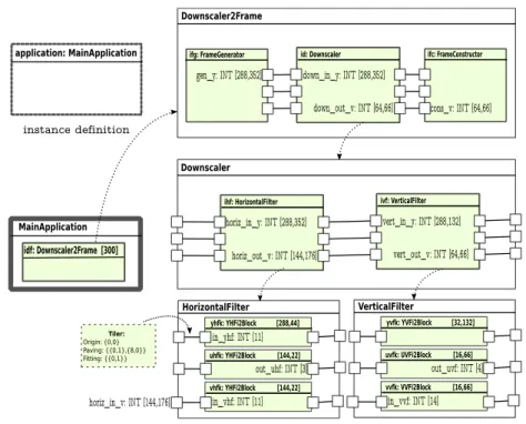
In order to create an application we use the framework of Gaspard2. This framework uses the Integrated Development Environment(IDE) Eclipse [5]. The Gaspard2 model of the downscaler application is illustrated in the figure 8. The model describes an instance of MainApplication that consists of 300 repetitive tasks Downscaler2Frame. This task is represented by two single tasks for the video reading and presentation (FrameGenerator and FrameConstructor) and an hierarchical task consisting of three levels: top level, a repetitive task re-ferred to as Downscaler; second level, a compound component represented by a directed acyclic graph where the nodes are repetitive tasks HorizontalFilter and VerticalFilter; and third level, elementary tasks HFilter and VFilter that are repeated within the repetitive tasks of second level.
Application Model Example The whole downscaler receives frames from
a 30fps CIF format 10-seconds video, denoted by the input 2D array (352,288), and produces a set of 300 transformed frames in QCIF format (176x144). The video pixels are encoded in 12-bit (a byte integer) YUV (4:2:0) color format. The FrameGenerator in each iteration(n of 300) of the Downscaler2Frame re-trieves one frame of 352x288 12-bit pixels. This task split the pixels into three parts: Y for the luminance component (the brightness) and U(Cb) and V(Cr) for the chrominance (color) components. The horizontal and vertical filters have 3 repetitive tasks, one for each color/brightness section. These tasks re-peat according to bytes processed at time. For example, the yhfk instance of YHFi2Block is a [288,44] repetitive task and has an input 11-bytes(8-bits in-teger) port. The tiler specified in this example allows to gather 11 luminance component from a 352x288 frame, the task repetition grants the whole scanning (considering the pixel interpolation) of the frame.
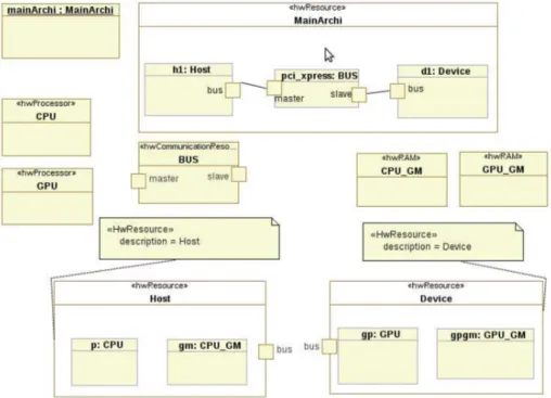
Architecture Model Example The proposed host and device architectures
do not explore the memory hierarchy. This simplify data allocations and com-munications for this Downscaler example. Thus, the architecture (figure 9)
con-application: MainApplication
MainApplication
idf: Downscaler2Frame [300]
instance definition
ifg: FrameGenerator id: Downscaler ifc: FrameConstructor
Downscaler2Frame
gen_y: INT [288,352] down_in_y: INT [288,352]
down_out_v: INT [64,66] cons_v: INT [64,66]
Downscaler ihf: HorizontalFilter horiz_in_v: INT [144,176] ivf: VerticalFilter vert_in_y: INT [288,132] vert_out_v: INT [64,66] yhfk: YHFi2Block [288,44] uhfk: YHFi2Block [144,22] in_vhf: INT [11] vhfk: YHFi2Block [144,22] HorizontalFilter Tiler: Origin: {0,0} Paving: {{0,1},{8,0}} Fitting: {{0,1}} horiz_out_v: INT [144,176] out_uhf: INT [3] horiz_in_y: INT [288,352] yvfk: YVFi2Block [32,132] uvfk: UVFi2Block [16,66] in_vvf: INT [14] vvfk: VVFi2Block [16,66] VerticalFilter out_uvf: INT [4] in_yhf: INT [11]
Figure 8: Downscaler Application Model
sists in host(CPU) and device(GPU) and their respective global memories. De-scriptively, the model consists of an architecture instance, two processor blocks stereotyped as hwProcessor, two memory blocks stereotypes as hwRAM and a BUS stereotyped as hwCommunicationResource. These blocks will constitute other elements in the architecture. Host and device are connected through PCI-Express bus that, eventually, provides information to model and to gener-ate code concerning data transfers. Again, as seen in the section 3.1.2, host and device are recognized by means of tagged values.
Allocation Model Example Subsequently, with application and
architec-ture models defined, we can make the allocation procedure. Allocation, as showed in the section 3.1.3, implies task and data allocation. The first one indi-cates who executes the task. This allocation is made using an UML abstraction connector (stereotyped as allocate) that creates a link between task defined in the application model and the processor defined in the architecture model. This link will allow to identify OpenCL kernels. Default behaviors are considered in allocation step. For instance, tasks, not explicitly allocated, are executed by host processor. The figure 10 illustrates three tasks (yhfk, uhfk and vhfk) allocated onto gp, an instance of GPU processor. Consequently, these tasks will be kernels in the Hybrid model. The application developer is the responsible to define which tasks are allocated on which compute devices. There is no ex-plicit rule, although repetitive tasks with intensive data processing are the best candidates.
Figure 9: Downscaler Architecture Model
yhfk: YHFi2Block [288,44] uhfk: YHFi2Block [144,22] vhfk: YHFi2Block [144,22]
HorizontalFilter
From application model From architecture model
gp: GPU
Device
Figure 10: Task Allocation
The figure 11 depicts a simple example to allocate flowPorts onto memory components. Usually, these allocations follow task allocations at architecture level. Otherwise, inconsistency will occur in data access. According to Hybrid metamodel, during the code generation, transformations inquiry interconnected ports allocated onto distinct processors. Case it happens (and it should), this represents data transfers between allocated memories. This situation is illus-trated in the figure 11, when the flowPort of the internal task yhfk is allocated onto gpgm, an instance of the GPU global memory, and another flowPort is allocated onto the gm, an instance of the CPU global memory.
Deployment Model Example In design time, it is not necessary to re-write
code details of the Downscaler example. Basic functions (IP) can be deployed over elementary components. These IPs are normally optimized functions (code
yhfk: YHFi2Block [288,44] uhfk: YHFi2Block [144,22] vhfk: YHFi2Block [144,22]
HorizontalFilter
From application model From architecture model
gpgm: GPU_GM Device gm: CPU_GM Host <<abstraction>> <<allocate>>
Figure 11: Data Allocation
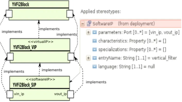
source or pre-compiled libraries) ready to use and available on design time. The figure 12 illustrates the deployment of virtualIP and softwareIP on the elementary component YVFi2Block. The deployment occurs at task and inter-face (data) levels. The data interinter-face is an important deployed aspect to define parameter order, for example. Currently, multiple softwareIP, IP entry names, can be deployed on only one elementary component. Therefore, the virtualIP al-lows to create a interface layer in order to choose one of the available softwareIP. This feature aims to link softwareIP from different target platforms, i.e. differ-ent programming languages (Gaspard2 can generate code for multi-platforms). Nevertheless, this particularity is not present in this example.
YVFi2Block
YVFi2Block_VIP <<virtualIP>>
YVFi2Block_SIP <<softwareIP>>
vin_ip vout_ip implements implementsimplements
implements implements
implements
Figure 12: Deployment Example
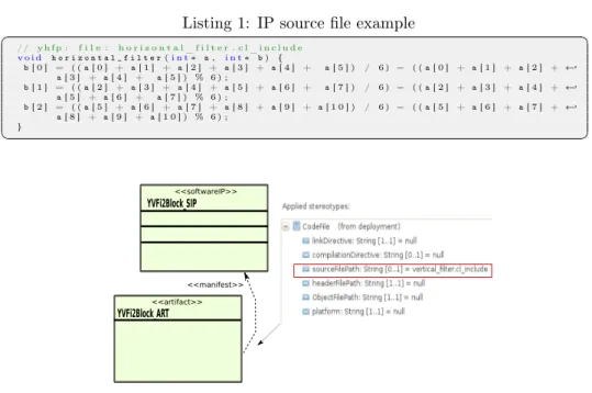
The figure 13 shows an artifact and software IP relationship. Artifacts are a "physical" pieces of information, such as files, models, or tables. Artifacts are said to be manifested from an element abstraction. In the context of a Deployment diagram, this could be, for example, a component. This relationship is represented with the ’manifest’ relationship. Among other definitions that can be set, we emphasize the source file path. The code listing 1 is just an IP example deployed on horizontal filter of the Downscaler.
Listing 1: IP source file example ✞ ☎ // y h f p : f i l e : h o r i z o n t a l _ f i l t e r . c l _ i n c l u d e v o i d h o r i z o n t a l _ f i l t e r(i n t∗ a , i n t∗ b ) { b[ 0 ] = ( ( a [ 0 ] + a [ 1 ] + a [ 2 ] + a [ 3 ] + a [ 4 ] + a[ 5 ] ) / 6 ) − ( ( a [ 0 ] + a [ 1 ] + a [ 2 ] + ←֓ a[ 3 ] + a [ 4 ] + a[ 5 ] ) % 6 ) ; b[ 1 ] = ( ( a [ 2 ] + a [ 3 ] + a [ 4 ] + a [ 5 ] + a [ 6 ] + a[ 7 ] ) / 6 ) − ( ( a [ 2 ] + a [ 3 ] + a [ 4 ] + ←֓ a[ 5 ] + a [ 6 ] + a[ 7 ] ) % 6 ) ; b[ 2 ] = ( ( a [ 5 ] + a [ 6 ] + a [ 7 ] + a [ 8 ] + a [ 9 ] + a [ 1 0 ] ) / 6 ) − ( ( a [ 5 ] + a [ 6 ] + a [ 7 ] + ←֓ a[ 8 ] + a [ 9 ] + a [ 1 0 ] ) % 6 ) ; } ✝ ✆ YVFi2Block_SIP <<softwareIP>> <<manifest>> YVFi2Block_ART <<artifact>>
Figure 13: Software IP Association
Transformations and Results Since we have the models defined in design
time, a single step triggers the transformations illustrated in figure 4. We choose the Downscaler model (UML file) in the IDE Eclipse, then we execute the OpenCL chain. This generates source files (.cpp, .cl) and a makefile. The listing 2, it is a resulting kernel code file. Here, we discuss some generation results. For space constraints, we did not show the whole generated code, but just some key parts of the generation. At the line 3, the attribute "const" repre-sents transformed port elements declared as "in" in the application model. The thread(WI) ID is inserted by template(line 9) and it is is automatically defined as global index in the thread grid. For this example, the rest of the code is split into 3 parts: tiler in, IP call and a tiler out. The tilers calculate the data pattern assigned to the indexed thread. The IP function processes this pattern and gives it back to another tiler (out) that writes in global memory.
The generated code was compiled with NVIDIA’s OpenCL compiler and executed in a desktop machine with a GTX285 card [13]. GTX285 provides 159GB/s bandwidth between its 240 cores and 1GB of GDDR3 RAM. This compares with 15-20GB/s achievable with the fastest conventional CPUs today. The result is a functional application as defined in its specifications.
Listing 2: Y-Component Horizontal Filter Kernel Source File ✞ ☎ _ _ k e r n e l v o i d k y h f( u i n t i N u m E l e m e n t s, 2 _ _ g l o b a l i n t∗ y h f _ o u t k _ k y h f, c o n s t _ _ g l o b a l i n t∗ y h f _ i n k _ k y h f 4 ) { 6 i n t i n _ y h f _ y h f p[ 1 1 ] ; i n t o u t _ y h f _ y h f p[ 3 ] ; 8 // g e t i n d e x i n t o g l o b a l d a t a a r r a y ( x , y , z ) x + s x ∗ y + ( s x ∗ s y ) ∗ z i n t i G I D = g e t _ g l o b a l _ i d ( 0 ) + g e t _ g l o b a l _ s i z e ( 0 ) ∗ g e t _ g l o b a l _ i d ( 1 ) + ←֓ g e t _ g l o b a l _ s i z e( 0 ) ∗ g e t _ g l o b a l _ s i z e ( 1 ) ∗ g e t _ g l o b a l _ i d ( 2 ) 10 // bound c h e c k i f ( i G I D < i N u m E l e m e n t s ) 12 { //−−−−−−−−−−−− T i l e r yhf_ink_kyhf : : in_yhf_yhfp −−−−−−−−−−−− 14 { u i n t t l I t e r[ 2 ] ; 16 u i n t t l[ 1 ] ; u i n t r e f[ 2 ] ; 18 u i n t i n d e x[ 2 ] ; t l I t e r[ 0 ] = i G I D %288; 20 t l I t e r[ 1 ] = a b s ( i G I D / 2 8 8 ) ; r e f[ 0 ] = 0+ 1∗ t l I t e r [ 0 ] + 0∗ t l I t e r [ 1 ] ; 22 r e f[ 1 ] = 0+ 0∗ t l I t e r [ 0 ] + 8∗ t l I t e r [ 1 ] ; f o r( t l [ 0 ] = 0 ; t l[ 0 ] < 1 1 ; t l[ 0 ] + + ) { 24 i n d e x[ 0 ] = ( r e f [ 0 ] + 0∗ t l [ 0 ] ) %288; i n d e x[ 1 ] = ( r e f [ 1 ] + 1∗ t l [ 0 ] ) %352; 26 i n _ y h f _ y h f p[ t l [ 0 ] ∗ 1 ] = y h f _ i n k _ k y h f [ i n d e x [ 0 ] ∗ 352 + i n d e x [ 1 ] ∗ 1 ] ; } 28 } h o r i z o n t a l _ f i l t e r( i n _ y h f _ y h f p , o u t _ y h f _ y h f p) ; // IP C a l l 30 //−−−−−−−−−−−− T i l e r out_yhf_yhfp : : yhf_outk_kyhf −−−−−−−−−−−− { 32 u i n t t l I t e r[ 2 ] ; u i n t t l[ 1 ] ; 34 u i n t r e f[ 2 ] ; u i n t i n d e x[ 2 ] ; 36 t l I t e r[ 0 ] = i G I D %288; t l I t e r[ 1 ] = a b s ( i G I D / 2 8 8 ) ; 38 r e f[ 0 ] = 0+ 1∗ t l I t e r [ 0 ] + 0∗ t l I t e r [ 1 ] ; r e f[ 1 ] = 0+ 0∗ t l I t e r [ 0 ] + 3∗ t l I t e r [ 1 ] ; 40 f o r( t l [ 0 ] = 0 ; t l[ 0 ] < 3 ; t l[ 0 ] + + ) { i n d e x[ 0 ] = ( r e f [ 0 ] + 0∗ t l [ 0 ] ) %288; 42 i n d e x[ 1 ] = ( r e f [ 1 ] + 1∗ t l [ 0 ] ) %132; y h f _ o u t k _ k y h f[ i n d e x [ 0 ] ∗ 132 + i n d e x [ 1 ] ∗ 1]= o u t _ y h f _ y h f p [ t l [ 0 ] ∗ 1 ] ; 44 } } 46 } e l s e r e t u r n; } ✝ ✆
5
Related Work
This work is part of Gaspard2 project, essentially an MDE approach to generate code for SoC platforms. Besides OpenCL, Gaspard2 aims to generate code to other platforms such as SystemC[6], OpenMP[21], Synchronous[7], VHDL[18] and Pthread[4] using respective transformation chains. These chains are de-signed according to intrinsic characteristics of each target platform.
Additionally, we can mention the Single Assignment C (SAC). SAC[20] is a strict purely functional programming language whose design is focused on the needs of numerical applications. Particular emphasis is laid on efficient sup-port for array processing. Efficiency concerns are essentially twofold. On the one hand, efficiency in program development is to be improved by the oppor-tunity to specify array operations on a high level of abstraction. On the other hand, efficiency in program execution, i.e. the runtime performance of programs both in time and memory consumption, is still to be achieved by sophisticated compilation schemes. Recently, it was released a branch[9] of this project that allows to generate code for CUDA. Similarities between CUDA and OpenCL were discuted in section 2.1.
In the field of OpenCL code generation, CAPS[2] proposes the CAPS HMPP toolkit. This toolkit is a set of compiler directives, tools and software runtime that supports multi-core and many-core processors parallel programming in C and Fortran. This approach is similar to a widely available standard, OpenMP, but designed to handle hardware accelerators.
6
Conclusions and Further Work
In this paper, we propose an MDE approach to generate OpenCL code. From an abstract model defined using UML/MARTE, we generate a compilable OpenCL code and then, a functional executable application. As MDE approach, this work intends to provide a tool for project reuse and fast development for not necessarily experts. This approach is an effective operational code generator for the newly released OpenCL standard. Further, although the case study is mono-device(one GPU) example, this approach provides resources to model applications running on multi-devices (homogeneously configured). Moreover, this work provides two main contributions for modeling with UML profile to MARTE. On the one hand, an approach to model distributed memory simple aspects, i.e. communication and memory allocations. On the other hand, an approach for modeling the platform and execution models of OpenCL.
The Hybrid metamodel proposed in this paper can be used by other target languages that conform the same memory, platform and execution models, such as CUDA language. Based on other created model-to-text templates, future works will exploit the multi-language aspect. Additionally, intelligent trans-formations can determine optimization levels in data communication and data access. Several studies show that these optimizations increase remarkably the application performance.
References
[1] A. Demeure, A. Lafage, E. Boutillon, D. Rozzonelli, J-C. Dufourd, J-L. Marro. Array-OL: Proposition d’un Formalisme Tableau pour le Traitement de Signal Multi-Dimensionnel. In Gretsi, Juan-Les-Pins, France, September 1995.
[2] CAPS Enterprise. HMPP Workbench, 2010.
[3] G. Cote, B. Erol, M. Gallant, and F. Kossentini. H.263+: video coding at low bit rates. Circuits and Systems for Video Technology, IEEE Transac-tions on, 8(7):849–866, 1998.
[4] DaRT Team LIFL/INRIA, Lille, France. Graphical array specification for parallel and distributed computing (Gaspard2), 2010.
[5] Eclipse. Eclipse Modeling Framework, 2010.
[6] Éric Piel, Samy Meftali, Jean luc Dekeyser, Rabie Ben Atitallah, Smaïl Niar, Anne Etien, and Pierre Boulet. Gaspard2: from marte to systemc simulation. Proceedings of the DATE’08 workshop on Modeling and Anal-ysis of Real-Time and Embedded Systems with the MARTE UML profile, 2008.
[7] Abdoulaye Gamatié, Eric Rutten, Huafeng Yu, Pierre Boulet, and Jean-Luc Dekeyser. Synchronous modeling and analysis of data intensive appli-cations. EURASIP Journal on Embedded Systems, 2008.
[8] Calin Glitia, Pierre Boulet, Eric Lenormand, and Michel Barreteau. Repet-itive Model Refactoring for Design Space Exploration of Intensive Signal Processing Applications. Technical report, 2009.
[9] Jing Guo, Jeyarajan Thiyagalingam, and Sven-Bodo Scholz. Towards Com-piling SAC to CUDA. In 10th Symposium on Trends in Functional Pro-gramming - TFP, 2009.
[10] Khronos OpenCL Working Group. The OpenCL Specification, version 1.0.29, 8 December 2008.
[11] Yu K. Kwok and Ishfaq Ahmad. Static scheduling algorithms for allocating directed task graphs to multiprocessors. ACM Comput. Surv., 31(4):406– 471, 1999.
[12] D. Lugato, J-M Bruel, and I. Ober. Model-Driven Engineering for High Performance Computing Applications, Modeling Simulation and Optimiza-tion - Focus on ApplicaOptimiza-tions. Shkelzen Cakaj (Ed.), 2010.
[13] NVidia. NVidia’s Developer Zone, 2010.
[14] Obeo. Acceleo - Model to Text transformation, 2010. [15] OMG. M2M/Operational QVT Language, 2007.
[16] OMG. Modeling and Analysis of Real-time and Embedded systems
[17] Imran Rafiq Quadri. MARTE based model driven design methodology for targeting dynamically reconfigurable FPGA based SoCs. PhD thesis, 2010. [18] Imran Rafiq Quadri, Samy Meftali, and Jean-Luc Dekeyser. Marte based modeling approach for partial dynamic reconfigurable fpgas. Sixth IEEE Workshop on Embedded Systems for Real-time Multimedia (ESTIMedia 2008), 2008.
[19] Michael J. Quinn. Parallel Programming in C with MPI and OpenMP. McGraw-Hill Education Group, 2003.
[20] Sven-Bodo Scholz. Single assignment c – efficient support for high-level array operations in a functional setting. In Journal of Functional Program-ming 13(6), pp.1005-1059, 2003.
[21] Julien Taillard, Frédéric Guyomarc’h, and Jean-Luc Dekeyser. Openmp code generation based on an model driven engineering approach. High Performance Computing & Simulation Conference (HPCS), 2008.
Contents
1 Introduction 3
2 Background Review 4
2.1 OpenCL Programming Model . . . 4
2.2 Model-Driven Engineering . . . 5
2.2.1 MARTE Profile . . . 6
3 Code Generation Approach 8 3.1 Design Time Models . . . 9
3.1.1 Application . . . 9 3.1.2 Architecture . . . 9 3.1.3 Allocation . . . 9 3.1.4 Deployment . . . 10 3.2 Transformations . . . 10 3.2.1 Model to Model . . . 11 3.2.2 Model to Text . . . 15 4 Case Study 17 4.1 Downscaler . . . 17
4.1.1 Gaspard2 Model for Downscaler . . . 17
5 Related Work 23
Centre de recherche INRIA Bordeaux – Sud Ouest : Domaine Universitaire - 351, cours de la Libération - 33405 Talence Cedex Centre de recherche INRIA Grenoble – Rhône-Alpes : 655, avenue de l’Europe - 38334 Montbonnot Saint-Ismier
Centre de recherche INRIA Nancy – Grand Est : LORIA, Technopôle de Nancy-Brabois - Campus scientifique 615, rue du Jardin Botanique - BP 101 - 54602 Villers-lès-Nancy Cedex
Centre de recherche INRIA Paris – Rocquencourt : Domaine de Voluceau - Rocquencourt - BP 105 - 78153 Le Chesnay Cedex Centre de recherche INRIA Rennes – Bretagne Atlantique : IRISA, Campus universitaire de Beaulieu - 35042 Rennes Cedex Centre de recherche INRIA Saclay – Île-de-France : Parc Orsay Université - ZAC des Vignes : 4, rue Jacques Monod - 91893 Orsay Cedex
Centre de recherche INRIA Sophia Antipolis – Méditerranée : 2004, route des Lucioles - BP 93 - 06902 Sophia Antipolis Cedex
Éditeur
INRIA - Domaine de Voluceau - Rocquencourt, BP 105 - 78153 Le Chesnay Cedex (France) http://www.inria.fr