HAL Id: pastel-00001360
https://pastel.archives-ouvertes.fr/pastel-00001360
Submitted on 22 Aug 2005HAL is a multi-disciplinary open access
archive for the deposit and dissemination of
sci-L’archive ouverte pluridisciplinaire HAL, est destinée au dépôt et à la diffusion de documents
oxide scales mechanical behavior in hot rolling
Benjamin Picque
To cite this version:
Benjamin Picque. Experimental study and numerical simulation of iron oxide scales mechanical be-havior in hot rolling. Engineering Sciences [physics]. École Nationale Supérieure des Mines de Paris, 2004. English. �pastel-00001360�
DE PARIS
Ecole Doctorale 364 : Sciences Fondamentales et Appliquées
N° attribué par la bibliothèque
|__|__|__|__|__|__|__|__|__|__|
T H E S E
pour obtenir le grade de
Docteur de l’Ecole des Mines de Paris
Spécialité «Mécanique Numérique»
présentée et soutenue publiquement par
M. Benjamin Picqué
le 7 Septembre 2004
E
XPERIMENTAL
S
TUDY AND
N
UMERICAL
S
IMULATION OF
I
RON
O
XIDE
S
CALES
M
ECHANICAL
B
EHAVIOR IN
H
OT
R
OLLING
(Etude expérimentale et simulation numérique
du comportement mécanique des calamines lors du laminage à chaud)
Directeurs de thèse :Pierre MONTMITONNET, Pierre-Olivier BOUCHARD
Jury :
Pr.
Gérard
Moulin
Président
Pr. John H. Beynon
Rapporteur
Pr.
Laurent
Dubar
Rapporteur
M.
Vincenzo
Lanteri
Examinateur
Je tiens tout d’abord à remercier Messieurs Jacques Lévy et Benoit Legait, directeurs successifs de l’école des Mines de Paris, pour m’avoir permis d’effectuer ma thèse au sein de l’un de ses laboratoires. Ma gratitude va également au directeur du CEMEF, Monsieur Jean-Loup Chenot.
Merci aux membres du jury de cette thèse : le Pr. J.H Beynon de l’Université de Sheffield, le Pr. L.Dubar de l’université de Valenciennes, le Pr. Moulin de l’Université technologique de Compiègne. Un merci tout particulier au Pr. Beynon pour avoir fait le déplacement et m’avoir permis de suer sang et eau sur ce manuscrit en anglais. Merci également au Pr. Moulin pour les échanges très intéressants que nous avons eus au cours de cette thèse. Mes remerciements vont ensuite tout naturellement à mes directeurs de thèse : Pierre Montmitonnet et Pierre-Olivier Bouchard. J’ai eu énormément de chance de vous avoir tous deux pour diriger ma thèse. Merci pour vos conseils, votre encadrement continuel me laissant cependant une grande autonomie. Merci à vous deux pour la confiance que vous m’avez accordée notamment lors de la rédaction « in english ». Ca ne m’a pas été facile, vous m’avez énormément aidé dans cette étape, mais je reconnais que pour moi l’effort en valait vraiment la peine. Merci également pour tous les moments amicaux passés ensemble.
Je remercie Vincent Lanteri et Michel Picard pour avoir encadré cette thèse avec bonne humeur en me laissant une grande autonomie. Merci pour avoir également facilité des collaborations avec d’autres universités.
Je remercie ma petite Kikou (Monique Repoux) pour des tonnes de raisons. D’abord pour ton savoir : je ne compte plus le nombre de fois où tu m’as solutionné un problème (eh oui, on a toujours besoin d’un plus petit que soi). Merci pour tous les fous rires, les moments de complicité, pour ton écoute quel qu’en soit le sujet et pour ta gentillesse. Merci également pour tes magnifiques phrases du jour et proverbes « moniquiens ». Au fait, je me demande dans quel état est ton bureau depuis que je suis parti ? Le mien est hélas toujours aussi bordélique !
Merci aux IENNIENS, François, PO, Hic, Katia, Yvan Chastel, pour tous les super-moments passés ensemble dans ce groupe très soudé. Je garderai également en mémoire le championnat de foot remporté haut la main par notre équipe, ainsi que le magnifique short de François ;-)
Merci à Didier Zint, technicien de l’Irsid, pour sa disponibilité et son aide lors des essais de flexion 4 points. J’en profite pour remercier le reste de l’équipe pour son accueil.
Merci à Audrey Paccini et Serge Mouret pour les bons stages qu’ils ont réalisés et leur participation aux résultats de cette thèse.
Merci à toutes les personnes qui m’ont rendu toutes ces années agréables : Isa, Benoît, Sev, Manu Levrat (le roi des phoques), MYP, Robert Combarieu, l’équipe de l’atelier, Suzanne Jacomet, Patoche.
Enfin, je voudrais remercier pour terminer les personnes les plus chères à mon cœur, ma famille et mes amis. Je pense que vous savez tous ce que vous représentez pour moi. Je ne m’étendrai donc pas, ce serait trop long et je préfère le faire de vive voix. En quelques mots : Manue (la plus adorable, talentueuse et sexy des conseillères administratives), Jul (maille anglich titcheur, merci pour la relecture d’une partie de ce manuscrit : et dire que t’as raté la soutenance !), Tof (the best of crazy Fenwick drivers), Aurel (ma thésarde préférée du CEMEF). Merci pour votre amitié sans faille. Enfin, comme dirait le grand Djumbowitch « Si vous étiez vraiment des amis, vous viendriez habiter à Pamiers ! » :-(
Mes parents : Je ne vous remercierai jamais assez de m’avoir toujours poussé, soutenu et permis d’en arriver là. Merci aussi d’avoir organisé « champagnifiquement » ma soirée de thèse qui concluait en beauté une inoubliable journée.
Mam, ta cocotte restera comme pièce de musée !
Merci à ma grand-mère, Simonne, pour tout, pour son aide permanente, pour le fait d’accompagner ma vie tout simplement, sans jamais être trop loin de moi.
Merci à ma sœur d’avoir toujours été là quand j’en avais besoin. Qu’elle sache que notre complicité est extrêmement importante pour moi.
Merci à ma grand-mère Léonie, pour ses encouragements et pour être venue assister à ma soutenance.
Anne, merci d’avoir toujours su que ça se passerait bien, merci pour ta confiance et ton soutien.
Merci également à mon Beaup’ Didier (même s’il ne connaît pas son do), ma marâtre préférée Nath, mon petit Xav, Aurélie Paulette, Guillaume alias Sir William (faudrait quand même qu’on commence à répéter notre prochain concert) et Manue pour votre soutien et vos encouragements.
Enfin, merci à mon p’tit bout, Salia. Merci de m’avoir supporté surtout lors des difficiles six derniers mois, de m’avoir toujours encouragé et motivé ; merci d’être toujours présente. Tu es mon petit soleil. Je t’aime.
A mon grand père …
A mon petit frère …
INTRODUCTION
CHAPTER I. HOT ROLLING PROCESS
I. INTRODUCTION ... 9
II. HOT ROLLING PROCESS... 9
III. FINISHING MILL ... 13
IV. A STAND ... 14
V. THERMO-MECHANICAL DESCRIPTION ... 15
V.1.GENERALITIES... 15
V.2.FRICTION... 17
V.2.1. Friction and engagement conditions... 17
V.2.2. Friction coefficient ... 19
V.3.THERMAL CYCLE IN ROLLING... 21
V.4.HEAT TRANSFER IN A FM STAND AND THEIR CONSEQUENCES... 22
V.4.1. Heat exchanges assessment... 22
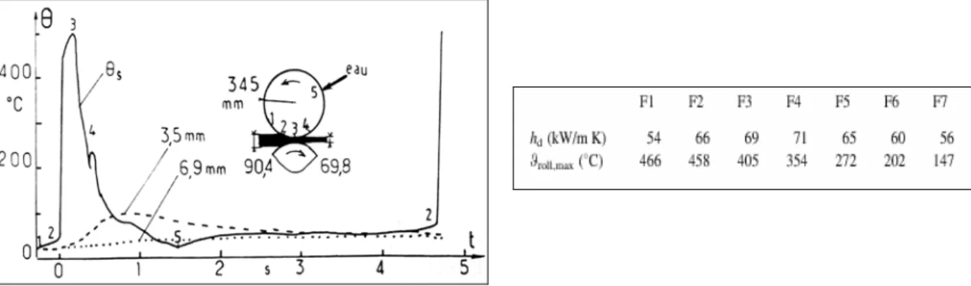
V.4.2. The interfacial heat transfer coefficient (IHTC) ... 24
V.4.3. Work-rolls degradation ... 27
VI. ORIGIN OF SECONDARY SCALE DEFECTS... 30
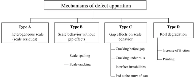
VI.1.DEFECTS... 30
VI.2.INITIATION MECHANISMS OF THE ROLLED-IN SCALE DEFECT... 33
VI.2.1. Scale residues in exit of FSB descaling (Type A) ... 33
VI.2.2. Stresses in scale without gap effects (type B) ... 33
VI.2.3. Defects related to rolling stresses (Type C)... 35
VI.2.4. Defects generated by roll degradation (Type D) ... 36
VI.2.5. Finally ... 37
VII. EXAMPLES OF ROLLING ... 38
VII.1.INDUSTRIAL ROLLING MILL... 38
VII.2.PILOT ROLLING MILL... 40
VIII. CONCLUSION ... 45
I. INTRODUCTION ... 53
II. PHYSICAL PROPERTIES... 53
II.1.OXIDATION GROWTH... 53
II.1.1. Bibliography ... 53
II.1.2. Oxidation kinetics – Scale thickness ... 55
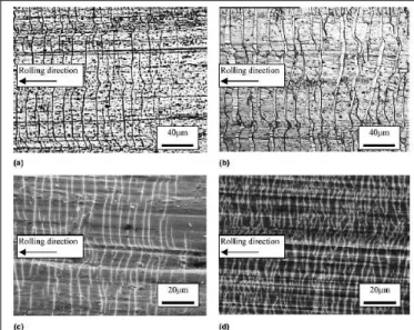
II.2.OXIDE SCALE MORPHOLOGY IN THE FINISHING MILL... 60
II.2.1. Adapted thermal cycle and oxidation atmosphere... 60
II.2.2. Preparation and microscopic observations of the oxide layer ... 61
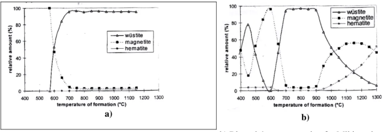
II.2.3. Composition using x-rays diffraction analysis (XRD) ... 63
II.2.4. Other analyses ... 65
II.3.THE TEMPERATURE: A KEYPOINT FOR SURFACE QUALITY... 66
II.3.1. The first parameter: the slab temperature ... 66
II.3.2. Thickness of the oxide layer after the secondary descaling... 67
II.3.3. Effects on the acceptable maximum temperatures... 68
II.3.4. The true limit can be on the F2 stand ... 69
III. OXIDE SCALE MECHANICAL PROPERTIES ... 71
III.1.THIN SCALE COATING... 71
III.2.MECHANICAL PROPERTIES... 72
III.3.OXIDE SCALE BEHAVIOR... 74
III.4.STRESSES EVALUATION AND DAMAGE CRITERIA... 76
III.4.1. Fracture mechanics theory ... 77
III.4.2. Interstand... 80
III.4.3. Roll gap entry ... 88
III.4.4. Under the rolls... 89
IV. CONCLUSION ... 91
I. INTRODUCTION ... 99
II. THE EQUATIONS OF MECHANICS ... 99
II.1.MECHANICAL FORMULATION... 99
II.2.CONSTITUTIVE MODELLING... 100
II.3.BOUNDARY CONDITIONS... 102
II.3.1. In the normal direction of an interface between two bodies... 102
II.3.2. In the tangential direction... 103
II.3.3. Standard implementation ... 103
II.4.STRONG FORMULATION OF THE MECHANICAL PROBLEM... 104
III. VARIATIONAL FORMULATION ... 105
III.1.CONTINUOUS FORM OF THE WEAK FORMULATION... 105
III.2.FINITE ELEMENT SPATIAL DISCRETIZATION... 105
III.3.TEMPORAL DISCRETIZATION... 107
IV. GENERALISATION OF CONTACT MANAGEMENT IN FORGE2® ... 108
IV.1.OUR OBJECTIVE... 108
IV.2.ACZM APPROACH... 109
IV.3.EXTENSION OF CONTACT MANAGEMENT IN FORGE2® ... 111
IV.3.1. Tangential direction... 111
IV.3.2. Normal direction... 113
IV.3.3. Comparison between our extensions and the CZM model ... 114
IV.3.4. Coupling... 114
IV.4.EXAMPLES... 115
IV.4.1. Interfacial sliding... 115
IV.4.2. Decohesion... 116
IV.4.3. Sliding and decohesion coupling ... 117
V. TRANSVERSE CRACKS ... 118
V.1.PRE-EXISTING CRACKS... 118
V.2.A MORE REALISTIC MODEL... 120
VI. CONCLUSIONS ... 121
I. INTRODUCTION ... 128
II. BIBLIOGRAPHY ... 129
III. THE FOUR POINT HOT BENDING TEST OF IRSID (4-PHBT) ... 136
III.1.TEST PREPARATION... 137
III.2.THE HEATING SYSTEM... 138
III.3.WET ATMOSPHERE GENERATOR... 138
III.4.SPECIMENS PREPARATION... 138
III.5.EXPERIMENTAL PROCEDURE... 139
III.6.THE ACOUSTIC EMISSION INSTRUMENTATION... 141
IV. 4-PHBT RESULTS ... 142
IV.1.GENERAL BEHAVIOR OF NON-OXIDIZED SPECIMENS... 142
IV.2.GENERAL BEHAVIOR OF OXIDIZED SPECIMENS... 145
IV.2.1. Damage ... 145
IV.2.2. A granular structure ... 147
IV.2.3. Experimental load-deflection curves ... 148
IV.3.INFLUENCE OF THE 4-PHBT PARAMETERS ON SCALE DAMAGE... 149
IV.3.1. Temperature influence ... 149
IV.3.2. Strain influence ... 150
IV.3.3. Steel grade influence... 150
IV.3.4. Scale thickness influence ... 151
IV.3.5. Strain rate influence... 152
IV.3.6. Summary of parameters influence ... 153
IV.3.7. Crack density depending on parameters ... 154
V. THE SIGNIFICANT CONTRIBUTION OF THE AE... 155
V.1.FIRST WORKS... 155
V.2.CRACKS INITIATION... 157
V.3.IDENTIFICATION OF EVENTS... 157
V.4.CONCLUSION... 161
VI. DETERMINATION OF BEHAVIOR LAWS FOR STEEL AND SCALE ... 161
VI.1.THE INVERSE ANALYSIS [APPENDIX4,PIC1]... 161
VI.2.STEEL PARAMETERS IDENTIFICATION... 162
VI.2.1. Sensitivity study... 162
VI.2.2. Identification of steel mechanical parameters by inverse analysis method... 163
VI.3.OXIDE SCALE CONSTITUTIVE EQUATIONS... 167
VI.3.1. Young's modulus identification ... 167
VI.3.2. Viscoplastic behavior (800°C-900°C) ... 168
VI.3.3. Extrapolation to 600°C / 700°C ... 172
IX. REFERENCES... 179
CHAPTER V. EXTENSION TO OTHER STRAIN AND
STRESS STATES: TENSION AND COMPRESSION
I. HOT TENSILE TEST (HTT)... 184I.1. A FOCUSED BIBLIOGRAPHIC STUDY... 184
I.2. OUR EXPERIMENTAL DEVICE... 188
I.3. USEFUL DATA... 189
I.4. EXPERIMENTAL RESULTS AND PARAMETERS INFLUENCE... 189
I.4.1. Influence of temperature ... 189
I.4.2. Influence of strain... 190
I.4.3. Influence of strain rate ... 193
I.4.4. Influence of scale thickness ... 193
I.4.5. LC steel and Ex-LC steel ... 195
I.5. LOAD-ELONGATION CURVES... 195
I.6. NUMERICAL SIMULATION OF TENSILE TEST... 196
I.7. CONCLUSION ON HOT TENSILE TEST... 199
II. PLANE STRAIN COMPRESSION TEST (PSCT)... 200
II.1. A HOT ROLLING MODEL... 200
II.2. THE EXPERIMENTAL DEVICE... 203
II.3. MECHANICAL BEHAVIOR OF THE OXIDE SCALE DURING PSCT... 203
II.4. SIMPLIFIED NUMERICAL SIMULATION OF PSCT ... 205
II.4.1. A simplified model ... 205
II.4.2. Parameters influence on extrusion... 206
II.5. EXTRUSION STUDY USING PSCT ... 209
II.6. CONCLUSION ON PSCT ... 212
III. CONCLUSION... 213
I. INTRODUCTION ... 217
II. A FOCUSED BIBLIOGRAPHIC STUDY ... 217
III. REFINING BOXES... 221
IV. SIMULATION OF HOT STRIP ROLLING IN A FM STAND ... 223
IV.1.THE F2 STAND AS A REFERENCE... 223
IV.2.LOCATION ON THE STRIP... 224
IV.3.INFLUENCE OF THE TEMPERATURE... 226
IV.3.1. Scale temperature... 226
IV.3.2. Work-rolls temperature ... 227
IV.4. INFLUENCE OF REDUCTION... 228
IV.5. INFLUENCE OF SCALE THICKNESS... 229
IV.6. INFLUENCE OF ROLLING SPEED... 229
IV.7. INFLUENCE OF FRICTION... 230
V. INITIAL DEFECTS... 230
V.1.OVER-OXIDATION... 230
V.2.COLD OXIDE RESIDUE... 231
V.3.BLISTER DEFECT... 231
VI. CONCLUSIONS ... 232
VII. REFERENCES ... 233
GENERAL CONCLUSION AND PERSPECTIVES
INTRODUCTION
CHAPITRE I. LE LAMINAGE A CHAUD
I. INTRODUCTION ... 9
II. LE LAMINAGE A CHAUD ... 9
III. LE FINISSEUR... 13
IV. UNE CAGE ... 14
V. DESCRIPTION THERMO-MECANIQUE ... 15
V.1.GÉNÉRALITÉS... 15
V.2.FROTTEMENT... 17
V.2.1. Frottement et conditions d'engagement ... 17
V.2.2. Coefficient de frottement ... 19
V.3.CYCLE THERMIQUE EN LAMINAGE... 21
V.4.TRANSFERT THERMIQUE DANS UNE CAGE DE FINISSEUR ET LEURS CONSEQUENCES... 22
V.4.1. Bilan des échanges thermiques ... 22
V.4.2. Le coefficient de transfert thermique interfacial... 24
V.4.3. Dégradation des cylindres ... 27
VI. ORIGINE DES DEFAUTS DE CALAMINE SECONDAIRE... 30
VI.1.LES DEFAUTS... 30
VI.2.MECANISMES D'INITIATION DES DEFAUTS D'INCRUSTATION... 33
VI.2.1. Résidus de calamine en sortie de décalaminage FSB (Type A)... 33
VI.2.2. Contraintes dans la calamine sans effets d'emprise (type B) ... 33
VI.2.3. Défauts liés aux contraintes de laminage (Type C) ... 35
VI.2.4. Défauts liés à la dégradation des cylindres (Type D) ... 36
VI.2.5. Bilan... 37
VII. EXEMPLES DE LAMINAGE ... 38
VII.1.LAMINOIR INDUSTRIEL... 38
VII.2.LAMINOIR PILOTE... 40
VIII. CONCLUSION ... 45
I. INTRODUCTION ... 53
II. PROPRIETES PHYSIQUES ... 53
II.1.CROISSANCE DE L'OXYDATION... 53
II.1.1. Bibliographie ... 53
II.1.2. Cinétiques d'oxydation– Epaisseur de calamine ... 55
II.2.MORPHOLOGIE DE LA CALAMINE DANS LE FINISSEUR... 60
II.2.1. Cycle thermique adapté et atmosphère d'oxydation ... 60
II.2.2. Préparation et observations microscopiques de la calamine ... 61
II.2.3. Composition en analyse de diffraction de rayons X (DRX) ... 63
II.2.4. Autres analyses ... 65
II.3.LA TEMPERATURE:UN PARAMETRE CLE POUR LA QUALITE DE SURFACE... 66
II.3.1. Le premier paramètre: la température de brame ... 66
II.3.2. Epaisseur de calamine après décalaminage secondaire ... 67
II.3.3. Les effets sur les températures maximales acceptables ... 68
II.3.4. La vraie limite peut être sur la cage F2... 69
III. PROPRIETES MECANIQUE DE LA CALAMINE ... 71
III.1.COUCHE MINCE DE CALAMINE... 71
III.2.PROPRIETES MECANIQUES... 72
III.3.COMPORTEMENT DE LA CALAMINE... 74
III.4.EVALUATION DES CONTRAINTES ET CRITERES D'ENDOMMAGEMENT... 76
III.4.1. Théorie de la mécanique de la rupture... 77
III.4.2. Intercage ... 80
III.4.3. Entrée d'emprise ... 88
III.4.4. Dans l'emprise ... 89
IV. CONCLUSION ... 91
I. INTRODUCTION ... 99
II. LES EQUATIONS DE LA MECANIQUE... 99
II.1.FORMULATION MECANIQUE... 99
II.2.MODELISATION CONSTITUTIVE... 100
II.3.CONDITIONS LIMITES... 102
II.3.1. Dans la direction normale à l'interface entre deux corps ... 102
II.3.2. Dans la direction tangentielle... 103
II.3.3. Implémentation standard ... 103
II.4.FORMULATION FORTE DU PROBLEME MECANIQUE... 104
III. FORMULATION VARIATIONNELLE ... 105
III.1.FORME CONTINUE DE LA FORMULATION FAIBLE... 105
III.2.DISCRETISATION SPATIALE ELEMENTS FINIS... 105
III.3.DISCRETISATION TEMPORELLE... 107
IV. GENERALISATION DE LA GESTION DU CONTACT DANS FORGE2® ... 108
IV.1.NOS OBJECTIFS... 108
IV.2.L'APPROCHE CZM ... 109
IV.3.EXTENSION DE LA GESTION DU CONTACT DANS FORGE2®... 111
IV.3.1. Direction tangentielle ... 111
IV.3.2. Direction normale... 113
IV.3.3. Comparaison entre nos extensions et le modèle CZM... 114
IV.3.4. Couplage ... 114
IV.4.EXEMPLES... 115
IV.4.1. Glissement interfacial ... 115
IV.4.2. Décohésion... 116
IV.4.3. Couplage entre glissement et décohésion ... 117
V. FISSURES TRANSVERSES... 118
V.1.FISSURES PRE-EXISTANTES... 118
V.2.UN MODELE PLUS REALISTE... 120
VI. CONCLUSIONS ... 121
I. INTRODUCTION ... 128
II. BIBLIOGRAPHIE ... 129
III. L'ESSAI DE FLEXION 4 POINTS DE L'IRSID... 136
III.1.PREPARATION DU TEST... 137
III.2.LE SYSTEME DE CHAUFFAGE... 138
III.3.LE GENERATEUR D'ATMOSPHERE HUMIDE... 138
III.4. PREPARATION DES EPROUVETTES... 138
III.5.PROCEDURE EXPERIMENTALE... 139
III.6.INSTRUMENTATION DE L'EMISSION ACOUSTIQUE... 141
IV. RESULTATS DES ESSAIS DE FLEXION 4 POINTS (F4P) ... 142
IV.1.COMPORTEMENT GENERAL DES EPROUVETTES NON-OXYDEES... 142
IV.2.COMPORTEMENT GENERAL DES EPROUVETTES OXYDEES... 145
IV.2.1. Endommagement... 145
IV.2.2. Une structure granulaire ... 147
IV.2.3. Courbes Expérimentales Force-Flèche ... 148
IV.3.INFLUENCE DES PARAMETRES DE F4P SUR L'ENDOMMAGEMENT DE LA CALAMINE.... 149
IV.3.1. Influence de la température ... 149
IV.3.2. Influence de la déformation ... 150
IV.3.3. Influence de la nuance d'acier ... 150
IV.3.4. Influence de l'épaisseur de la calamine ... 151
IV.3.5. Influence de la vitesse de déformation... 152
IV.3.6. Résumé sur l'influence des paramètres... 153
IV.3.7. Densité de fissures en fonction des paramètres... 154
V. L'IMPORTANTE CONTRIBUTION DE L'EMISSION ACOUSTIQUE... 155
V.1.PREMIERS TRAVAUX... 155
V.2.INITIATION DES FISSURES... 157
V.3.IDENTIFICATION DES EVENEMENTS... 157
V.4.CONCLUSION... 161
VI. DETERMINATION DES LOIS DE COMPORTEMENT POUR L'ACIER ET LA CALAMINE... 161
VI.1.L'ANALYSE INVERSE [ANNEXE4, PIC1]... 161
VI.2.IDENTIFICATION DES PARAMETRES DE L'ACIER... 162
VI.2.1. Etude de sensibilité ... 162
VI.2.2. Identification des paramètres mécaniques de l'acier par analyse inverse ... 163
VI.3.EQUATIONS CONSTITUTIVES DE LA CALAMINE... 167
VI.3.1. Identification du module d'Young ... 167
VI.3.2. Comportement Viscoplastique (800°C-900°C)... 168
IX. REFERENCES... 179
CHAPITRE V. EXTENSION AUX AUTRES ETATS DE
CONTRAINTE ET DEFORMATION : TRACTION ET
COMPRESSION
I. L'ESSAI DE TRACTION... 184I.1. UNE ETUDE BIBLIOGRAPHIQUE ORIENTEE... 184
I.2. L'INSTALLATION EXPERIMENTALE... 188
I.3. DONNEES UTILES... 189
I.4. RESULTATS EXPERIMENTAUX ET INFLUENCE DES PARAMETRES... 189
I.4.1. Influence de la température... 189
I.4.2. Influence de la déformation... 190
I.4.3. Influence de la vitesse de déformation ... 193
I.4.4. Influence de l'épaisseur de calamine ... 193
I.4.5. Aciers doux et extra-doux... 195
I.5. COURBES FORCE-ELONGATION... 195
I.6. SIMULATION NUMERIQUE DE L'ESSAI DE TRACTION... 196
I.7. CONCLUSION SUR L'ESSAI DE TRACTION... 199
II. L'ESSAI DE BIPOINCONNEMENT... 200
II.1. UN MODELE DE LAMINAGE... 200
II.2. L'INSTALLATION EXPERIMENTALE... 203
II.3. COMPORTEMENT MECANIQUE DE LA CALAMINE EN BIPOINCONNEMENT... 203
II.4. SIMULATION NUMERIQUE SIMPLIFIEE DU BIPOINCONNEMENT... 205
II.4.1. Un modèle simplifié... 205
II.4.2. Influence des paramètres sur l'extrusion ... 206
II.5. ETUDE DE L'EXTRUSION EN BIPOINCONNEMENT... 209
II.6. CONCLUSION SUR LE BIPONCONNEMENT... 212
III. CONCLUSION... 213
I. INTRODUCTION ... 217
II. UNE ETUDE BIBLIOGRAPHIQUE ORIENTEE... 217
III. BOITES DE RAFFINEMENT ... 221
IV. SIMULATION DU LAMINAGE A CHAUD D'UNE BANDE DANS UNE CAGE DE FINISSEUR ... 223
IV.1.LA CAGE F2 COMME REFERENCE... 223
IV.2.POSITION SUR LA BANDE... 224
IV.3.INFLUENCE DE LA TEMPERATURE... 226
IV.3.1. Température de la bande... 226
IV.3.2. Température des cylindres ... 227
IV.4.INFLUENCE DE LA REDUCTION... 228
IV.5.INFLUENCE DE L'EPAISSEUR DE CALAMINE... 229
IV.6.INFLUENCE DE LA VITESSE DE LAMINAGE... 229
IV.7.INFLUENCE DU FROTTEMENT... 230
V. DEFAUTS INITIAUX ... 230
V.1.SUR-OXYDATION... 230
V.2.RESIDU FROID D'OXYDE ... 231
V.3.BOURSOUFLURE... 231
VI. CONCLUSIONS ... 232
VII. REFERENCES ... 233
CONCLUSION GENERALE ET PERSPECTIVES
ANNEXES
Introduction
Introduction
INTRODUCTION
Context and industrial stakes
Hot rolling of steels represents one of the most critical steps to achieve finished products
having a high surface quality. The increasing productivity added to the rising customer requirements result in more and more severe scheduling rules for the HSM. Strip surface aspect is very important issue in terms of HSM operation costs and productivity limitation.
The present research was proposed by the ARCELOR group. ARCELOR is a merger of
Arbed, Aceralia, and Usinor, and was created by the common will of these three European
groups to mobilize their technical, industrial, and commercial skills to create a global leader aiming to be a major player in the steel industry. This group is developing its activities in four core businesses: it is the world's biggest producer of Flat Carbon Steel and Long Carbon Steel, among the leaders in Stainless Steel production, and among the largest firms in Europe for Distribution, Transformation and Trading.
In 2004, non-quality of coils represents 5.7% of the Dunkerque hot strip mill added costs. This cost is shared among the end of line inspectors, the maintenance of automatic
inspection system and the cost due to premature roll change. Nevertheless, the direct costs
of rolled-in scale defect are presently much lower than a few years ago. Indeed, apart from progress realized on new work-rolls grades, the rolling operators have established tight
programming rules, which dramatically decrease and nearly eliminate the rolled-in scale occurrence (internal customer claim ratio is currently below 0.1 %).
Nevertheless, these rules are important constraints for ARCELOR Hot strip mills: • use of lubricants;
• high work-rolls watering; • limitation of schedule length;
• limitation of “hard” strips number per schedule; • time increase between two bars.
These preventive measures are costly, especially because they hamper the HSM
productivity. Actually, the indirect costs of rolled-in scale far exceed the direct costs. But
they are difficult to estimate and may dramatically vary from one plant to another.
The first objective is to define enlarged “rolled-in scale safe” operating conditions.
Today scheduling rules are very restrictive. The aim is to enlarge operating conditions so that the HSM would be more flexible and with a higher productivity.
The second objective is to establish an early and robust rolled-in scale warning indicator
by linking data coming from the surface inspection system with process data.
So the main stake is the HSM productivity, and this is a major challenge. All ARCELOR plants aim to increase their production.
Scientific stake
Among all surface defects, the most crippling comes from the oxide scale formed at the surface of the steel during the hot rolling, at the entry of the finishing mill (last part of the hot strip mill): the secondary scale. Its mechanical behavior is still poorly known. This kind of defect involves, for hot strip mills, downgradings, customers litigations, but also many constraining manufacturing rules described previously.
The secondary scale can crack under the stresses imposed by the successive rolling passes, and can be embedded in its steel substrate: this defect is called rolled-in scale defect.
Secondary scale
Oxide embedding Cracking ahead of
entry into the roll bite Substrate extrusion
Oxide reformation Work-roll
In addition, the extrusion of the subjacent metal inside the oxide cracks involves important local modifications of friction conditions and heat transfer. Consequently, a precise description of oxide scale deformation mechanisms is necessary to better define the boundary conditions in a roll bite and to better understand the initiation mechanisms of rolled-in scale defects. Previous industrial researches and observations have pinpointed different key parameters acting on rolled-in scale: secondary scale breaker, steel grade, strip temperature and work rolls degradation.
Currently, only one model of the oxide scale damage in a roll gap exists. It has been developed at the University of Sheffield by Professor Beynon and Doctor Krzyzanowski’s research team, using the MARC finite element code.
Our scientific objective is then to provide a realistic physical and numerical model able to simulate the oxide scale flow in a roll bite and in particular, its damage.
Study development
This PHD study has implied a close collaboration between ARCELOR RESEARCH S.A (IRSID new name), the research centre of the ARCELOR group, and the CEMEF, the center of material forming processes of the Ecole des Mines de Paris. The first one allows having a direct contact with the industrial process and has different experimental tests able to characterize the oxide scales. On the other side, the CEMEF develops different finite element
PHD manuscript outline
The objective of this PHD study is then to be able to numerically reproduce the oxide scale
behavior in a finishing mill stand. The manuscript is divided in six chapters.
In the first chapter, successive steps of the extremely complex and precise hot rolling
process are described, which progressively lead us to the stand of finishing mill we are
interested in. A thermo-mechanical description of a finishing mill stand is realized, and several possible origins of rolled-in scale defects are presented. Several rolling
observations (on industrial or pilot mills) are also given.
After the presentation of the industrial process and the context of the study, the second chapter highlights the physical properties of the oxide scale in the finishing mill (growth kinetics, morphology, temperature…) as well as its mechanical properties.
The third chapter introduces the Forge2® finite element software selected for this study to simulate the oxide scale behavior in a finishing mill stand. The numerical developments performed to simulate the different kinds of oxide damage (crack, decohesion, sliding, extrusion) are described.
The fourth chapter is devoted to the mechanical test selected at the origin of this study to reproduce the solicitations undergone by the oxide scale at the entry of the roll gap and suspected to be the critical stage for damage: the 4-point bending test. A numerical study is performed as well.
Due to important limitations of the previous test, a complementary experimental and numerical study using tensile tests and plane strain compression tests has been performed. With these three mechanical tests, the mechanical description of a rolling stand is
sufficiently complete to simulate the industrial process in good conditions.
INTRODUCTION
Contexte et enjeux industriels
Le laminage à chaud des aciers représente une des étapes les plus critiques dans l’obtention
de produits finis ayant une bonne qualité de surface. L’augmentation de la productivité ajoutée à l’accroissement des besoins du client induit des règles de plus en plus sévères pour les trains à bandes. L’aspect de surface d’une bande est un enjeu très important en terme de coûts d’opérations du laminoir et de limitation de productivité.
Cette présente recherche a été proposée par le groupe ARCELOR. ARCELOR, issu de la fusion de Arbed, Aceralia, et Usinor, a été créé par un voeu commun de ces trois groupes européens pour conjuguer leurs techniques industrielles et leurs habiletés commerciales en vue de devenir un leader global et viser le leadership de l’industrie de l’acier. Ce groupe développe ses activités en quatre corps d’affaires : c’est le plus grand producteur mondial d’aciers plats au carbone et d’aciers longs au carbone, parmi les leaders dans la production de l’acier inoxydable, et parmi les plus grandes firmes en Europe pour la Distribution, la Transformation et le Commerce.
En 2004, la non qualité des bobines représente 5,7% des coûts ajoutés du laminoir à chaud de Dunkerque. Ce coût est partagé entre les contrôleurs de ligne, la maintenance du système d’inspection automatique et les coûts dus au changement prématuré de cylindres. Néanmoins, les coûts directs du défaut d’incrustation sont actuellement bien moins élevés
qu’il y a quelques années. En effet, mis à part les progrès réalisés sur les nouvelles nuances
de cylindres de travail, les opérateurs de laminage ont établi des règles de programmation
étroites, qui diminuent significativement et éliminent presque l’apparition des défauts
d’incrustations ( pourcentage de réclamations clients fréquemment inférieures à 0.1 %).
Néanmoins, leurs rôles représentent d’importantes contraintes pour les trains à bandes d’ARCELOR :
• besoin de lubrifiants ; • arrosage des cylindres ; • limitation de la longueur ;
• limitation du nombre de bandes “dures” ; • augmentation du temps entre deux brames.
Ces mesures préventives sont coûteuses, spécialement du fait qu’elles ralentissent la productivité des trains à bandes. Actuellement, les coûts indirects de calamine incrustée excèdent de loin les coûts directs. Ils sont cependant difficiles à estimer et peuvent varier dramatiquement d’une installation à l’autre.
L’objectif premier est de définir des plages de sécurité pour les conditions d’opération en terme de défaut d’incrustation. Aujourd’hui les règles de ligne sont très restrictives. Le
but est d’élargir les conditions d’opération pour que les trains à bandes soient plus flexibles et aient une productivité accrue.
Le second objectif est d’établir un indicateur robuste d’avertissement de défauts d’incrustation, en reliant les données venant du système d’inspection de surface avec les
Le principal enjeu est donc la productivité des trains à bandes, et c’est un enjeu majeur. Toutes les usines ARCELOR visent à augmenter leur productivité.
Enjeu scientifique
Parmi tous les défauts de surface, le plus défavorable provient de la couche d’oxyde (calamine) formée à la surface de l’acier pendant le laminage à chaud, à l’entrée du finisseur (dernière partie du laminoir) : la calamine secondaire. Son comportement mécanique est toujours mal connu. Ce type de défaut engendre, pour les laminoirs à chaud, déclassements, litiges clients, mais aussi beaucoup de règles de fabrication contraignantes décrites précédemment.
La calamine secondaire peut être fissurée sous les contraintes imposées par les passes successives de laminage, et peut être incrustée dans son substrat en acier ; ce défaut est appelé « défaut de calamine incrustée ».
De plus, l’extrusion du métal sous-jacent dans les fissures de calamine engendre d’importantes modifications locales des conditions de frottement et de transfert
thermique. En conséquence, une description précise des mécanismes de déformation de la
calamine est nécessaire pour définir au mieux les conditions aux limites dans une emprise, et mieux comprendre les mécanismes de défauts d’incrustations. De précédentes études et observations industrielles ont mis en évidence différents paramètres clés agissant sur le défaut d’incrustation : fissuration de la couche d’oxyde, la nuance d’acier, la température de bande et l’usure des cylindres.
Actuellement, seul un modèle d’endommagement de calamine dans une emprise existe. Il a été développé à l’Université de Sheffield par l’équipe de recherche du Professeur Beynon et du Docteur Krzyzanowski, en utilisant le code éléments finis MARC.
Notre objectif scientifique est donc de réaliser un modèle physique et numérique réaliste, capable de simuler l’écoulement de la calamine dans une emprise de laminage, et en particulier son endommagement.
Déroulement de l’étude
Cette étude de thèse a impliqué une étroite collaboration entre le groupe ARCELOR
RESEARCH S.A (nouveau nom de l’IRSID), centre de recherche du groupe ARCELOR, et
le CEMEF, Centre de Mise en Forme des matériaux de l’Ecole des Mines de Paris. Le premier permet d’avoir un contact direct avec le procédé industriel et de réaliser différents
tests expérimentaux capables de caractériser les calamines. D’un autre côté, le CEMEF
développe différents codes éléments finis permettant de simuler la mise en forme des
matériaux.
L’étude est donc articulée autour de deux parties extrêmement liées : une numérique et une expérimentale.
Plan du manuscrit de thèse
L’objectif de cette thèse est donc d’être capable de reproduire numériquement le comportement de la calamine dans une cage de finisseur. Le manuscrit est divisé en six chapitres.
Dans le premier chapitre, les étapes successives du procédé extrêmement complexe et précis de laminage à chaud sont décrites, ce qui nous mène progressivement à la cage du finisseur qui nous intéresse. Une description thermomécanique d’une cage de finisseur est réalisée, et plusieurs origines possibles du défaut de calamine incrustée sont présentées. Plusieurs observations (sur laminoirs industriels et pilotes) sont également données.
Après la présentation du procédé industriel et du contexte de l’étude, le second chapitre met en évidence les propriétés physiques des calamines dans le finisseur (cinétiques de croissance, morphologie, température…) ainsi que ses propriétés mécaniques.
Le troisième chapitre introduit le logiciel éléments finis Forge2® sélectionné pour cette étude pour simuler le comportement de la calamine dans une cage de finisseur. Les
développements numériques réalisés pour simuler les différents types d’endommagement de la calamine (fissure, décohésion, glissement, extrusion) sont décrits.
Le quatrième chapitre est consacré au test mécanique sélectionné à l’origine de cette étude pour reproduire les sollicitations subies par la couche d’oxyde en entrée d’emprise et suspectées d’engendrer son endommagement critique : le test de flexion 4 points. Une étude
numérique est réalisée en parallèle.
Du fait d’importantes limitations du test précédent, une étude complémentaire expérimentale et numérique utilisant des tests de traction et de bipoinçonnement a été réalisée.
Avec ces trois tests mécaniques, la description mécanique d’une cage de laminage est suffisamment complète pour simuler le procédé industriel dans de bonnes conditions.
The Hot
The Hot
Rolling
Rolling
Process
Process
I. INTRODUCTION ... 9 II. HOT ROLLING PROCESS ... 9 III. FINISHING MILL ... 13 IV. A STAND... 14 V. THERMO-MECHANICAL DESCRIPTION... 15
V.1.GENERALITIES... 15
V.2.FRICTION... 17
V.2.1. Friction and engagement conditions ... 17 V.2.2. Friction coefficient... 19 V.3.THERMAL CYCLE IN ROLLING... 21
V.4.HEAT TRANSFER IN A FM STAND AND THEIR CONSEQUENCES... 22
V.4.1. Heat exchanges assessment ... 22 V.4.2. The interfacial heat transfer coefficient (IHTC) ... 24 V.4.3. Work-rolls degradation... 27 VI. ORIGIN OF SECONDARY SCALE DEFECTS... 30
VI.1.DEFECTS... 30
VI.2.INITIATION MECHANISMS OF THE ROLLED-IN SCALE DEFECT... 33 VI.2.1. Scale residues on exit of FSB descaling (Type A) ... 33 VI.2.2. Stresses in scale without gap effects (type B) ... 33 VI.2.3. Defects related to rolling stresses (Type C) ... 35 VI.2.4. Defects generated by roll degradation (Type D) ... 36 VI.2.5. Finally ... 37 VII. EXAMPLES OF ROLLING ... 38
VII.1.INDUSTRIAL ROLLING MILL... 38
VII.2.PILOT ROLLING MILL... 40
VIII. CONCLUSION ... 45 IX. REFERENCES ... 47
Résumé
Nous nous intéressons dans cette étude aux défauts de type “calamine incrustée”. Pour comprendre ses mécanismes de formation, il est important de décrire dans un premier temps le contexte, le laminage à chaud, et de localiser son domaine d’existence.
Ce chapitre présente donc tout d’abord le procédé industriel de laminage pour arriver à la dernière partie du process, le finisseur, dans lequel les défauts d’incrustation s’initient. La description thermomécanique du finisseur ainsi que celle d’une cage isolée montre la complexité du problème. En plus des déformations énormes engendrées par un tel procédé, les cycles thermiques s’avèrent également extrêmement critiques.
Les phénomènes thermiques sont observés macroscopiquement et microscopiquement. Le premier cas concerne principalement le cylindre froid. Son bref contact avec la bande chaude augmente sa température qui diminue dès que le contact se termine. Ces variations de température entraînent sa détérioration. Le deuxième cas concerne la couche de calamine qui joue le rôle de barrière thermique si elle n’est pas endommagée.
L’endommagement est très lié à la température. Les mécanismes de laminage doivent donc être étudiés avec beaucoup d’attention.
En terme de contraintes, deux contributions sont prises en compte dans le finisseur : les contraintes thermiques dans les intercages et les contraintes mécaniques à l’entrée et sous l’emprise des cages.
En terme d’incrustation de calamine, deux mécanismes sont à l’origine du défaut :
- la fissuration de la calamine en entrée d’emprise, suivie de l’extrusion de l’acier dans les fissures sous les cylindres ;
- l’effet d’imprimerie sur la bande (lié à la rugosité des cylindres et à l’incrustation de résidus).
Les contraintes de traction en entrée d’emprise restent la principale cause de l’endommagement de la calamine. Les contraintes compressives semblent intervenir majoritairement dans le défaut critique d’incrustation.
La grande difficulté de cette étude est que tous les paramètres sont étroitement liés (température, frottement, épaisseur de calamine, nuance d’acier, réduction …).
I. INTRODUCTION
Our interest is in the rolled-in scale defect. To understand its initiation mechanisms, it is important to describe in a first stage the context, the hot rolling process, and to locate its domain of existence.
This first chapter is then divided in five parts:
First, the fabrication of steel sheets using the hot rolling process is presented.
In a second part, we see that rolled-in scale defects are initiated in the finishing mill, which represents the last part of the hot rolling process and consists in a succession of rolling stands. Thus, a stand as well as complex thermo-mechanical mechanisms intervening in it are described in a third part.
In the fourth part, several possible origins of rolled-in scale defects are proposed. Finally, the last part is devoted to industrial and pilot rolling mill observations.
II. HOT ROLLING PROCESS
The steel sheet fabrication consists of three stages:
• Ironmaking: to transform ore into desulfurized cast iron.
• The steel-works: to transform cast iron into steel and continuously cast it into a solid product (slab).
Dock
Aggregate
Iron ore Coal
Coking plant Blast furnaces
Cast iron
Hot Strip Mill
Continuous casting Reheating furnaces Sheet Slab Primary liquid steel Converter O2 Treatment in pockets Oxy-cutting
Figure I-1: Schematic representation of Fos sur Mer HSM.
Représentation schématique du train à bande (TAB) de Fos sur Mer.
Let us take for example the Fos sur Mer Hot Strip Mill
(HSM) (Figure I-1) [Fos]:
The steel elaboration requires iron ore, coal, lime,
ferro-alloys (manganese, aluminium, silicon, chromium,
vanadium, titanium, …) which bring it particular characteristics, according to its use. One also needs much water to cool the installations because steel is elaborated above 1500°C.
The raw materials (ore, coal) come from Brazil, Mauritania, Australia, Canada, USA and Colombia.
Coke is made with coal and is used as fuel for blast furnaces to reduce the ore. Coal cannot be used directly
because it must be disencumbered of its impurities and its humidity. These operations are performed in a coking
plant. The coal is distilled in furnaces during 17h to extract
the volatile matters. The cast iron is also obtained in mixing ore and coke in the blast furnace. Iron liquid leaves for the steel-works in special coaches called "barrel
ladles" enable to maintain the cast iron at high temperature
(1500°C) during more than 48h; then it is transformed into steel. For this, the liquid cast iron is added to scrap in a converter (capacity: 350tons) and puffed up with oxygen during 15mn. It is poured in pockets in which ferro-alloys are added. The steel of precise composition is then cast in a
continuous caster in order to solidify in the form of a long
non-interrupted slab that will be cut out by blowtorches in order to give slabs. A slab thus produced is a steel parallelepiped approximately 10 m long, 1.5 m wide and 20 cm thick, weighing on average 25 tons.
It is finally rolled to become a coil.
Our interest is only in the Hot Strip Mill (HSM), from the furnaces to the coiling area through ca. 12 rolling stands. The importance of this process is reflected in the number of specialists devoting their time and care to its optimisation. Almost 1 kilometer in length, it is equipped with more computers than a space shuttle !
The HSM (Figure I-2) makes it possible to obtain, from a slab of 250mm, a sheet coil between 2 and 5mm thick. By successive passages between rolls (Figure I-3), the slab is progressively reduced to the finished product thickness. This operation is called hot rolling.
1) Slabs reheating furnaces 2) Roughing mill 3) Finishing mill 4) Runout table & coilers
Reheating furnace
- 3 furnaces with walking beam - Length: 36.8m - Width: 15.40m - Unitary max capacity: 350t/h
Steel slab Slab press 1) - 7 quarto-stands - Power: 9600KW/stand 3) “Duo” stand “Quarto” stand - Continuous type - 5 horizontal stands:
•3 Duos: R1 reversible 5224KW/stand DC
R2/R3 7375KW/stand AC
•2 Quartos: R4/R6 8850KW/stand AC
- 4 vertical stands E2/E3/E4/E6: AC
2)
Towards finishing
Cooling
Coilers
- 2 coiler groups: 60m and 180m of F7 - Power of winding spindle:
•B1-B2: thickness 1.5 to 8mm •B4-B5: thickness: B4: 6 to 16mm
B5: 6 to 20mm
4)
Front tension back tension Work r oll Back up roll Strip
Figure I-2: General view of a HSM (Sollac – Fos sur mer) [Fos] Vue générale du TAB (Sollac – Fos sur mer) [Fos]
Figure I-3: 4 high stand Cage quarto
Principal steps of the hot factory:
Reheating furnace: the slab is a gross product of solidification.
In order to give it a metallurgical structure and to put in solution additional elements, it undergoes a heat treatment during approximately 3 hours. The furnace temperature reaches 1200 to 1250°C. Burners are placed on the top and below the slab level to obtain an identical heating on both faces. During this stage an oxide scale, called primary scale approximately between 500 to 1000µm thick, grows on the steel slab. Then the slab is gently removed using an automatic lift and placed on a conveyor.
The slab is conveyed from the furnace to a series of automated roughing and finishing stands. This group of machines rolls it into sheet steel using a pressure above the yield stress (a few tens to a few hundred MPa).
RSB descaling (Roughing Scale Breaker): At the exit of the
furnaces, the primary scale must be removed, not to be irreversibly embedded in the metal and form important defects. To avoid this, a descaling ramp is installed. Nozzles project water under-pressure (150 bars) on the product. A combination of thermal and mechanical effects removes the thick primary scale before the first roughing mill stand.
Roughing mill: One stand of width reduction is placed after the
descaling. Indeed the continuous casting cannot change each time its mould to answer the schedule conditions. Slab width must be sometimes altered. This is performed by a stand with vertical rolls.
Slab thickness is reduced in the five roughing mill stands until being usable by the finishing mill (30-40mm). A descaling ramp is placed between each stand to obtain a better surface state. At the exit, its temperature is ∼1100°C and the oxide scale that covered it is between 60 and 100µm thick.
Shear and FSB descaling (Finishing Scale Breaker): Slab
extremities are naturally deformed in the roughing mill. If they are rolled in the finishing mill, the deformations amplification can become dangerous in the last stands and during coiling. Thus they are cut to enter straight and perpendicular to the rolling direction in the first finishing stand. Just after the shear is the FSB. The scale previously formed is partially removed. It is very important to ensure the good surface state at the entry of the finishing mill. If it is not efficient, it will be a major source of
rolled-in-scale defects.
Finishing mill: It is made (not in all rolling mill) of 7 identical
quarto stands (two work-rolls and two support rolls to limit the deformation under loading) (Figure I-3). Strip thickness is reduced here from 30-40mm to 2-5mm and it leaves the last stand at around 60km/h.
In the finishing mill the product can be sprinkled between each stand, depending on the desired metallurgical treatment.
Finishing mill is precisely described in the next part.
After the last stand, the steel sheet is carried away on a table and cooled before being coiled.
Coiling: Finally steel sheets, 2 to 5mm thick and up to 700m
long, are coiled for storage.
Cold factory: In the cold factory, coils are pickled in sulfuric or
chlorhydric acid baths, then dried and cold rolled. This stage sometimes reveals defects initiated during hot rolling.
III. FINISHING MILL
Figure I-4 schematically represents a standard 7-stands finishing mill (FM).
Descaling
5
5 5 5 5 5 150
4.47
Cooling Train
F1 - F3 Interstand cooling+ Skin cooling FinishingTrain
Downcoiler
Figure I-4: Schematic view of a 7-stands finishing mill. Vue schématique d’un finisseur 7 cages.
The FM is the most important part of the HSM, because at its exit is obtained the final product. In FM, the strip is engaged in all stands simultaneously. This allows imposing tensions to the strip in the interstands playing with the roll velocity (the strip velocity increases when it is reduced). Heat transfer is also complicated because it has to obey diverse conditions:
• temperature must be high enough not to necessitate too high rolling force; • it must respect the structure to be given to the metal;
• it must not be too high not avoid too thick oxide scale… Quantitative data are gathered in Table I-1.
R5-FSB FSB-F1 F1 interstand F1-F2 F2 interstand F2-F3 F3 interstand F3-F4 F4 interstand F4-F5 F5 interstand F5-F6 F6 interstand F6-F7 F7 interstand F7-coiler Strip thickness (mm) 35.92 35.92 18.91 9.9 7.76 5.37 3.84 3.13 2.82 Reduction (%) 47.355 47.647 21.616 30.799 28.492 18.49 9.9 Strip temperature (entry) (°C) 1085 950 963 930.3 920.9 915.8 910.6 906.9 895.9 Roll temperature (°C) 30 30 30 30 30 30 30 Interstand distance (m) 139.74 4.47 5 5 5 5 5 5 150 Interstand velocity (m/mn) 120 45 67.0 118.1 156.7 227.6 320.4 402.4 500 Interstand time (s) 279 5.960 4.478 2.542 1.915 1.318 0.936 0.746 18 Roll diameter (mm) 676.2 722.4 748.5 760.3 703.3 746.4 771.5 Roll Velocity (tr/mn) 26.38 44.38 66.62 95.3 145.03 171.6 184.27 Neutral point velocity (m/mn) 56 118 156.7 227.6 320.4 402.4 446.6 contact time (s) 0.086 0.031 0.016 0.009 0.005 0.003 0.002
contact arc length
(mm) 80.1 60.9 42.7 33.2 26.7 20.4 14
Rolling load
mesured (T) 2420.1 2281.2 2268.7 2076 1938.2 1659.7 928.2 Strip width (mm) 953.9 953.9 953.9 953.9 953.9 953.9 953.9 953.9 953.9 953.9 953.9 953.9 953.9 953.9 953.9 953.9
Table I-1: Example of characteristics data in a finishing mill (assessment of Arcelor HSM data) Exemple de données caractéristiques dans un finisseur (bilan de données des TAB d’Arcelor)
IV. A STAND
The deformation of the product needs an energetic contribution given by the roll drives. The metal deformation strength involves a force which separates, flattens and bends the rolls (Figure I-5). This loading is compensated by the elastic deformation of the stand: it is the machine yielding (Figure I-6) [Ber,Mon1].
Inter-rolls flattening Strip-rolls flattening Rolls bending Support-point displacement Back Up Work In loading in tension compressed sheared Without loading Bottom crosshead Top crosshead Bottom chock Top chock Hydraulic jack Screw nut or jack
Translation Curvature
Bearing Column
Figure I-5: Rolls bending and flatness [Ber]. Flexion et aplatissement des cylindres [Ber]
Figure I-6: 4 high stand elastic deformation [Ber]. Déformation élastique de cages quarto [Ber]
width
length
Figure I-7: Strip crown [Ber]. Bande bombée [Ber]
There are different kinds of stand. The simplest is the 2 high
stand made of two work-rolls (top and bottom). The roll
bending can lead to strip crown (Figure I-7). The roll radius increase minimizes this phenomenon but increases in a same time the rolling load and torque. When necessary, 4 high
stands are used. Each work-roll is supported by a back-up
roll. If it is not enough, it is possible to apply a load between the work-rolls extremities (WORB: work roll bending).
b) Non parallel rolls a) Work-rolls offset
and strip trajectory
The strip control in a stand is difficult. A new or repaired mill is normally perfectly controlled. Rolls are horizontal and parallel, circumferential speeds are equal and the line of roll centers is vertical.
With time, under rolling loads, corrosion and tools wear, previous ideal conditions are not valid anymore and lead sometimes to incidents or accidents (Figure I-8).
V. THERMO-MECHANICAL DESCRIPTION
V.1. Generalities
The reduction imposed in a stand “n” corresponds to an approximate deformation [Ber] :
⎟⎟ ⎠ ⎞ ⎜⎜ ⎝ ⎛ = ε −1 ln n n e e eq. I-1
where en and en-1 are respectively the strip thickness at the exit of the stand n and n-1.
Taking into account the volume conservation, the thickness decrease is compensated by the lengthening (ε2) and the widening (ε3). At high temperature and for flat products having a high width to thickness ratio, the latter is neglected. In reality, it only exists near the edges, where flow is free (tri-axial).
The main part of the product is therefore in plane strain:
⎩ ⎨ ⎧ = ε = ε + ε + ε 0 0 3 3 2 1 eq. I-2
The axis 1 represents the strip length direction, 2 the strip thickness direction and 3 the strip width direction.
As the thickness decreases in the roll bite, the average linear velocity of the product increases between entry (Ventry) and exit (Vexit).
n n entry exit e e V V = −1 eq. I-3 Vstrip Vroll Upstream Neutral zone maximum τ σn σn τ Downstream Downstream sliding Neutral zone length Normal stress Shearing stress Vre l >0 Vrel <0 Vre l =0 Rel a ti ve vel o ci ty Vst ri p -V rol l
Figure I-9: Schematic representation of velocities and stresses in a stand. Représentation schématique des vitesses et contraintes dans une cage
In a stand, the velocity at the entry of the roll gap is lower than the roll rotation velocity, whereas it is higher at the exit of the stand.
Let Vrel be the relative velocity between strip and roll: R Vroll =ω ; Vrel =V −ωR ⎩ ⎨ ⎧ > ⇔ ω > < ⇔ ω < 0 0 rel exit rel entry V R V V R V
R is the roll radius and ω its angular velocity. This defines the forward slip:
R R V G exit ω ω − = eq. I-4
Thus, it exists under the roll a “neutral point” or
“sticking point” where the velocity of the roll and the
strip are identical (Figure I-9): Vrel =0
This property may extend over a zone called “neutral
zone”.
Previous and next stands apply tensile horizontal forces respectively at the entry and at the exit. They help rolling.
Roll bite mechanism model [Mon2]
There exists different methods to solve plasticity problem. The main ones are [Che] : • the Slab method: for simple geometry (flat products) in 2-D (plane strain approximation); • the Finite element method (FEM): it is used in all cases where the slab method is insufficient because it has, compared to all the others, no restrictive hypothesis. For example, it is used for 3-D problems (strip widening; rolls deformation, flatness…) or when vertical or transverse gradients exist (temperature, deformation…).
Metallurgical structure
Figure I-10: Fe-C Phase diagram. Diagramme de phase Fe-C.
Figure I-11: Microscopic mechanisms of static recrystallization.
Mécanismes microscopiques de recristallisation statique.
In a stand [Ber, Zhou]:
Due to the temperature, steel is usually rolled in austenitic phase (Figure I-10).
Austenitic grains, polygonal at the equilibrium state, are deformed as the metal with a combination of flattening and lengthening (Figure I-11). Steel flow strength reflects its microstructure evolution. There is a quick consolidation at the beginning of the deformation through the initiation of defects. At rolling temperatures, the recovery mechanisms involving rearrangement and annihilation of dislocations, are very active. Grain boundary effects are important; they undergo the largest local deformation through a kind of “viscous sliding” [Ber].
Incubation Recrystallization
Growth Recrystallized fration Austenitic grain size
Between two stands:
The stored energy of deformation promotes static recrystallization if it is high enough. It involves nucleation and growth of new grains preferentially in regions of high dislocation density (such as grain boundaries).
In hot rolling and moreover in the FM, static recrystallization has a dominant role in the softening process of carbon steel strips, compared to dynamic or meta-dynamic recrystallization, principally because of
the high strain rates. Figure I-12: Kinetics of static recrystallization.
Cinétique de recristallisation statique.
A complete recrystallisation is obtained when equiaxed grains integrally replace the hardened grains. The structure is then, in most cases, refined.
Due to short interstand times in the FM, the static recrystallization is sometimes partial at the entry of the next stand. There is also a mixture of recrystallized and hardened-recovered grains. Low recrystallization fraction can increase the deformation strength by 30%.
The kinetics is evaluated in terms of recrystallized fraction and average grain size. Static recrystallization is modeled by an Avrami type of law (Figure I-12):
( )
(
n)
kt t
FR =1−exp− eq. I-5
where FR is the fraction of static recrystallization and t the time; constants k and n characterize the kinetics.
On Figure I-12, a first phase of incubation corresponding to the germination phase can be distinguished, followed by the growth of recrystallized grains.
Sometimes, in the last stand of the FM, the temperature is lower than Ar3 (transition
temperature in austenite). In this case, ferritic and austenitic grains coexist (Figure I-10).
V.2. Friction
V.2.1. Friction and engagement conditions
In hot rolling, friction has a primordial role. Indeed, without friction, it is impossible to roll. There would be an engagement refusal or a slipping of the strip.
Friction laws depend on many parameters such as normal stress, relative velocity, interface temperature… Friction is usually modeled with two laws:
• Coulomb law (1781)
n µσ
τ < : no slip (stick) eq. I-6
n
µσ =
τ : slip
where τ is the tangential stress, σn the normal stress and µ the Coulomb friction coefficient. • Tresca law (1865)
max
τ =
where m is the Tresca friction factor (0< m<1) and τmax the shear stress of the deformed material. Very useful in hot rolling is Sims model which, in addition to the hypothesis of small angles, limits the friction stress by:
3 0 max σ = τ eq. I-8
Lagergren [Lagr] describes another law based on Kobayashi’s friction model [Kob], in which the shear stress depends on the relative sliding and its direction:
s s u u u mk 2arctan .ˆ 0 ⎟ ⎟ ⎠ ⎞ ⎜ ⎜ ⎝ ⎛ ⎥ ⎦ ⎤ ⎢ ⎣ ⎡ π − = τ ( 3 0 σ = k ) eq. I-9
where us is the relative sliding velocity and u0 is the die velocity. The expression eliminates the sudden change of the shear stress at the neutral point.
s
uˆ represents the tangent unit vector:
s s s u u uˆ = .
Figure I-13: Slab method: Roll gap divided in verticals slabs of infinitesimal width dx. Méthode des tranches : emprise divisée en tranches verticales de largeur infinitésimale dx.
From Coulomb and Tresca laws, it is possible to estimate the minimal friction necessary to engage the product in a stand [Mon2].
From normal and tangential (driving) stresses assessment, respectively σn and τ, on a strip part in contact with the roll, the engagement is possible if the horizontal projection of both resultant loads is oriented toward the roll bite downstream part (Figure I-13). 0 cos sinα+τ α≥ σ − n eq. I-10
where α is the bite angle.
• With the Coulomb law, we obtain for the engagement condition: h R h h ∆ ∆ − ∆ 1 4
Then R h ∆ ≥ µ eq. I-11
(in the Table I-1 HSM configuration, stand 2: µ≥0.16).
For the no-slipping condition, when the strip is already engaged, it is admitted that: α ≥ µ tg 2 1 eq. I-12
(in the Table I-1 HSM configuration, stand 2: µ≥0.08).
• With the Tresca law, the engagement condition can be estimated too: 3 0 σ = τ m If 3 2σ0 ≈
σn then m≥ tg2 α eq. I-13
V.2.2. Friction coefficient
J.G. Lenard gives in [Len] a good review on friction coefficient µ during hot flat rolling of steel. Different formulas have been proposed using different parameters and giving discordant results:
Roberts, in 1983, gives an increasing relation between friction and temperature:
08 . 0 10 7 . 2 × 4 − = − T µ eq. I-14a
with T in °F. With T in °C, we obtain: 07136 . 0 10 86 . 4 × 4 − = − T µ eq. I-14b
This result has been obtained combining experimental 2-high mill data, an 84 inch hot strip mill and a 132 inch hot strip mill, all rolling descaled strips, and using a simple mathematical model to calculate the friction coefficient.
Geleji, in 1969, explains an opposite influence of temperature on friction coefficient:
v T 0.056 0005 . 0 05 . 1 − − = µ eq. I-15
where T is in °C and the rolling velocity v in m/s. The first term depends on the roll grades, it is equal to 1.05 for steel rolls (as we can see above), 0.94 for double poured and cast rolls and 0.82 for ground steel rolls.
In a same way, Underwood in 1950 and Rowe in 1977 give Ekelund’s formulas for temperatures higher than 700°C, respectively noted:
T 0005 . 0 05 . 1 − =
µ and µ=0.84−0.0004T eq. I-16a,b
Nevertheless, all these old results that give often significantly different results, are insufficient and will not be referred to here. Munther and al. obtain more interesting results, closer to our subject. They put in evidence the scale thickness effect on friction in [Munt,Yu]:
− =
Figure I-14: Influence of scale thickness on friction coefficient [Munt].
Influence de l’épaisseur de calamine sur le coefficient de frottement [Munt].
They had previously rolled samples with different scale thickness at various temperatures in a laboratory rolling mill. Experimentally measured data (roll separating forces, torques and forward slip) lead to the determination of friction coefficient from a finite-element code. The most important observations on friction coefficient are:
• It increases with increasing reduction;
• It increases with decreasing temperature (Figure I-14);
• It increases with decreasing velocity;
• It increases with decreasing scale thickness (Figure I-14).
In 1984, Felder characterized the oxide scale behavior in hot rolling considering that it was highly influenced by the thermal regime [Fel]. He defined the ratio H between the scale thickness h and the scale thickness thermally affected by the contact with the tool ht:
(
6 ∆)
0.5 c t t a h. h h H = = − eq. I-18where ac is the oxide scale thermal diffusivity and ∆t the contact duration. He distinguishes three regimes:
H>2: The oxide scale is slightly cooled by the contact with the roll. It gives a low, Tresca-type friction (insensitive to the pressure and the contact time). The scale is softer than the metal. In this domain, the oxide scale is ductile, strongly adherent and not very abrasive. H<0.05: The oxide scale, strongly cooled by the contact with the cold work-roll, ensures a Coulomb-type friction (proportional to the shearing and not very sensitive to the contact time). It is harder than the metal and quasi-rigid. In this domain, the oxide scale has a low adherence, is brittle and abrasive.
0.05<H<2: Friction and wear increase and become complex functions of time and contact pressure.
Numerical application for a F2 stand:
1 2 7 c 35500 780 9.4.10 . a = − − × = = m s c k ρ ; ∆t =0.03s ; h≈20µm
k is the conductivity (W.m-1.K-1), ρ the density (Kg.m-3) and c the specific heat capacity (J.Kg-1.K-1).
The scale thickness cooled by the contact is: ht =
(
6ac∆t)
0.5 ≈411µmThen h.


![Figure I-54: Influence of scale thickness before rolling on the surface roughness [Oka]](https://thumb-eu.123doks.com/thumbv2/123doknet/2992194.83571/68.892.104.794.863.1000/figure-influence-scale-thickness-rolling-surface-roughness-oka.webp)