OATAO is an open access repository that collects the work of Toulouse
researchers and makes it freely available over the web where possible
Any correspondence concerning this service should be sent
to the repository administrator:
[email protected]
This is an author’s version published in: http://oatao.univ-toulouse.fr/26757
To cite this version:
Benoist, Vincent
and Arnaud, Lionel
and Baili, Maher
A new
method of design for additive manufacturing including machining
constraints. (2020) The International Journal of Advanced
Manufacturing Technology, 111 (1-2). 25-36. ISSN 0268-3768
Official URL:
A new method of design for additive manufacturing including
machining constraints
Vincent Benoist1,2&Lionel Arnaud2&Maher Baili2
Abstract
Metal additive manufacturing is a major field of study and innovation. In almost every industry, a lot of effort goes into modelizing and optimizing designs in order to minimize global mass. In this context, despite all efforts, metal additive manufacturing, especially SLM, still produces parts generally considered as raw parts with some surfaces still needing to be machined in order to obtain the required geometrical quality. Despite sometimes, great complexity and cost, the machining stage is never taken into account in the design process, especially during the topological optimization approach. This paper proposes a new design for the additive manufacturing method in order to optimize the design stage and takes into account topological optimization machining as well as geometrical and mechanical constraints. The machining constraints are initially integrated as forces and functional surfaces, but also as the result of a topological optimization loop, in order to find the best possible mounting solution for machining. It is shown on a typical aeronautic part that machining forces may be indeed the greatest forces during the part’s lifetime. Using two different topological optimization software, i.e. Inspire and Abaqus Tosca, the paper illustrates that it is possible to take into account most of the machining constraints to only slightly modify the initial design and thus simplify the machining stage and reduce cost and possible failure during machining.
Keywords SLM . DfAM . Topology optimization . Machining . Functional surfaces
1 Introduction
Additive manufacturing (AM) processes, such as SLM (selec-tive laser melting) [1–3], are a breakthrough technology for prototyping and even for mass production. The main draw-back of metal additive manufacturing is the relatively poor dimensional accuracy [4,5], about one-tenth of a millimetre which usually constrains the produced part to be machined. So, metal additive manufacturing may not be seen only as a competitor to a machinist but a new opportunity to extend their field of activities.
Metal additive manufacturing is currently mainly used in two different ways [6,7]. Firstly, there is the additive
manufacturing of iso-design parts; this still appears to be the main method used nowadays. The goal here is to re-duce the time of the trial and error loop. Secondly there is the full DfAM approach including topology optimization which improves weight, stiffness, assembly or fluid circu-lation. When using topology optimization software, vari-ous design rules must be observed to ensure that the part supports every constraint it encounters from additive manufacturing constraints, up to cutting forces and main-tenance phases.
In order to respond to these last requirements, a new DfAM method is presented. The first part of this paper in-troduces the difference between SIMP and RAMP algo-rithms, as they are associated with Inspire and Abaqus soft-ware. Next, the DfAM literature is presented to explain how our method could extend the classic DfAM. The new DfAM method is then developed in detail using a part as an illus-tration method. The topology optimization results are pre-sented to show the significance of taking into account ma-chinist constraints. A conclusion summarizes the approach and proposes some perspectives.
* Vincent Benoist [email protected]
1 Cousso, Mécapole, Cassou de herre, 32110 Nogaro, France 2 Laboratoire de Génie de Production, École Nationale d’ingénieur de
2 Review
2.1 Topology optimization
A quick reminder is done here of the main principle of the well-known topology optimization algorithms and their dif-ferences, i.e. solid isotropic material with penalization (SIMP) and rational approximation of material properties (RAMP). These two algorithms are the ones used respectively in topol-ogy optimization software; Inspire® and Abaqus Tosca®.
The SIMP [8, 9] and RAMP [10] methods are used to resolve topology optimization problems as a minimal compli-ance problem, described by Eq. (1):
min x c xð Þ ¼ U TKU Subject to V xð Þ Vo ¼ f KU ¼ F 0 < x ≤x≤1 ð1Þ
where x is the design variable, related to local material density, i.e. ρ = x ρ0, U is the discretized displacement vector
associat-ed with a finite element discretization method, F the external force and K the global stiffness matrix. V(x) is the mass asso-ciated with the x density distribution, and Vois the mass of the
design volume filled with the ρ0density (i.e. the maximal
mass). Finally, f is the imposed fraction of material to be kept. Each element has an associated Young modulus modelized by Eq. (2) for SIMP and Eq. (3) for RAMP:
E ρ xð ð ÞÞ ¼ xpE
0 ð2Þ
E ρ xð ð ÞÞ ¼ Eminþ x
1 þ q 1−xð ÞðE0−EminÞ ð3Þ with E0the elastic tensor of the considered material.
The RAMP model was originally supposed to lead to a better convergence by keeping the elastic tensor above a min-imum stiffness, but in practice, both models are implemented on various software and give similar performances. In addi-tion, it is also known that for a given algorithm, the final design may strongly change with small variations of the boundary conditions. Thus, there is not one unique optimized shape for a given set of boundary conditions, and the machin-ist should explore and find the best shape both for the end-user and for the machining.
2.2 DfAM
Firstly, DfAM is an adaptation for AM of “Design for Manufacturing and Assembly “(DfMA) [11,12] which al-lows minimization of product time development, produc-tion cost including assembly and disassembly methods and maintenance requirements while designing
well-thought out products. Design for additive manufacturing definition has been given by [13–15] as “Synthesis of shapes, sizes, geometric mesostructures, and material com-positions and microstructures to best utilize manufacturing process capabilities to achieve desired performance and oth-er life-cycle objectives”.
In this paper, the additive manufacturing technology used is selective laser melting (SLM) which has specific manufacturing constraints; above all, the relevant one is supporting. Supports are mandatory for several reasons; they support the part while it is being additively manufactured by dissipating heat energy and stiffening the part to prevent dis-tortions caused by high thermal stress. Supporting has a cost, related to the consumption of metal powder and lasing time, but also to the separation from the part, manually or by ma-chining, with a risk of damaging the part.
Based on the existing DfAM approach, e.g. [13,16,17], which do not take into account the machining constraints, these new constraints have now been explicitly included, and a new algorithm has been proposed. Classical DfAM methods require various input data such as customer specifi-cations and surrounding environment of the part, in order to identify the functional surfaces and mechanical or thermal stress, for example.
In the DfAM method, machining constraints are taken into account with regard to the functional volumes, which are based on the functional surfaces with a thickness T defined in Eq. (4), Eq. (5), and Fig.1, from [16].
T ≥ tþa
2þ emin ð4Þ
T ≤ tþa
2þ emax ð5Þ
with t the thickness necessary to resist the mechanical con-straints, a the dimensional accuracy of the AM process, emin
the minimal machining over-thickness and emaxthe maximal
machining over-thickness. These two equations are the only “DfAM” equations used in this method; the other calculations are made by the finite element methods.
Linking all the functional volume, DfAM defines the de-sign volume where it is possible to optimize the material to reduce the mass with topology optimization algorithms.
Figure2, below, is the proposed new design for additive manufacturing method based on the actual state-of-the-art DfAM (in green) and on our contribution to include machin-ing constraints (in blue).
This algorithm begins by the part’s eligibility for AM pro-cess, to avoid useless further analysis. This can be done with a simple score analysis based on the size of the part, the mate-rials that can be used, the need to improve mass or stiffness or other key performance factors, the cost target, the possibilities of function integration and the freedom of shape (i.e. f≪1). At a second level, this analysis can be refined by an AM expert.
The next step is to list every constraint the part can encoun-ter during its lifetime in order to precisely define the functional surfaces and their thickness, the design volume, the loads and also the surface to be machined and the associated forces (clamping and cutting force).
Knowing all these constraints and the objective function (mass, stiffness, natural frequency, hydraulic resistance, heat exchange, etc.), the topology optimization can be started. Variations of design space, mesh size and, if possible, penal-ization and SIMP/RAMP methods should be compared to identify several possible optimum designs that could be more or less adapted to AM and to machining operations.
At this step, both the AM expert and the machining expert should discuss the manufacturability of the part. If none of the design is acceptable for machining, additional clamping sur-faces and forces may be added, and topological analysis re-run.
3 Method applied to an example
The considered part is a two-way connecting hydraulic bloc for an airplane, illustrated in Fig.3, initially produced from a titanium bloc, during a 40-min machining process, with mill-ing, drilling and threading operations.
3.1 Eligibility Analysis
Among all machined parts on an airplane, few are suited for AM, and several selection criteria have been proposed,
typically with a preliminary selection and then a deeper anal-ysis with an AM expert, e.g. [18].
The size of the considered part (≈ 70 mm) is compatible with the SLM process, and titanium can be used. Mass and hydraulic performance may be strongly improved, and also mass would be strongly reduced due to substantial freedom of shape. On the other hand, cost target has to be near the cost of the machined part to be competitive, because mass reduc-tion of such part is not highly valued, and all constraints dur-ing the lifetime are not perfectly known, due to the design which has been the same for decades.
For this part, as size and material are compatibles with additive manufacturing processes (such as SLM) and in-creases in mass and hydraulic performances are highly prob-able, this part could be considered as eligible for further study, at least to evaluate the cost-performance ratio. Moreover, even if AM is still probably too expensive for such a simple part, the cost is decreasing, and in a few years, it may be different, especially if mass and hydraulic performances of such parts are strongly increased.
3.2 End use and process constraints
The external functional surfaces are highlighted in red on Fig.
3, related to the hydraulic threads and fixture points. Internally, there is a free-shaped surface for the hydraulic cir-cuits submitted to a maximum pressure of 310 bars.
The maximum design volume is not easy to determine without the knowledge of the part’s environment. Only the Fig. 1 Thickness determination
in the case of a finishing step (a) and in the case without one (b) [16]
initial part’s shape has been considered as designed volumes, which for hydraulic blocs is often a good starting point.
External functional surfaces usually cannot be modified due to the need to link the part with its environment. The main geometrical precision of a SLM machine is one-tenth of a millimetre in x- and y-axis. The main geometrical precision of a SLM machine is about one-tenth of a millimetre in x- and
y-axis, and for the z-axis (laser axis), the position must be a multiple of the layer thickness which is usually between 30 and 60 μm. In the case of the hydraulic bloc, some geometri-cal tolerances exist which cannot be obtained by SLM addi-tive manufacturing and thus must be machined. They are com-posed of thread on the hydraulic coupling outside surface and sealing conic shape on the inner surfaces.
Fig. 2 Scheme of the new DfAM method
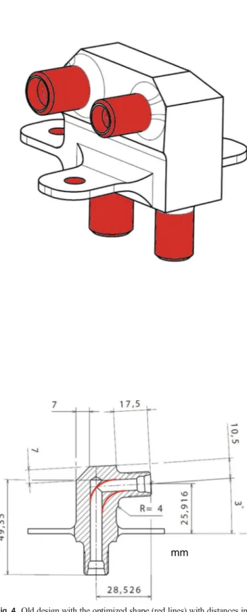
Hydraulic optimization: internal surfaces should be opti-mized in order to reduce pressure drops and thus increase global performance. The industrial context surrounding subcontracting companies does not always allow the use of computational fluid dynamics. So, the design change may just be inferred from simple rules. For example, in the hydraulic bloc, the internal pipes have a sudden ninety-degree change of angle, due to machining processes which allow only straight pipes. By smoothing this geometrical change and using a wider arc (Fig.4) of 12 mm, the singular pressure losses are highly reduced. Using regular and singular pressure loss ana-lytical equations [19], a 70% reduction in pressure losses has been estimated.
Thermal optimization Oil reaches a temperature of about 130 °C in an airplane hydraulic system, while the exterior temper-ature can be cold as − 60 °C. Despite the ability to use SLM for adding double wall insulation or cooling shapes, it is un-necessary to cool down the part because the Ti6Al4V is
mm
mm
Fig. 3 Hydraulic bloc schematic (units in mm)
mm
Fig. 4 Old design with the optimized shape (red lines) with distances in mm
known to properly handle the thermal stresses induced by the temperature difference between the air and the oil [20]. Such lightened parts, similar to Fig.8, have already been additively manufactured in an industrial context and tested under realis-tic conditions.
Assembly optimization Additive manufacturing is sometimes considered as a “monolithic design” [21] which reduces as-sembly constraints such as creating functional interface sur-faces, machining, additional weight (minimal interface thick-nesses, bolt, seal, etc.), assembly time and storage of multiple parts. In this study, a single part is considered; thus, assembly optimization could not be developed.
Manufacturing optimization It is not an easy task to determine if SLM additive manufacturing would reduce the total manufacturing cost or time, because from the subtractive manufacturing point of view, SLM is a very slow process and needs post process operations. But many assemblies and functions can be integrated into one part. SLM technology can also run 24/7 all year round with minimum surveillance. Sensor integration Another function integration is the sensor integration which gives a product the ability to gather life cycle data. This probability has not been investigated in this article but should always been considered.
The first steps of this DFAM method aim at improving the functional performances of a given part. At this stage, most of the functional surfaces are fixed.(Fig.5) The next step is to transform those surfaces into volumes, following a basic for-mula [16] defining the functional surfaces’ thickness (Table 1). Using Eq. (4), the functional surfaces’ (Fig. 4) thicknesses are the following:
Now that the mandatory volumes and the design volume are determined, the next step is to define the different con-straints. Three types of constraints have been identified which can be encountered by the part during its life cycle:
Specification constraints (from the end user) The hydraulic bloc would be mainly subjected to a pipe pressure of 31 MPa (Table2). The boundary condition in this case is the only screw passage in order to fix the part on the plane.
Manipulation constraints Two manipulation constraints have been identified which are the torque on the couplings while hydraulic pipes are connected to the bloc and then a pull-out force at the end of the couplings which represent a traction force on the couplings due to a pipe mounting.
Machining constraints The different machining steps are side roughing and finishing contouring of the couplings, out-side threading plus an extra almost non-cutting pass, inout-side conic shape using a shaped drill and outside edge chamfering (Fig.3). Cutting force on additively manufactured Ti6Al4V can be analytically approximal or as described in [22]. F.E.M. can also be considered and give precise information about time variations of the cutting forces. The vice constraints has a pressure on the two parallel surfaces.
3.3 Topology optimization model
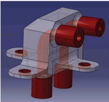
Now, all constraints, mandatory volumes and design volume are defined in the topology optimization algorithm which can be used. The next step is to choose precisely the objective and constraints of the optimization problem. A straight forward chosen objective function could have been the minimization Fig. 5 Mandatory volumes (red) and design volume (transparent)
Table 1 Thicknesses in function
of functional surfaces Functional surfaces
Minimal thickness T (mm)
Design variables used: T ≥ t + a/2 + emax; (a/2 = 0.1 mm)
Fixtures 1.5 T ≥ t = 1.4 mm (mechanical requirement) + a = 0.1 mm + 0 mm
Ducts 1.1 T ≥ t = 1 mm + a = 0.1 mm + 0 mm Couplings G4 3.2 T ≥ t = 1 mm + a = 0.1 mm + emax= 2.1 mm
of the mass with a maximum elastic stress for Ti6Al4V fa-tigue. Instead, in order to speed up the computation time and avoid mesh optimization during our two-software compari-son, a simple stiffness maximization with a 30% mass target has been considered.
For topological optimization, a very user-friendly software Inspire® and a more complex one Tosca® are used. More detailed results about this comparison have already been pub-lished [23]. The aim here is to help the designer and the ma-chinist to take together advantage of the natural variability of topologically optimal solutions.
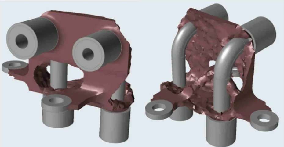
In order to obtain an optimal structural topology, one cal-culation is never enough, it is mandatory to explore meshing parameters but also boundary and load variants. The designer objective is generally to obtain one or several designs that are stable to small variations and easy to interpret as 100% filled and void regions. Figure6illustrates such result.
4 Additive and subtractive points of view
The final step of the method is mainly to confront the additive manufacturability and the machinability in order to find the best total cost.Additive manufacturability is extensively documented. Moreover, all software tends to include some additive manufacturing constraints in topological optimization.
The typical result of additive manufacturability analysis would lead to an orientation strategy, supporting strategy (see Fig.10), lasing strategy and post-processing strategy (thermal treatment, support removal, sand blasting, etc.), in order to reduce porosity, local defects, residual stress, deformation, build time, support removal effort and glob-ally cost.
As in Fig. 6 shown above, the optimized shape is not optimal in terms of machinability, because of low stiff-ness and because there is no clear surface for clamping the part during machining. The best mounting solution is usually using a vice which needs two parallel sur-faces and at least two points to block all directions. But sometimes, the vice solution is not possible and a discussion is needed with the machinist who needs to find the best solution. Here due to topology optimiza-tion, it is very hard to find sufficient surfaces to apply the statically determinate fixture. Here it would be typ-ically necessary to implement 6 contact points to fix the part, and thus the stiffness of the clamping would be quite low, compared with mounting on a vice.
As variability showed several optimal possible shapes, the machinist may propose here to add two functional surfaces and associated forces; to make possible the use of a vice, the result is illustrated in Fig.7. This new constraint has to be chosen wisely to minimize the economic impact on the total cost of the part.
Fig. 6 Topology optimization model after iterations
Table 2 Summary of constraints
on the hydraulic bloc Load and fixtures Source Value Location Pressure End-user specs 31 MPa Internal pipe walls Fixture End-user specs U1, U2, U3, UR1, UR2 = 0 Fixture surface
Vice Machining 20 MPa Parallel faces
Torque Manipulation 50 Nm Axe of couplings
Pull out force on couplings Manipulation 200 N Axe of couplings
For example, this new constraint would also strongly affect the supports needed during additive manufacturing, and their ability to be removed, as illustrated in Fig.10. Orientation of the part during AM may even be completely reconsidered.
In this particular case, the orientation during AM was strongly determined because the internal surface of the pipes needed to be self-supported. However, if the diameter had been considered small enough or if the cross section of the pipe had been considered as a design variable, the orientation would have been considered more freely and support minimi-zation would have been an important optimiminimi-zation factor.
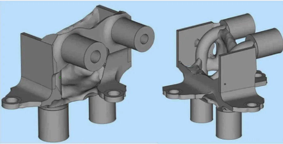
Using Inspire®, two designs have been created. The first (Fig. 7) is an optimal design to minimize the supports and avoid removing them in inaccessible zones. The initial mass of the machined part is 210 g. After topology optimization, the new mass is 95.5 g, but this ratio has been fixed for the sake of simplicity and software comparison; it is not an optimal weight.
A second design (Fig.8) has been performed, which is more oriented for optimizing the AM process time. The first design has more lasing time due to the shape of the part. This one has a smaller lasing time, but the shape of it is not completely optimal for the supports. The removal of some supports involves a complicated manufacturing process. As said before, the original mass of the hydraulic bloc is 210 g. Due to aeronautical specs, the first eigenfrequency must be
above 2500 Hz. But this added dynamic constraint has only been considered using Inspire® and not yet using Tosca®.
Each Inspire®-optimized design has its own pros and cons. But from the machinist’s point of view, the most optimal design to reduce machining process constraints is the first (Fig.7).
Using Tosca®, another optimized design (Fig.9) has been obtained respecting the same objective function and con-straints explained previously, including the two stressed planes for vice mounting. As previously explained, a main difference between the software would be the differences be-tween Eq. (2) and Eq. (3). The result shows a lack of material to link one of the fixture points, which shows how different algorithms may produce different optimal shapes. Compared with the previous software, because of the lack of a 3-points fixture, this design would not be considered as suitable for such part.
The subtractive and additive point of view should be con-sidered simultaneously, but a typical supporting strategy ob-tained with QuantAM Renishaw® Software, with the design obtained with Inspire software®, is illustrated in Fig.10. Due to the SLM process, the supports are made from the same material as the part. Titanium support’s removal is not an easy task; it typically needs the help of electro-portable tools or even machining. In comparison, aluminium supports can be easily removed using a clamp or even a flathead screwdriver. Fig. 7 First optimal Inspire®
design
Fig. 8 Second optimal Inspire® design
The colours of the supports, represented Fig.10, are asso-ciated with the way they are connected with the part, or to-gether, which has a great impact on their removability. A light blue support is not intersecting the part or another support, so it is very easy to remove. If dark blue, it is an isolated internal support, a bit more difficult to remove. If light red, it is intersecting with another support, usually to improve its stiff-ness, but it still quite easy to remove. On the contrary, dark red means that the central cylinder of the support is intersecting with the part, which should be avoided, because these sup-ports are very difficult to remove.
The initial part, obtained by milling machining, is manufactured in 40 min from a cubic shape raw. Considering an hourly rate of 70 €/h, the cost of the milling process alone is about 50 €. Considering that the price of titanium alloy Ti6Al4V grade 5 is 40 €/kg and that the raw
cubic shape weight is 1.5 kg, the cost of material is about 60 €. The cost of the machining fixture is not significant as the cubic shape allows the use of a vice, but several positions in the vice are necessary to obtain the final part.
For SLM additive manufacturing Ti6Al4V powder, cost is much higher, about 500 €/kg. Considering the powder really used, the material cost would only be around 100 €, for the optimized hydraulic block. The SLM machine has also a higher hourly rate, near 200 €/h, and building time would lead to a cost of about 400 €, including non-productive time.
The initial-machined design needs several machining phases; the last one is represented in Fig.11, with the two last threading. Such machining fixture represents an extra cost of a few hundred euros. For the first topologically optimized de-sign, Fig.6, this same machining fixture could be used and the same or a similar one for the two other threading. Because of the lower stiffness of the part, cutting condition should be reduced and at least take twice the time. Very often SLM parts need much more complex machining fixture to obtain an ac-ceptable stiffness for machining, and some parts may always very difficult to machine.
Fig. 9 Optimal Tosca® design
Fig. 10 Supporting strategy for the optimized part
Fig. 11 Complex machining fixture (a), the non-optimized (b) part and the milling tool (c)
On the other hand, the design topologically optimized for machining, Fig.8, would allow the use of a simple vice, illus-trated in Fig.12. There would not be any extra cost for ma-chining fixture, no cutting condition reductions and all the machining would be done in a unique phase. The machining duration is only 6 min which add a machining price of 7 € just in terms of hourly rate price.
Despite our optimization, the total cost of the SLM part is near 500 € and still much higher than the machined one, ≈ 100 €. Only the mass reduction and the hydraulic performance improvement could balance the over-cost. In the space indus-try, it is known that the cost to orbit is about 5–10 k€/kg. For the aeronautical industry, this ratio depends on the lifetime of the plane. A table given in [24] shows an annual saving of about 17 k€/kg/year. Moreover, it can be assumed that reduc-ing pressure losses on several parts on the hydraulic circuit
could lead to reduce the power of the pump and thus a mass reduction.
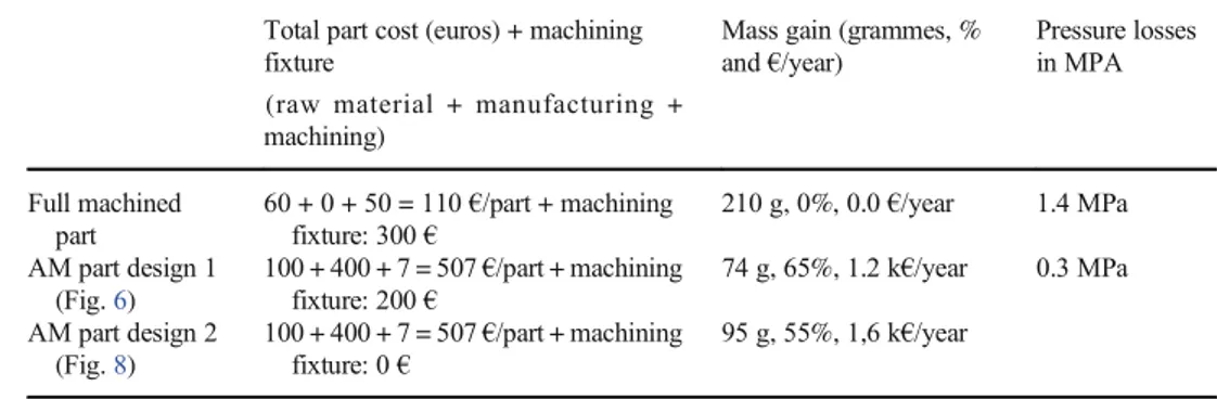
Table3compares the cost and benefits between the three designs considered. The one fully machined from a cubic raw, the one simply topologically optimized and the one also tak-ing into account machintak-ing constraints. Costs of the raw ma-terial, manufacturing, machining and machining fixture are detailed. The mass gain is given in grammes, percentages and annual saving, accordingly [24]. The pressure loss (de-tailed in [22]) is given for a typical 21 MPa input pressure, and as said before, it could also lead to mass gain for the pump, but it is difficult to quantify without a complete study of the hy-draulic circuit.
Indeed, Table3shows that taking into account the machin-ing constraints in such DfAM method keep most of mass reduction for such part, as well as an industrial process price reduction. The inherent overweight would have a non-negligible cost (0.4 k€/year), but it can be reduced by design-ing easily removable clampdesign-ing zones on the part.
What fundamentally differentiates our DfAM approach from the usual approaches has been highlighted in blue in Fig.2. The first step is to consider from the start the surfaces to be machined and to estimate the cutting forces. The next step is to explore the inherent variability of topological opti-mization algorithms in order to identify the design variants that are most compatible with machining, i.e. which allow the workpiece to be strongly held during machining (bending or even vibrations during machining would already be consid-ered in the topological optimization). Finally, it is necessary to optionally add functional surfaces and associated clamping forces, to obtain a part capable of being maintained in machin-ing under good productivity conditions. A fundamental point is that it is necessary to simultaneously validate additive and subtractive manufacturability, so that the two points of view converge towards a global optimal.
Indeed, it has been shown in Table3that taking into ac-count all the machining constraints in a DfAM method are allowing a mass reduction as well as an industrial process price reduction, so the final cost of the AM part can be re-duced. But the addition of functional surface and forces for the Fig. 12 Vice fixture with the optimized part
Table 3 Cost saving and part performances improvement between the 3 designs
Total part cost (euros) + machining fixture
(raw material + manufacturing + machining)
Mass gain (grammes, % and €/year) Pressure losses in MPA Full machined part 60 + 0 + 50 = 110 €/part + machining fixture: 300 € 210 g, 0%, 0.0 €/year 1.4 MPa AM part design 1 (Fig.6) 100 + 400 + 7 = 507 €/part + machining fixture: 200 € 74 g, 65%, 1.2 k€/year 0.3 MPa AM part design 2 (Fig.8) 100 + 400 + 7 = 507 €/part + machining fixture: 0 € 95 g, 55%, 1,6 k€/year
machining clamping naturally increases the weight of the part, but this could be compensated by designing removable clamping zones on the part.
5 Conclusion and perspectives
In this article, a proposal for a DfAM method including ma-chining issues has been made, since most of the metal parts manufactured additively require reworking and this must be considered at the design stage. This method has been con-cretely illustrated on a hydraulic part, representative of many parts likely to be manufactured additively within a few years’ time. This application case led to a design, quite similar to what is usually obtained in this context, but this time with a topological optimization of the machining phase.
It is important to remember that the proposed method ac-tually starts with an eligibility test, in order to avoid wasting time trying to optimize parts which are not suited for additive manufacturing. These simple criteria are dimensions compat-ible with the additive process considered, an available materi-al, a strong interest in saving weight and/or hydraulic (or oth-er) performance, a good knowledge of the loads during ma-chining, assembly/disassembly and the phase of use of the part, a sufficiently low criticality and a non-prohibitive cost compared with the current cost, to be worth a try.
In our example, which is representative of many aeronau-tical hydraulic parts, it should be noted that the machining forces are a priori the greatest efforts that the part sees throughout its lifecycle. So, if these efforts are neglected dur-ing design, either machindur-ing is almost impossible or it requires multiple precautions for holding the workpiece and/or to re-duce cutting forces, which can significantly affect the produc-tivity of the machining and therefore the total cost of the part. Again, it is the dialogue between the machinist and the addi-tive manufacturing specialist that can lead to the best compro-mise. For this particular part, the machining of the initial de-sign lasts 40 min, while the phases only necessary if one starts from a rough produced additive that last 6 min. Thus, reducing the machining efforts by a factor of 4 to adapt, for example, to a part four times more flexible, leads to quadrupling the ma-chining time from 6 to 24 min, which necessarily has a cost.
In perspective, this study may lead to several further studies:
– Our following research is naturally oriented towards manufacturing, machining, assembly and testing in real conditions. Progress on these subjects is made, and some of them will be published soon.
– Topological optimization may generate many variants, more or less suitable for additive and subtractive manufacturing, but only experts are able to explore them methodically, and this takes a lot of time. Rules related to
additive manufacturing are already implemented in some topological optimization software, such as maximum overhang angle. The implementation of rules for subtrac-tive machining, such as cutting forces and fixture zones, would help.
– The choice of supports, in additive manufacturing, al-ready respond to many constraints (ease of designing, resistance, thermal sink, minimization of the powder wasted, ease of being removed), but the ease of removing them by machining is barely studied at the design stage, while this would allow sorting among the many types of supports offered to the designers. This is currently being studied by our team and will be the subject of a next publication.
Acknowledgements The authors would like to thank the technical ser-vice of Cousso and Mr Jean-Pierre Garreau for their technical and finan-cial assistance and also thanks to Mr J-P Faye for his help using Abaqus. Finally, the authors want to thanks “la région Occitanie” for their financial support on CEF3D.
References
1. Kruth J-P (1991) Material increase manufacturing by rapid prototyping techniques. CIRP Ann 40:603–614
2. Levy GN, Schindel R, Kruth JP (2003) Rapid manufacturing and rapid tooling with layer manufacturing (LM) technologies: state of the art and future perspectives. CIRP Ann-Manuf Techn 52:589– 609
3. Kruth JP, Mercelis P, van Vaerenbergh J, Froyen L, Rombouts M (2005) Binding mechanisms in selective laser sintering and selec-tive laser melting. Rapid Prototyp J 11 1:26–36
4. Pessard E, Mognol P, Hascoët JY, Gerometta C (2008) Complex cast parts with rapid tooling: rapid manufacturing point of view. Int J Adv Manuf Technol 39:898–904
5. Kranz J, Herzog D, Emmelmann C (2015) Design guidelines for laser additive manufacturing of lightweight structures in TiAl6V4. J Laser Appl 27:S14001
6. Horn TJ, Harryson OLA (2012) Overview of current additive manufacturing technologies and selected applications. Sci Prog 95(3):255–282
7. Guo N, Leu MC (2013) Additive manufacturing: technology, ap-plications and research needs. Front Mech Eng 8:215–243 8. Bendsøe MP (1989) Optimal shape design as a material distribution
problem. Struct Optim 1:193–202
9. Zhou M, Rozvany GIN (1991) The COC algorithm, Part II: Topological, geometrical and generalized shape optimization. Comput Methods Appl Mech Eng 89:309–336
10. Stolpe M, Svanberg K (2001) An alternative interpolation scheme for minimum compliance topology optimization. Struct Multidiscip Optim 22:116–124
11. Boothroyd G, Alting G (1992) Design for assembly and disassem-bly. CIRP Ann 41:625–636
12. Kerbrat O, Mognol P, Hascoët JY (2011) A new DFM approach to combine machining and additive manufacturing. Comput Ind 62: 684–692
13. Rosen DW (2007) Design for additive manufacturing: a method to explore unexplored regions of the design space, 18th Annual SFF symposium
14. Gibson I, Rosen DW, Stucker B (2010) Design for additive manufacturing. in: additive manufacturing technologies. Springer US, pp 283–316.https://doi.org/10.1007/978-1-4419-1120-9_11
15. Kumke M, Watschke H, Vietor T (2016) A new methodological framework for design for additive manufacturing. Virtual Phys Prototyp 11:3–19
16. Ponche R, Hascoet JY, Kerbrat O, Mognol P (2012) A new global approach to design for additive manufacturing. Virtual Phys Prototype 7:93–105
17. Vayre B, Vignat F, Villeneuve F (2012) Designing for additive manufacturing. Procedia CIRP 3:632–637
18. Reiher T, Lindemann C, Jahnke U, Deppe G, Koch R (2017) Holistic approach for industrializing AM technology: from part selection to test and verification. Progress Additive Manuf.
https://doi.org/10.1007/s40964-017-0018-y
19. Benoist V, Arnaud L, Baili M, Faye J-P (2018) opological optimi-zation design for additive manufacturing taking into account flexion and vibrations during machining post processing. HSM 2018 20. Mertens A, Reginster S, Paydas H, Contrepois Q, Dormal T,
Lemaire O, Lecomte-Beckers J (2014) Mechanical properties of
alloy Ti-6Al-4v and of stainless steel 316 L processed by selective laser melting: influence of out equilibrium microstructures. Powder Metall 57:184–189
21. Reiher T, Koch R (2016) Product optimization with and for additive manufacturing, 27th annual international solid free from fabrication symposium
22. Benoist V, Arnaud L,Baili M, Faye JP (2018) Improved design methodology for additive manufacturing including machining load 619 cases: application to an aeronautical workpiece. MUGV2018 23. Benoist V, Baili M, Arnaud L (2019) Design for additive
manufacturing including machining constraints: a case study of topology optimization including machining forces. IMMAT2019 (hal-02359933)
24. Gilani M, Körpe DS (2019) Airline weight reduction to minimize direct operating cost, 4thInternational Aviation Management