UNIVERSITE DE SHERBROOKE Faculte de genie
Departement de genie mecanique
MODELISATION DE LA PERTE PAR
TRANSMISSION DES PAROIS LEGERES A
DOUBLE PANNEAUX
Memoire de maitrise Specialite : genie mecanique
Julien LEGAULT
Jury : Noureddine ATALLA (directeur) Stephane MOREAU
Alain BERRY
Sherbrooke (Quebec) Canada Juillet 2010
1*1
Published Heritage Branch 395 Wellington Street Ottawa ON MAOISM Canada Direction du Patrimoine de I'edition 395, rue Wellington Ottawa ON K1A 0N4 CanadaYour file Votre reference ISBN: 978-0-494-70767-Our file Notre reference ISBN:
978-0-494-70767-NOTICE: AVIS:
The author has granted a
non-exclusive license allowing Library and Archives Canada to reproduce,
publish, archive, preserve, conserve, communicate to the public by
telecommunication or on the Internet, loan, distribute and sell theses
worldwide, for commercial or non-commercial purposes, in microform, paper, electronic and/or any other formats.
L'auteur a accorde une licence non exclusive permettant a la Bibliotheque et Archives Canada de reproduire, publier, archiver, sauvegarder, conserver, transmettre au public par telecommunication ou par I'lntemet, preter, distribuer et vendre des theses partout dans le monde, a des fins commerciales ou autres, sur support microforme, papier, electronique et/ou autres formats.
The author retains copyright ownership and moral rights in this thesis. Neither the thesis nor substantial extracts from it may be printed or otherwise reproduced without the author's permission.
L'auteur conserve la propriete du droit d'auteur et des droits moraux qui protege cette these. Ni la these ni des extraits substantiels de celle-ci ne doivent etre imprimes ou autrement reproduits sans son autorisation.
In compliance with the Canadian Privacy Act some supporting forms may have been removed from this thesis.
Conformement a la loi canadienne sur la protection de la vie privee, quelques formulaires secondaires ont ete enleves de cette these.
While these forms may be included in the document page count, their removal does not represent any loss of content from the thesis.
Bien que ces formulaires aient inclus dans la pagination, il n'y aura aucun contenu manquant.
1+1
RESUME
Pour faire face aux imperatifs de diminution du poids des avions et des helicopteres tout en maintenant le contort acoustique a Pinterieur des appareils, les solutions de controle du bruit doivent etre elaborees des les premieres phases de la conception. Pour assister les ingenieurs dans cette tache, ce projet vise a developper un modele analytique rapide et precis pour la prediction de la transmission sonore a travers les parois aeronautiques a double panneaux (murs lateraux des cabines d'avion). La strategic de modelisation utilisee est basee sur l'hypothese d'une structure infinie et periodique.
Tout d'abord, une configuration composee de deux plaques metalliques connectees par des poutres en C est etudiee. Les modeles simples existant dans la litterature sont implements et une approche periodique est developpee. Ces modeles et cette approche sont ensuite compares a une experience de validation. Les resultats montrent que les modeles simples sont mal adaptes aux structures legeres, car la plupart de ces modeles ont ete originalement concus pour les murs du domaine de la construction. En contrepartie, 1'approche periodique concorde bien avec les mesures.
Au chapitre suivant, 1'approche periodique est modifiee pour prendre en compte les structures composites et les liens resilients discrets reliant le panneau interne au panneau externe. A l'aide du modele developpe, plusieurs etudes parametriques sont conduites sur les proprietes dynamiques des liens, sur l'absorption dans la cavite et sur l'amortissement des panneaux. Grace a ces etudes, des conclusions pratiques pour les concepteurs sont tirees, notamment au niveau de la pertinence d'attenuer la transmission structurelle entre les panneaux a l'aide de liens resilients. L'approche periodique est aussi comparee a des calculs par elements finis et une bonne concordance est obtenue.
Au dernier chapitre, il est montre comment les traitements multicouches remplissant la cavite entre les panneaux peuvent etre integres dans le cadre de l'approche periodique. Un exemple est donne pour un traitement a trois couches.
Dans le cadre de la presente maitrise, deux articles ont ete publies dans le Journal of Sound
and Vibration ([43],[55]) et un troisieme article sera soumis a V Acoustical Society of America.
Mots-cles : acoustique, vibration, aeronautique, transmission sonore
REMERCIEMENTS
Je tiens tout d'abord a remercier mon superviseur et mentor, M. Noureddine Atalla, pour toute la confiance qu'il ma accordee. Sous sa supervision, j'ai la conviction d'etre devenu un scientifique plus complet et de m'etre depasse. J'espere un jour pouvoir atteindre un niveau de connaissance aussi exceptionnel que le sien. De plus, je le remercie sincerement de m'avoir permis de participer a de nombreuses conferences et colloques lors de mes deux ans au GAUS. Enfin, je souhaite lui temoigner toute ma gratitude pour son support lors de mes demarches d'application au doctorat a Tuniversite Cambridge. Je suis convaincu que ses lettres de reference et ses bons mots auront fait la difference. Ayant etudie sous son aile, j'apprehende le defi du doctorat avec confiance et optimisme.
Mes remerciements s'adressent egalement aux gens du GAUS : a Maxime Bolduc, pour m'avoir invite a joindre l'equipe de recherche et pour son amitie au cours de toutes ces annees, a Celse Kafui Amedin, pour son aide technique et scientifique, a tous les professeurs qui m'ont enseigne aux etudes superieures (Raymond Panneton, Denis Gingras, Alain Berry et bien d'autres), pour la grande qualite de leur enseignement, et a tous les membres etudiants et non-etudiants du GAUS, pour leur plaisante compagnie lors de mon passage parmi le groupe.
A mes amis et a ma famille : merci pour tout votre support et votre comprehension lors de ces deux annees d'etudes. Vous etes plus que jamais importants a mes yeux.
Enfin, je tiens a remercier le CRSNG pour m'avoir remis la bourse d'etudes superieures Alexandre Graham-Bell. Grace a cet appui financier, j'ai pu mettre l'accent sur mes etudes et me consacrer entierement a mon projet de recherche.
TABLE DES MATIERES
RESUME i REMERCIEMENTS iii
LISTE DES FIGURES vii LISTE DES TABLEAUX ix LISTE DES ACRONYMES xi CHAPITRE1 INTRODUCTION 1
1.1 Mise en contexte 1 1.2 Definition du projet de recherche 2
1.3 Objectifs du projet de recherche 4
1.4 Structure du document 5 CHAPITRE 2 APPROCHES DECOUPLERS ET MODELE PERIODIQUE SIMPLE 7
2.1 Details bibliographiques et avant-propos 7
2.2 Article principal 8 CHAPITRE 3 MODELE PERIODIQUE ELABORE 39
3.1 Details bibliographiques et avant-propos 39
3.2 Article principal.... 40 CHAPITRE 4 PRISE EN COMPTE DES TRAITEMENTS MULTICOUCHES 72
4.1 Details bibliographiques et avant-propos 72
4.2 Article principal 73 CHAPITRE 5 CONCLUSION ET PERSPECTIVES 87
5.1 Synthese des approches developpees 87
5.2 Contributions originales 88
5.3 Travaux futurs 88 LISTE DES REFERENCES 91
LISTE DES FIGURES
Figure 1.1 : Transmission sonore atravers laparoi laterale d'un avion 3
Figure 1.2 : Vue explosee de laparoi laterale 3
Figure 1.3 : Liens resilients 4 Figure 2.2 : Pressure wave impinging upon the double wall partition 13
Figure 2.1 : The studied double wall structure: (a) complete structure; (b) first panel missing 13
Figure 2.3 : Measured Values vs. decoupled Approaches 32 Figure 2.4 : Effect of mass on Fahy's and Davy's approaches 33
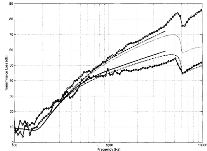
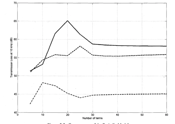
Figure 2.5 : Convergence of the Periodic Model 34 Figure 2.6 : Measured Values vs. Periodic Model 36
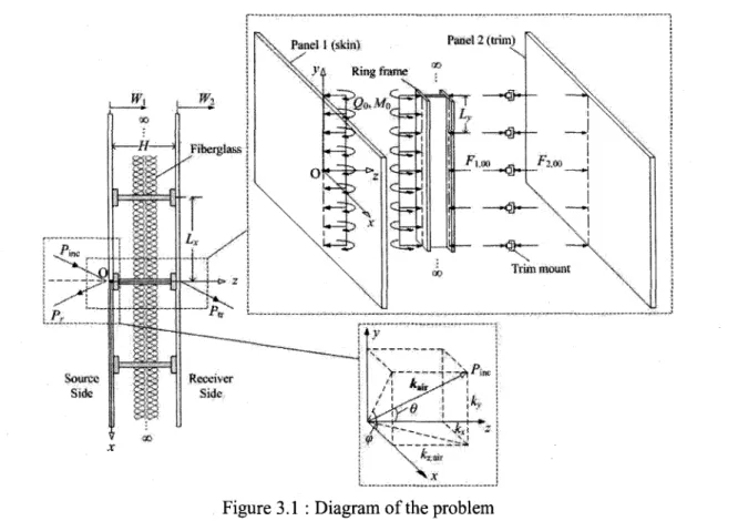
Figure 3.1 : Diagram of the problem 46 Figure 3.2 : The influence of mount stiffness (metallic configuration) 58
Figure 3.3 : The influence of mount stiffness (composite configuration) 59
Figure 3.4 : Structural transmissibility vs. transmission loss 61 Figure 3.5 : The influence of mount damping (composite configuration) 62
Figure 3.6 : The influence of mount spacing (composite configuration) 63 Figure 3.7 : The influence of cavity absorption (composite configuration) 64 Figure 3.8 : The influence of panel damping (composite configuration) 66
Figure 3.9 : Periodic Model vs. FEM-Line connections 68 Figure 3.10 : Periodic Model vs. FEM - Rigid and massless point connections 68
Figure 3.11 : Periodic Model vs. FEM - Point connections with Kmouat = 106 Nm"1 and mm0Unt =
0.01kg 69 Figure 4.1 : Diagram of the problem 76
Figure 4.2 : Three layer NCT example 80 Figure 4.3 : Numerical results: mount stiffness vs. cavity absorption 86
LISTE DES TABLEAUX
Table 2.1 : Dynamic Properties of the Fibrous Material (Property, Value) 12 Table 2.2 : Properties of the C-Section Channels (Property, Symbol, Value) 12
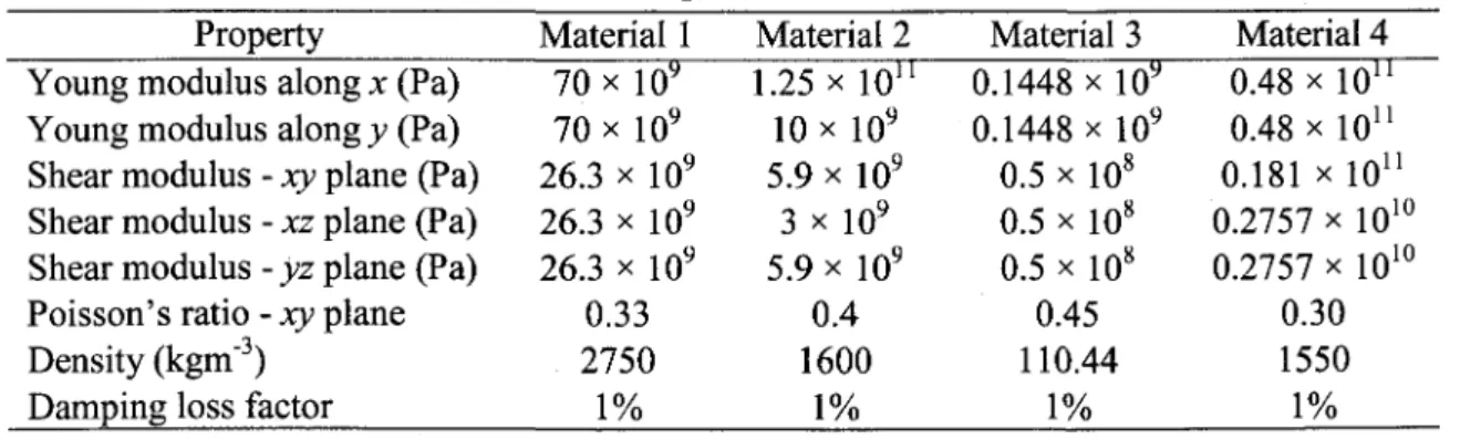
Table 3.1 : Material properties used for the panels 56 Table 3.2 : Dynamic properties of the fibrous material (property, value) 57
Table 4.1 : Porous-elastic material properties used for the noise control treatments 84
LISTE DES ACRONYMES
Acronyme SEA FEM BEM dB NCT TMM TBL CRSNG GAUS DefinitionStatistical Energy Analysis Finite Element Method Boundary Element Method
Decibel
Noise Control Treatment Transfer Matrix Methodology
Turbulent Boundary Layer Conseil de Recherche en Sciences
Naturelles et Genie du Canada Groupe d'Acoustique de l'Universite de Sherbrooke
1.1 Mise en contexte
Dans le domaine de l'aeronautique, les ingenieurs sont systematiquement appeles a reduire le poids des appareils afin de diminuer la consommation de carburant. Pour faire face a ce defi, ceux-ci font de plus en plus appel aux materiaux composites, car en plus d'etre plus legers, ils offrent une plus grande rigidite structurale et une plus longue duree de vie en fatigue (meilleure resistance a la propagation des fissures). A titre d'exemple, la peau des avions, qui etait traditionnellement faite a partir d'une plaque d'aluminium raidie d'une epaisseur variant de 40 a 60 milliemes de pouce (environ 1 mm), a deja ete remplacee par des panneaux composites dans plusieurs modeles commerciaux (Boeing 787, Bombardier Learjet 85, etc.).
Au niveau de l'isolation vibratoire et acoustique, l'utilisation de ces panneaux pose deux grands defis qui se doivent d'etre releves, car la vibration du fuselage des appareils ainsi que le confort acoustique en cabine sont des enjeux tout aussi majeurs que le poids des appareils pour la competitivite des entreprises. Premierement, en reduisant la masse des parois de la structure a l'aide des materiaux composites, le potentiel d'isolation sonore est aussi reduit. En effet, une loi acoustique de base, c'est-a-dire la loi de masse, stipule que plus la masse d'une paroi est grande, plus la transmission sonore a travers celle-ci sera faible. Heureusement, cette loi ne s'applique pas dans toutes les situations, car pour le meme poids, certains materiaux sont beaucoup plus efficaces que d'autres en terme d'isolation (mousses acoustiques, materiaux viscoelastiques, etc.). Par consequent, l'utilisation de ces materiaux s'avere crucial pour ne pas perdre l'avantage de la reduction de poids des composites a cause des imperatifs de confort acoustique en cabine. Deuxiemement, il adonne egalement que pour leur poids, les panneaux composites sont parmi les moins performants en termes d'isolation acoustique en raison de leur rigidite et du phenomene de coincidence structural-acoustique [1]. Cela renforce 1'importance de concevoir des traitements acoustiques adequats pour l'utilisation de ces panneaux.
Pour assister les ingenieurs dans cette tache, des outils de modelisation se doivent d'etre developpes. Cette these de maitrise s'inscrit done dans ce contexte. Elle a ete realisee dans le cadre de la chaire de recherche industrielle du CRSNG en acoustique appliquee a 1'aviation detenue par les professeurs Noureddine Atalla, Alain Berry et Stephane Moreau.
2 INTRODUCTION
1.2 Definition du projet de recherche
Une composante importante de l'avion sur laquelle beaucoup d'efforts se doivent d'etre investis afin de contrdler efficacement le bruit en cabine est le mur lateral, communement appele Sidewall Panel en anglais. Ce mur a double panneaux est compose d'un panneau externe principal raidi (Skin Panel) et d'un panneau interne (Trim Panel) qui vient s'attacher aux raidisseurs circonferentiels (Ring Frames) du panneau principal a l'aide de liens resilients
(Trim Mounts). Dans la cavite formee entre les deux panneaux (celle-ci possede une epaisseur
de l'ordre de 2 a 3 pouce), un traitement acoustique compose de plusieurs mousses isolantes est insere (Noise Control Treatment). La figure 1.1 illustre ces propos a l'aide d'une vue en coupe schematique d'une section de fuselage tandis que la figure 1.2 montre une vue explosee tridimensionnelle. Enfin, la figure 1.3 montre a quoi ressemblent les liens resilients en pratique.
En vol, plusieurs types d'excitations s'exercent sur le panneau externe. Les principales sources sont la pression parietale aleatoire exercee par la couche limite turbulente (Turbulent
Boundary Layer), le bruit de la turbosoufflante et la vibration induite par les rotors. Tel
qu'illustre a la figure 1.1, l'energie est transmise du panneau externe au panneau interne a travers le chemin acoustique fluide (transmission acoustique ou airborne transmission en anglais) et a travers les liens structuraux entre les panneaux (transmission solidienne ou
structure-borne transmission en anglais). Elle est ensuite rayonnee en cabine. Si les liens
resilients entre les panneaux sont mal concus, la transmission acoustique en moyennes et hautes frequences sera dominee par le chemin structural et le traitement acoustique aura done peu d'impact a ces frequences. Une bonne conception doit s'assurer que le chemin acoustique soit dominant afin d'utiliser le traitement acoustique a son plein potentiel.
Actuellement, un modele analytique simple ou complexe n'a pas ete presente dans la litterature pour une structure ayant toutes ces caracteristiques (panneaux externe et interne composites, raidisseurs circonferentiels, joints resilients et traitement acoustique multicouches). En fait, la plupart des modeles existants qui traitent d'une structure s'approchant de cette configuration utilisent des methodes numeriques comme l'approche FEM-BEM. Ces methodes donnent generalement de bons resultats, mais le cout eleve en termes de temps de calcul les rend inappropriees pour pouvoir faire une optimisation numerique ou pour des calculs de conception preliminaire, car leur implementation requiert
souvent de tres grandes capacites de calcul. Par consequent, il serait important que les ingenieurs disposent de modeles analytiques leur permettant de conduire ce genre de travaux sur leurs propres ordinateurs. Cela constitue le sujet de cette etude, c'est-a-dire la modelisation analytique de la transmission sonore a travers les parois aeronautiques a double panneaux.
Turbulent boundary layer (TBL) pressure Rotor induced f\ f\j, vibration ^ t Turbofan noise Ring Frames Sound Treatment Package Trim Panel Structure-home transmission 1 1 1 i I 1 <*» Airborne transmission
Figure 1.1: Transmission sonore a travers la paroi laterale d'un avion
gTjjg* J~ '|i||||||MW^ "f:H|.-* J»-j« m?
*mm
WMmSSm WSBSBssmsSH
L
4 INTRODUCTION
Figure 1.3 : Liens resilients
1.3 Objectifs du projet de recherche
L'objectif principal de ce projet est le developpement d'un modele analytique pour la prediction de la transmission sonore a travers les structures aeronautiques a double panneaux. Les sous-objectifs principaux du projet sont:
1. La revue de la litterature et la comparaison des modeles simples existants;
2. L'elaboration d'un modele pour structures metalliques infinies a double paroi periodiquement connectees par des liens lineiques et la validation experimental; 3. L'extension a des structures composites avec joints resilients («trim mounts») discrets
entre les panneaux;
4. La validation numerique du modele;
5. L'integration des traitements multicouches;
6. *La prise en compte de l'effet des dimensions finies;
7. *L'extension du modele periodique a des excitations mecaniques aleatoires comme la couche limite turbulente.
*Au moment de l'ecriture et de la remise de ce memoire, les objectifs 6 et 7 sont toujours en cours de realisation. Ceux-ci seront inclus dans un rapport de recherche separe qui sera presente a la fin de l'ete 2010. Ce rapport servira a l'elaboration d'un quatrieme et dernier article.
1.4 Structure du document
Le present document a ete divise en cinq chapitres, soit 1'introduction, les trois chapitres du developpement correspondant aux trois articles publies dans le cadre de cette maitrise et enfin, la conclusion. Dans le premier chapitre, le contexte du projet et ses objectifs principaux ont ete introduits. Toutefois, le lecteur aura note qu'une revue de la litterature en francais n'a pas ete incluse, car celle-ci correspondrait a un simple resume francais de 1'introduction des articles (elle serait done redondante).
Le deuxieme chapitre contient l'article relie aux sous-objectifs 1 et 2 du projet [43]. Tout d'abord la problematique ainsi que la litterature pertinente sont situees et la structure experimental utilisee pour la validation des modeles theoriques est decrite. Ensuite, une description des principaux modeles simples pour la prediction de la transmission solidienne a travers les murs a double parois est realisee (les hypotheses sous-jacentes a chacun que de ces modeles sont discutees et analysees). Un modele periodique simple base sur plusieurs approches existantes est egalement formule mathematiquement. Dans la section resultats, les modeles simples et le modele periodique sont compares aux resultats experimentaux. Le tout se termine par une discussion critique des similarites et differences entres les modeles et l'experience.
Au troisieme chapitre, l'article relie au troisieme sous-objectif est presente [55]. La facon dont les panneaux composites peuvent etre traites par le modele periodique a partir des equations de dispersion des panneaux est premierement decrite. Ensuite, le developpement mathematique du modele pour la prise en compte des liens discrets entre le panneau interne et des raidisseurs circonferentiels est detaille. A partir du modele developpe, des etudes parametriques sont conduites sur l'effet des proprietes dynamiques des liens, de l'absorption dans la cavite et de l'amortissement des panneaux. Le tout est suivi d'une validation du modele a l'aide d'un calcul par elements finis et d'une discussion critique.
Le quatrieme chapitre est une extension du modele presente au troisieme chapitre pour prendre en compte les traitements multicouches dans la cavite entre les panneaux (dans l'article du troisieme chapitre, la cavite est remplie par un seul materiau). Les principaux resultats du chapitre precedent y sont repris et la facon dont les traitements multicouches avec materiaux poro-elastiques peuvent etre incorpores dans le modele periodique est detaillee. Cette methode fait appel aux matrices de transfert. Un exemple numerique est aussi donne.
6 INTRODUCTION L'article de ce chapitre sera prochainement soumis au Journal of the Acoustical Society of
America.
Enfin, au dernier chapitre, une synthese des approches developpees dans la presente maitrise est faite et l'apport des travaux a l'avancement des connaissances techniques et theoriques est commente. Le tout se termine par une description des perspectives futures a court et long terme.
MODELE PERIODIQUE SIMPLE
2.1 Details bibliographiques et avant-propos
S Auteurs et affiliation :• Julien Legault (etudiant a la maitrise, Universite de Sherbrooke, Faculte de genie, departement de genie mecanique)
• Noureddine Atalla (professeur, Universite de Sherbrooke, Faculte de genie, departement de genie mecanique)
•S Date d'acceptation : 18 fevrier 2009
•S Etat de l'acceptation : version finale publiee
•S Revue : Journal of Sound and Vibration
S Reference : [J. Legault, N. Atalla, Numerical and experimental investigation of the effect
of structural links on the sound transmission of a lightweight double panel structure,
Journal of Sound and Vibration, vol. 324 (2009), p. 712-732]
S Titre francais : Etude numerique et experimental de l'effet des liens structuraux sur la
perte par transmission sonore des parois legeres a double panneaux
S Contribution au document: voir resume francais ci-dessous
S Resume francais :
Cet article examine plusieurs modeles predisant 1'influence des liens structuraux periodiquement espaces sur la perte par transmission sonore des parois legeres a double panneaux. Une structure composee de deux plaques d'aluminium liees par des poutres en C ou la cavite entre les plaques a ete remplie de fibre de verre a ete construite et sa perte par transmission mesuree pour la comparaison et la validation des approches a l'etude. Tout d'abord, les approches classiques decouplers sont decrites et adaptees pour le probleme. Un modele periodique base sur des formulations existantes est ensuite presente. Le modele prend en compte un champ excitatoire acoustique tri-dimensionnel et la fibre de verre dans la cavite est modelisee a l'aide d'un fluide equivalent. Trois approximations sont presentees pour la modelisation des liens structuraux: une approximation de type masse-ressort-masse, une approximation de type poutre et une approximation de type
8 APPROCHES DECOUPLERS ET MODELE PERIODIQUE SIMPLE
poutre ou la rigidite et l'inertie des poutres est negligee. Les mesures montrent que les liens structuraux reduisent considerablement la perte par transmission et la presence de pics et de creux caracteristiques des structures periodiques est aussi observee. Les predictions faites a partir des approches decouplers ne reproduisent que partiellement les tendances observees et lorsque la masse des liens est prise en compte, leur ecart avec les mesures se creuse davantage. A l'oppose, la concordance entre les mesures et les resultats obtenus avec le modele periodique est excellente sur presque toute la plage de frequences. Toutefois, autour de la frequence critique du panneau le plus epais (6 kHz), la perte par transmission est sur-estimee. Cela suggere que le modele devra etre modifie pour mieux prendre en compte l'amortissement et la transmission resonante.
•S Note : Le numero des equations, des figures et des tableaux de Particle original ont ete
modifies afin d'harmoniser 1'article avec le present manuscrit.
2.2 Article principal
Numerical and experimental investigation of the effect of structural
links on the sound transmission of a lightweight double panel structure
Julien Legault, Noureddine Atalla
Abstract
This paper examines various models predicting the influence of periodically spaced structural links on sound transmission through lightweight double panel structures. A baseline configuration made up from two aluminum plates connected through aluminum C-section channels and a fiberglass filled cavity has been specifically built and its TL measured for comparison and validation of the investigated models. First, classical decoupled approaches are outlined and adapted for the studied case. Next, a periodic model based on existing formulations is presented. The model allows for a 3D incident field and accounts for the absorption in the cavity with the help of an equivalent fluid model for the fiberglass. Three cases of coupling conditions are considered for the links: a mass-spring-mass approximation, a beam-type approximation and a beam-type approximation where the rigidity and the inertia of the beams are neglected. The measurements show that the bridged configuration strongly reduces the TL at mid and high frequency and exhibits pass/stop bands characteristic of periodic structures. The predictions of decoupled approaches capture the physics of the problem only approximately and with the integration of the mass of the connectors in the context of thin lightweight panels, their agreement with experimental data is further reduced. On the other hand, the results obtained with the periodic model are excellent over most of the studied frequency range. However, in the vicinity of the critical frequency of the thicker panel (around 6 kHz), an overestimation of the TL is observed. This suggests that the model will have to account better for damping and resonant transmission.
1. Introduction
Double panel structures filled with air or absorbent fiberglass can be found in a wide range of applications and were therefore extensively studied in the literature. A recent article by Hongisto [2] provided a detailed comparison of the prevalent models for the prediction of sound transmission through such constructions. Over the 20 models presented, only a few
10 APPROCHES DECOUPLEES ET MODELE PERIODIQUE SIMPLE
were able to deal with connections between the panels: Sharp [3]-[4], Gu and Wang [5], Fahy [6] and Davy [7]-[8]. In these four models, the problem was addressed by decoupling the total transmission in terms of a fluid-borne path through the cavity and a structure-borne path through the connectors. They will be referred here as "decoupled approaches".
Yet, many other types of formulations were developed to include the effect of structural links. Among them, approaches taking advantage of the periodicity of the structure were presented by several authors. In the latter, the equations of motion of the plates include the reactions of the connectors in addition to the pressures due to fluid loading. To solve the associated systems, two methods are classically used. The first method was introduced by Mead and Pujara [9]-[10] and consists of representing the response of the structure in terms of a series of space-harmonics. The principle of virtual work is then applied on one period of the system to solve its dynamics. Lee and Kim [11] employed this technique to study the radiation of a single stiffened plate subjected to a plane wave excitation. Wang et al. [12] extended the approach to double-leaf partitions connected through vertical resilient studs. Urusovskii [13] had previously studied the problem using space-harmonic series to represent the plates' response, but he assumed rigid studs and did not use the principle of virtual work to formulate the dynamics. Instead, he introduced the "phase factor" associated with the force exerted on the plates by the stud as a result of oblique incidence in the equations of motion. The second method makes use of Fourier transform techniques. This is the case of Lin and Garrelick [14] who calculated sound transmission through double-plate structures attached periodically by rigid connectors. To study radiation under mechanical excitation forces of point connected, point connected with rib stiffening and rib connected structures, Takahashi [15] used the Fourier transform as well, but his equations did not include fluid loading. Ultimately, even if the solving procedure behind the two approaches is not similar, both lead to solutions in which the response is given as a series of space harmonics [16].
When simulations or experimental validations were conducted in the above-mentioned references, attention was principally focused on building constructions which are typically composed of plasterboard panels connected with wooden studs or metallic channels. Although they are not strictly equivalent to these structures, lightweight aircraft sidewall panels are good examples of double panel partitions since they are frequently made of periodically rib-connected panels with fiberglass in-between. Moreover, the rivets attaching the ribs to the
plates and/or the trim mounts are close-spaced to provide stiffness. In comparison, the distance between the screws or nails used to bond the plasterboard panels to the wooden/metallic skeleton in buildings is normally larger. Craik and Smith [17] discussed the fact that when this spacing is small, the connection can be modeled by a continuous line. However, when it gets larger, each point can be assumed independent and so the coupling may be modeled as a series of independent point connections. The appropriate transition frequency between these two regimes occurs when a half bending wave-length on the plate fits between the nails or the screws. Considering the above-mentioned differences, using experimental or simulations results of building partitions may not be adequate to validate the performance of classical prediction models for lightweight double wall systems with periodic connections. The aim of this paper is therefore to examine experimentally and numerically the effect of periodically spaced mechanical links on the transmission loss of a double panel structure that is more representative of aircraft applications.
First, the studied structure is described (geometry, dimensions, connection details, etc.). Next, the decoupled approaches [2]-[7] presented in Ref. [2] are outlined and adapted to the studied case. Afterwards, a periodic model integrating important features of previous models [9]-[15] is exploited and extended to account for the nature of the studied mechanical link and cavity absorption. This is done by using an equivalent fluid model for the fibrous material [18]. A result section in which the studied models are compared to measurements is finally presented. It is followed by a general discussion on the accuracy of the various prediction methods.
2. Preliminary considerations
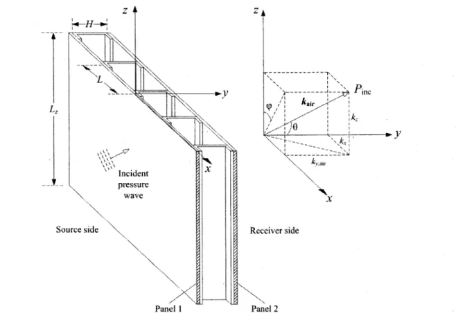
2.1 The studied structure
Figs. 2.1 and 2.2 present the double wall system studied throughout this document. It is made up from two 1220 mm x 2030 mm aluminum plates (1 mm thick and 2 mm thick) separated by a 50.8 mm cavity filled with a fibrous material. The Biot acoustic properties of the material (porosity, flow resistivity, tortuosity and characteristic lengths) were measured at the Universite de Sherbrooke's acoustic materials characterization lab using direct methods (anisotropy is neglected and only the properties in the through thickness direction were measured). They are given in table 2.1 and will be used in the equivalent fluid model of the
12 APPROCHES DECOUPLEES ET MODELE PERIODIQUE SIMPLE material [18]. The aluminum panels are linked with five "C-section" channels (also in aluminum), each spaced by a distance L of 508 mm. The thickness eg of the channels is 3.175 mm, while their web length H measures 50.8 mm and their flange length Lp measures 25.4 mm. They have a Young modulus EB of 70 x 109 Nm"2, a Poisson's ratio vg of 0.33 and a
density ps of 2742 kgm"3. Using these geometrical and mechanical properties, equivalent
section properties of the channels were computed with the help of text books formulas [19]. They are given in table 2.2. To attach the channels to the panels, 76.2 mm spaced screws were used. The holes were threaded and nuts were employed to tighten the assembly. However, the exact torque was not measured. In addition, a layer of silicone was used between the surface of the channels and the panels to approximate a full line coupling condition, i.e. to reduce the impact of discrete screw spacing.
It is certain that with such attributes, the studied structure does not render all the complexity found in real aircraft constructions (curved panels, composite trim, possibility of a multilayer sound package, added constrained layer damping, isolating mounts, etc.). However, it represents a simple and realistic case study for the proposed models comparison.
Table 2.1 : Dynamic Properties of the Fibrous Material (Property, Value)
Density of the fluid phase 1.21 kgm"3 Tortuosity 1.0
Speed of sound in the fluid phase 342 ms"1 Viscous Length 128><10"6m
Flow Resistivity 17.7 kNms"4 Thermal Length 376*10"6m
Porosity 0.91 Density of the solid phase 35.0 kgm"3
Table 2.2 : Properties of the C-Section Channels (Property, Symbol, Value) Mass per unit length
Second moment of area with respect to the x axial axis (see Fig. 2) Distance between the section centroid and section shear center Moment of inertia per unit length in the z direction with respect to centroidal axial axis
Moment of inertia per unit length in the z direction with respect to shear center axial axis
Torsional constant in the z direction
Torsion-bending section constant associated to warping
niB Ix Cx /o h Jz
r
8.85 x 10"1 kgm"1 1.39 x 10"7m4 15.9 x l0"3m 1.76 x lO^kgm 3.98 x 10"4 kgm 1.21 x 10"V4 9.79 x 10"12 m6Figure 2.1 : The studied double wall structure: (a) complete structure; (b) first panel missing
Source side
Panel 2
Figure 2.2 : Pressure wave impinging upon the double wall partition
Fig. 2.2 presents a schematic of the studied problem. It represents an acoustical plane wave Pinc impinging on the source side (panel 1) of the double wall assembly. The incident wave
makes an angle 6 with they axis and its projection in the xz plane makes an angle (p with the z axis. Its amplitude is PQ and its wavenumber ka\r can be decomposed in the x, y and z directions:
14 APPROCHES DECOUPLEES ET MODELE PERIODIQUE SIMPLE ^nC = ^o e xP[-JK ~ )kyMry - jkzz], (2.1) where: — sin 0 cos (p (2.2) * „ * = — c o s 0 , (2.3) c„ir kz= — sin 6 sin <p . (2.4)
The time dependence factor exp(jcot) was omitted in Eq. (2.1) and will be considered implicit henceforth. Air with density /)air (1.21 kgm"3) is present on both sides of the partition and the
associated speed of sound is cajr (342 ms"'). The effective density of the fiberglass filling the
cavity is pcav and the effective speed of sound and wavenumber in that fiber are, respectively,
ccav and kcav (&cav = co/ccav). Note that by using an equivalent fluid approach for the fiberglass,
Pcav, ccav and £Cav are complex and frequency dependent [18]. When the incident wave hits the
partition, a reflected wave Pr is created in the source region and a wave PtT is transmitted into
the receiver side. Inside the cavity, the pressure is Pcw. The two panels, whose displacements
are noted W\ and Wi and velocities vi and vi, respectively have thicknesses e\ and ei of 1mm (first panel, source side) and 2mm (second panel, receiving side). They both have Young modulus's E\ and E2 of 70 x 109 Nm"2, Poisson's ratios vi and v2 of 0.33, internal damping
ratios //jnt)i and tjmt,2 of 1% and densities p\ and p2 of 2742 kgm"3. With these parameters, it is
possible to calculate the mass per unit area m,-", the bending stiffness Z)„ the impedance Zp.,
and the critical frequency fCTti of the z'th panel [6]:
m^pfi, (2.5) 12(l-v,2) ' ( } z , = j < o / « ;
i_A*,
4 m"a2 (2.7) <L \m" co„^
=7Jn
=f'
(2-
8)With the presented values, the critical frequencies are therefore around 12 kHz for the 1mm panel and around 6 kHz for the 2mm panel. Accordingly, a dip is expected in the transmission loss curve around 6 kHz. In practice, these dips are however highly sensitive to cavity and edge damping. The critical frequency of the 1mm panel will not be captured in the presented study since TL measurements were taken in 1/12 octave bands from 100 Hz to 10 kHz for both configurations (coupled and uncoupled). During the experiments, the edges of the wall were clamped on the mounting frame with wooden bars. To reduce the structural leaks to their minimum, neoprene was inserted between the two parts of that frame (receiving and source sides) all along the perimeter.
Finally, it is worth mentioning that for modeling purposes, the connecting channels will be considered transparent to the acoustic waves in the cavity; meaning the effects of lateral resonances in the cavity will be disregarded (cavity is not partitioned). In future work, it will be important to investigate this aspect of the problem; but at the present stage, it is not necessary since none of the studied models addresses this issue.
3. Decoupled approaches
3.1 Methodology
This section explains the simplified modeling methodology used in the decoupled approaches. On the source side of the double panel, an incident plane wave with acoustic power Ilin induces motion of the first panel. This motion creates a pressure inside the cavity and drives the structural bridges connecting the panels. Energy can therefore travel from the first panel to the second via two separate paths: the fluid-borne path through the cavity (energy transmission coefficient ic) and the structure-borne path through the bridges (energy transmission coefficient %B). The fundamental assumption of decoupled approaches is that these paths are independent and additive. Hence, the acoustic power emitted by the second panel nout corresponds to the power radiated by the panel due to the action of bridges YlB plus
the power radiated due to the action of the cavity pressure nc. The total transmission loss of
the system TLtot can thus be written:
= -101og[rc+r5], (2.9)
TL„ -lOlog n„
n.
= -101og16 APPROCHES DECOUPLERS ET MODELE PERIODIQUE SIMPLE
At low frequencies, fluid-borne transmission is generally dominant and the bridged partition behaves similarly to the uncoupled one. However, at mid and high frequencies, the structural path prevails and reduces the TL considerably. The transition frequency between these two regimes is called the bridge frequency^ and corresponds to the point when Ilg reaches nc.
In the following section, a calculation procedure for the fluid-borne transmission in the absence of bridges will be detailed. During the presented numerical simulations, this procedure will be common to all decoupled approaches even though the original authors of these approaches have presented their own view on this path. Attention will, therefore, be concentrated on structure-borne sound transmission formulations. This will render comparison easier between models by eliminating sources of discrepancy. Besides, it should not have a significant impact at mid and high frequencies since the structural path is dominant.
3.2 Fluid-borne transmission
When the line junctions are absent and the panels are modeled by thin infinite plates in bending, the analysis reduces to a 2D pattern in which q> = JI/2. Using the transfer matrix method (TMM) [20], the pressures and velocities at the forward and backward faces of the double wall system are related by:
= T T T Jl l J1 2 T T (2.10) where: T = 1 Z p,i 0 1
«»(w0 j f ^ H w )
y,cav k j ^ ^ L s i n ^ c a v( W O ™(K*»
H) 1 Z P.2 0 1 (2.11)Px = Pinc + Pr is the pressure on the receiving plate, (2.12) ^>,cav = v^cav _ ^x ^s m e acoustic wavenumber inside the cavity. (2.13)
Making use of the global transfer matrix T, the fluid-borne transmissibility tc(6) at a given angle 6 is given by:
• ( * ) = \ + R \Tn+TjZ» where: R = Pr _ Z-Zu Z =
K
=Tn
Z*
+Tn
Vl TlAc+T22 j _ fjr_ _ _AiirCai v2 cos 6* (2.14) (2.15) (2.16) (2.17)The diffuse field transmissibilityrc can be obtained by integrating over 6 with the appropriate
weighting [6]:
Tc ~ J Tc(&)sin0cos0d0 / J sin^cos^cft?, (2.18)
where #nm = 90° for random incidence and #nm ~ 78° for field incidence transmission.
3.3 Structure-borne transmission models
3.3.1 Sharp
In Refs. [3] and [4], Sharp formulated the problem of sound transmission through a double wall by using a decoupled approach. In his handling of the structure-borne path,, he began by rewriting Eq. (2.9):
TLt o t=-101og
n
c+ n
g :TLc-101og 1 + —M- (2.19)where TLc is the transmission loss of the isolated partition. For lie, he employed the expression of the power radiated by an infinite plate exposed to a sound field at normal incidence (0 = 0):
nc~p^Svl (2.20)
where S is the area of the panel. For the near field radiation of sound bridges, he relied on Heckl's theory [21]:
18 APPROCHES DECOUPLEES ET MODELE PERIODIQUE SIMPLE
where VB is the rms velocity of the area K over which the force induced in the second panel by the sound bridge is acting. For a line force, which is the studied case,
K _ 2L\mAcr,2 (2.22)
7C
where Acr^ is the critical wavelength of the second panel and L\ine is the length of the line
connection. In the present situation, Lyme corresponds to the height of the wall Lz. If there are q
equally spaced line junctions between the panels, S = q-L-Lz and:
n
B2qLA
FL 'cr,2 ItS VV2 V 2C,;r.. \
nLfc cr,2 V Vl J f \ \VU (2.23) Sharp assumed that the velocity of the first panel was unaffected by the introduction of the line connection. Thereby, the ratio v\/v2 in Eq. (2.23) corresponds to the velocity ratio of the panels in the absence of bridges (vi and vj are the panel velocities). For frequencies below critical frequencies of both panels, he reduced this ratio to the following expression by making few simplifications: ^ vv 2y ( (£>2m"2H ^ com air air / ft -/mam J JIf>f,
air air / C. 2nH (2.24) (2.25) where: f = J mam 1 1.8/^c, 271* 2 rm"+m"^ H \ mlm"i jis the mass-air-mass frequency [3]. (2.26)
In Eq. (2.26), the factor 1.8 was introduced to account for the finite dimensions of the panels. Besides being limited to frequencies below the critical frequencies of both panels, the above formula was also developed by assuming air was present inside and outside the cavity. Thus, for the purpose of the problem addressed in this paper, a less restrictive expression will be employed by substituting Eq. (2.10) into Eq. (2.23) with 6 = 0:
v,
— = 7 T +T :cos(£cav//) + jsin(£cav//)
Z -, + o c A^cav ci
(2.27) Sharp also assumed the connectors were rigid and massless. Combining this hypothesis with the analysis of the force induced in the bridge by the first panel, he showed that the ratio vglv\ could be written:
B _ . Aine,l
7 + 7 (2.28)
Zl i n e„ . = 2 D >1V3 / 4( l + J)> (2-29)
where Ziine,i corresponds to the line impedance of the rth plate [6]. At that point, he combined
Eqs. (2.19), (2.23), (2.24), (2.28) and (2.29), inserted values of air for the fluid inside and outside the cavity to reduce the TL formula to its simplest expression. The obtained TL curve in the presence of line connections was parallel to the mass law above the bridge frequency fa. Sharp also added a positive empirical correction of 5dB to the curve after this point. The need for this correction was explained by the fact that assuming the response of the first panel is unaffected by the introduction of line connections is not accurate. In reality, the mass of the connectors and the impedance of the second panel exert a non-negligible influence that reduces the velocity of the panel. Yet, this correction will not be applied in this paper since it was intended to improve the modeling of panels bonded by connectors typically used in building constructions, i.e. wooden studs much heavier than the lightweight aluminum channels employed in the studied structure. Hence, Eq. (2.23) will be applied integrally except for the modified expression of the ratio v\/v2 (Eq. (2.27)).
3.3.2 Gu and Wang
To enhance the accuracy of predictions for double wall constructions linked with metallic channels showing a bending resilient character, Gu and Wang extended Sharp's theory by modeling the connection as a spring of equivalent translational stiffness Ks [5]. In the presence of flexible bridge connections, velocities VB\ and vgi on each side of a bridge are not equal. Consequently, Eq. (2.23) was reformulated by inserting the ratio VBIIVB\\
EL 2qLl
n
r 'z cr,2 TlS 21 'cr,2 VV2 J TtL "B\ Vvi J VB1 \ 2 / \2 KVBIJ \V2J (2.30)20 APPROCHES DECOUPLEES ET MODELE PERIODIQUE SIMPLE
To evaluate this ratio, Gu and Wang regarded the problem as a classical mass-spring-mass system, where masses M\ and Mi are related to the effective masses of the panels (the mass of the connection was not considered). This leads to:
V_B1_ KVB\J l - o o V K. t j K. vco2M2 y when co » (2.31)
Cremer and Heckl [22] showed that when a panel is excited by a line force and the length of the line is much larger than the width of the radiation area, the effective radiation area of the panel is approximately rectangular and its width is Aair/2. Accordingly, Gu and Wang proposed
the following expression for M2.
Mn
m"X • L
2air• z
CO
(2.32) Inserting Eq. (2.32) into Eq. (2.31), the following ratio VS2/VBI is obtained:
r V r K:
(2.33) where Kt' is the equivalent translational stiffness per unit length (K,' = Kt/Lz) of the connector.
For V1/V2, they used Sharp's formula while assuming vB\/vi = 1. Then, they combined Eqs.
(2.19), (2.24), (2.30) and (2.33) and inserted the values of air for the fluid inside and outside the cavity to calculate the transmission loss. However, they did not apply the 5dB correction Sharp introduced to account for the modified response of the first panel.
To estimate Kt' for the current configuration, two approaches can be applied. First, if the
bending character of the channels is considered, it can be assumed that the bending force FB
acts along the middle of the flange. Moreover, it can also be assumed that the major contribution to the deformation comes from the bending in the web of the channel. Knowing that the moment is equal to FBLF/2 in the web, the static translational stiffness per unit length is
E e3
3HL2F
(2.34) For the studied channels, K/ = 22.8 x 10⁶ Nm"2, which is in good agreement with the order of
magnitude suggested in Ref. [5]. On the other hand, it would also be realistic to neglect the contribution of bending, because the added silicone layer should reduce the flange
deformations and thus reduce the lever inducing bending in the web. In that case, the principal deformation would come from the axial deformation in the web and the static translational stiffness per unit length becomes:
K',=^, (2-35)
ti
which leads to a much stiffer value of 4.375 x 10⁹ Nm"2. Since Gu and Wang's model was
developed for flexible connectors, the estimation accounting for bending will be employed and the second estimation will be employed for other models. Yet, the outcome will still probably not be satisfactory, because the simplification Gu and Wang assumed for the ratio VBTJVBX at Eq. (2.33) will only be met above a few thousand hertz with the current parameters:
<D» \£-=>/»—£ = 613Hz. (2.36)
This was to be expected since the model was developed for building wall types where the value of m-i" is generally much higher. Finally, note that for the implementation of the Gu and Wang model, Sharp's expression for the ratio v\lvi will once again be replaced by Eq. (2.27).
3.3.3 Fahy
The approach developed by Fahy is concurrently similar and different from Sharp's. As implicitly stated in the model of Sharp, Fahy assumed the dynamics of each stud independent of the others and their motion limited to the translation induced by incident bending waves normal to the stud-leaf connection lines. However, instead of using the ratio nB/TIc to express
the degradation of transmission loss caused by the presence of structural connections, he relied on the blocked pressure approximation to estimate directly the response of the first panel:
Px * 2F>nc * Zp,lVl * jcomfc when / « /CT>1. (2.37)
This approximation inherently ignores the influence of the studs over the panel response and is also only valid when fluid loading effects are neglected. Assuming the panels identical (Ziine;i
= Ziine,2 = Z\\ae) and taking the mass per unit length of the stud mB' into account, Fahy expressed
the stud (or bridge) velocity vB induced by the first panel as follows:
22 APPROCHES DECOUPLERS ET MODELE PERIODIQUE SIMPLE
When ms' is neglected and the line impedances of the two panels are different, this formula corresponds to Eq. (2.28) of Sharp's model. Finally, as Sharp did for lis, Fahy used the expression of the near field radiation power of a line force excited panel at frequencies below critical frequencies of panels [6]:
2 I I2 I | 2
j - j _ A i r I^21 _ AirFline,2Vfl| _ A i r InlineVB\ ,« - „ .
B 4(wff)2(0 4(m")2w 4(m")2co '
where Fi is the effective force per unit length applied by the stud on the second panel. Considering that there are q' connections per unit length (q' = ML) [6]:
TB(e) = 2q'Uf™Cak • (2.40)
l^ncl COS0
At that point, he inserted Eqs. (2.37) to (2.39) into (2.40) and neglected the impedance of the stud for practical building construction cases, to reduce TB(0) to:
**(*)= ¥&**'> <
2
-
4i
>
V3co psecost>
where pS; Q and e represent the density, quasi-longitudinal wave speed and thickness of the
plate material, respectively. He also computed the ratio of this transmissibility to the one given by the oblique mass law part of the fluid-borne path rmass_iaw(#):
TB(&) _ TB{&) _ 2cos0q'ec, _ 0.7cos0q^c^_ „ ^
rmass-law ( # ) ( Pa i rCa i r /(dm" COS df -Jlc^ fa
This expression is independent of frequency, indicating that the TL curve in the presence of line connections is parallel to the mass law as in Sharp's model.
In the presented results, the model of Fahy will be implemented integrally expect for Eq. (2.38) where different line impedances for the panels will be allowed. This means Eq. (2.41) will not be used. However, the mass of the connection will still be neglected even though it should not be so; for the studied case, at frequencies of interest (audio frequencies), the line impedances of the panels have a similar order of magnitude compared to the mass' impedance.
As Gu and Wang's model is an extension of Sharp's for flexible connectors, Davy [7]-[8] relied on Fahy's theory and allowed the bridge to depict a resilient character. He also allowed the panels to have different line impedances. Thereby, when the mechanical compliance per unit length CM {CM = 1/A7) of the bridge is taken into account and half of the bridge mass mB'
is attributed to each panel (mass-spring-mass system), the velocity vB2 of the bridge on the side
of the second panel is:
v = zune,ivi : (2 4 3 )
82 Znne,, + [ l - K / 2 ) C >2] [ Zl i n e > 2 + jcom;] + j c o C ^ Z ^ Z , ^ -(m'Jl^Z^ca2
Yet, the most interesting aspect of Davy's approach is the fact that he addressed the problem of resonant responses of the panels, thus allowing his model to be applied in the vicinity and above their critical frequencies. First, he used the fact that for each panel the energy ratio d\ of the resonant to the non-resonant forced (mass controlled) response is given by [23]
nco er.
where CT, represents the single sided radiation efficiency of the panel and //toy its total loss factor. The latter is equal to the sum of the internal loss factor rjmXj and twice the single sided
radiation loss factor ?/radt, (//tot,; = 2%^ + f/int,;)- The single sided radiation loss factor is related
to the single sided radiation efficiency:
^=E^~L- (2-45)
com,.
Next, Davy utilized the ratio r{ of the sound power radiated by the resonant vibration to the sound power radiated by the forced near field vibration of a line force on the fth panel [24]:
^ (2.46) 2/7tot, V co
The combined effect of the resonant response and radiation are summarized in the factor Q:
e=(i+4ow)(i+>-high), (2-47)
where the subscript low refers to the panel having the lowest critical frequency and the subscript high to the panel having the highest critical frequency. This procedure was introduced to remove the apparent asymmetry. To compute a, Davy relied on the corrected
24 APPROCHES DECOUPLEES ET MODELE PEPJODIQUE SIMPLE T B=-^PIAQ g2+(4co1-5m1"m2Va,rCA/'-g2)2 g = Wl VC° c r , 2 + 'W2 V( 0c r , l • Leo2
version of Maidanik's formulae given by Ver and Holmer [25]. For both plates, he limited the maximum value of o to one to agree better with the sound transmission prediction of third octave band of noise.
Combining Eqs. (2.44) to (2.47) with (2.37), (2.39) and (2.40) and with (2.43) instead of (2.38), using the correction factor Q, integrating over 6 (Eq. (2.18)) with 6\xm = jt/2 and
neglecting ms in Eq. (2.43), Davy obtained the following diffuse field transmission coefficient:
(2.48)
(2.49) For the results of this paper, Davy's model will be implemented integrally except for the integration limit 6\\m that will be 78° instead of 90° (see section 5.2). Thus, even though the
mass impedance ms' is not negligible in comparison to the line impedances of the panels (see section 3.3.3), the latter is still neglected. For radiation efficiency calculations, the corrected version of Maidanik's formulae given by Ver and Holmer [25] will be employed and the dimensions of the sub-panels (1016mm x 1220 mm) delimited by the channels adjacent to the line force will be used instead of the ones of the whole wall (2030 mm x 1220mm). The maximum value of the radiation efficiency will be limited to one for both plates as Davy suggested.
4. Periodic approach
4.2 Derivation of the model
To provide a comprehensive periodic approach for the studied case, the reaction forces of the connectors applied to the panels in the x and z directions should be included which requires a refinement of the panels' model. Besides, geometrical features such as finite size of the wall and discrete screw fixing of the channels should also be considered. Due to this added complexity and given the scope of this study, the infinite thin plate in bending model will be conserved. Therefore, in addition to fluid loading, the panels are only subjected to forces per unit length F\t„ and F2,n normal to the stud-leaf connection lines applied by the connectors at x
= nL and to moments per unit length M\<n and M2,» in the z direction. The two panels'
equations of motion consequently take the following form:
[ A V4 - c o V ] Wx = {Pmc + Pr - Pcav )|| - X F^x - nL) + dx +00 ps [ A V4 - co2m'f\W2 = (Pcav - PtT )|| - J ] F2,„5(* nL) + -5x
l M
u5 ( . - n L )
l——oo 0 I W1 (8 ( j t - n L ) , (2.50) , (2.51) d4 84 d4 wwhere V4 =—j + 2—-—r- + —-r, To lighten the notation, let X = X • The response of the dx dx dz dz *-><—!
n n=-co
panels can be expressed as an infinite sum of "space-harmonics" [9],[10],[26]:
^ = Z
UU
eXP [-J Kn
X~ JM ] ,
n wi = Z
M2,« exp[-j^„x-JM ] ,
n where, 2n%Kn=K+-(2.52) (2.53) (2.54)
Similarly, the pressures inside and outside the cavity can be represented by space-harmonic series [10]:
n
P<*. = I X e xp [ - j ( ^ + ^,cav,„>' + ^ ^ ) ] + A exp[-j(^„x-^iCav>„y + kzz) ] , (2.56)
n
P
tr = S « . « P [ - J ( * ^ + * ^ 3 ' + M ) ] .(
2-
57)
where, Ky,ah,n ~ yjKiar Kx,n Kz > (2.58) (2.59) k - It-2 -k2 -k2Since the structure is periodic in the x direction, forces and moments both satisfy the periodicity relation [26]:
26 APPROCHES DECOUPLEES ET MODELE PEPJODIQUE SIMPLE
M . „ = M ,0e x p [ - j ^ ] - (2.61)
In addition, Poisson's formula allows writing the sum of the 8 functions as follows:
^ 5 ( x - « L ) = - £ e x p -2]nwc (2.62)
Combining Eqs. (2.60), (2.61) and (2.62) yields:
p. £ ^ , „ 8 ( x - n £ ) = -i£exp[-j*,x]]Texp -2jmcc L -2)mvc
= - f Z
e xp [ - J ^ ] . <
2-
63)
L M, ^ £ e x p [ - j ^ „ x ] . (2.64) Y,Min5(x-nL) = —^exp[-j^x]£exp « L, nThe factor exp[-j£xx] in the above equations corresponds to the phase factor introduced by
Urusovskii in Ref. [13]. Finally, continuity conditions at fluid-panel interfaces require that:
e(^„e + Pr) By 3/>cav dy 3/Lv Sy
SK
dy y=0 y=H y=H ^PJTi, y=0 :<»Vcav^> = v>2PmW2, <»2pa«w2 (2.65) (2.66) (2.67) (2.68)Substituting Eqs. (2.55) to (2.57) into Eqs. (2.65) to (2.68) and using the fact that the sums must be true for all values of x, the pressure coefficients and displacement amplitude coefficients are related for each n:
e»=PA- J<» AnrMl,„
M ^ c s c f e , ^ ) / r . , „ - | \ «» = ^ 7 ( e x p ^ j ^ cav nH\ux „ -u2n),
y,cav,n
R fi)2Pcavcsc(^cav„//)/
(2.69)
(2.70)
4 =
jcoya i rexp[j^a M//]M 2 t„ y,air,n
(2.72)
where 80 = 1 and 8„ = 0 for n + 0. Inserting Eqs. (2.63), (2.64) and (2.69) to (2.72) into Eqs.
(2.50) and (2.51) and requiring the sums to be true for all values of x, two.coupled linear equations are obtained for each n:
where, A,,„ A„ K A2,„ *2,n 2Pn5 1,0 iK,nMXfi 0"n L L F2fi JKr,M2,0 L L
^Di^tf-ntf^^^'"^-A
2,
n=D
2(kl
n+k>)-my
+^
+ j(02Pair , fflVcavCOt(^>cav>„//)
k k
y,air,n y,ca\,n
A„ 0>VcavC S C(^,cav,n#)
(2.73)
(2.74)
(2.75)
(2.76)
By manipulating Eq. (2.73), explicit expressions of u\,„ and «2,« are obtained:
1,B *2,n V V . 2 ^0A2, A ' -2^oA„8n + Kn(FX»+}KnMX$) ( A» (F2 . 0 + J ^ , ^ 2 , o ) L L K (FXfi + }kx,„Ml,0 ) \ n (*2,0 + J ^ , „M2 , 0 ) where, V „ = A , A , „ - ^ . (2.77) (2.78) (2.79) Summing Eqs. (2.77) and (2.78) over all n, a matrix system analogous to the one presented in Ref. [26] can be built:
Wn
w
x dWjdx W2 dWjdx = x=0\s
u S2ls
n Su S22 •$32 ^42 5,3 ^ 2 3 ^33 ^ 4 3 S,41 •J24 ^34 ^44 ' Fi,o " MU 0 1 2,0 M2 , 0 + 2P0 V0 A2,o "J^,oA2,o ~ \ J^,oAo SF0 + P0, ( 2 . 8 0 )28 APPROCHES DECOUPLEES ET MODELE PERIODIQUE SIMPLE
where Wo, Fo and Po represent the displacement, force and excitation vectors, respectively. The coefficients Sy of the S matrix are given by:
(2.81)
To complete the solution, the reactions acting along the connection line at x = 0 have to be expressed in function of the panel displacements and slopes at that particular location. In the following sections, three coupling cases are described.
i
z-~Kn J^,nA2,„ K _-J*»,A iK,n"-2s -k2 A J**A k2 A x,n n K -)K,nK ~\n iKnKn J^.A k2 A x,n n ~)K,n\n -k2 A
4.2 Derivation of the model
4.2.1 The general coupling case
A general coupling condition requires that the force and displacement vectors Fo and Wo are linked by a dynamic stiffness matrix K:
F0 = *Lo 1 2,0 _M2 , 0 _ = * . . K2l * 3 . K4l Kn K22 K32 KA2 Kn K, 14 24 34 44_ wx dWjdx W2 8W2/dx = KWn (2.82)
In this matrix, the terms K,j are function of the inertial and resilient properties of the connectors. They can be found by modeling the links with lumped elements [12], by using FEM to account for more complex behavior (ex: presence of modes; complex geometry) or from experimental measurements. Once known, Eqs. (2.80) and (2.82) can be combined, leading to the following system of equations:
[I4-KS]F0=KP0, (2.83)
where I4 is the 4 * 4 identity matrix. Having found forces F,-,o and moments M,;o, the latter can be substituted back into Eqs. (2.77) and (2.78) to find ui,„ and u2,„ for each n. The coefficients £,„ of the transmitted pressure are then obtained through Eq. (2.72) and used to calculate the
transmission coefficient TP(d,<p) of the periodic model [12]:
ZI^|2Re(^a,r,«)
\P\ k
|J0 | "".y.air
At first sight, the implementation of this whole procedure may seem cumbersome, but instead of solving a 2 x (2n + 1 ) matrix system by replacing the expressions of reactions into Eq. (2.73), computations are reduced to sums and the resolution of a 4 x 4 system. The diffuse field transmission coefficient is finally calculated by integrating Tp(6,(p) over 6 and cp [6]:
2ir 3i m it/2 t J \ Tp(O,<p)sin0cos6>d0d<p J j Tp(6,(p)sin6cosOdGdq> 0 0 2TI «,in J J sm.0cosOdOdcp 0 0 urn J sin6cos&d0dcp (2.85)
4.2.2 The mass-spring-mass approximation
To a first approximation, a mass-spring-mass system with constants independent of kz and
where forces are decoupled from slopes and moments decoupled from displacements can be used to model the connecting channels. In translation, the static stiffness K,' (Eq. (2.35)) of the channels is employed and it is assumed half of the mass mB' is located on each panel (lumped
masses). In rotation, a similar scheme is also applied: the inertia term corresponds to Io (see table 2.2) and the static rotational stiffness per unit length K/ corresponds to the bending rigidity per unit length of the channel web:
r H Y1H
(2.86)
where I'z is the second moment of area per unit length of the web with respect to the z axial
axis. In the present case, Kr'= 3.675 x 10³ Nm r a d ' W . The stiffness matrix Kthus takes the
following form: K = -0.5m'Bo)2 0
-K
0 +K; 0 - 0 . 5 /Oc o2 + K'r 0-K
-K
0 -0.5m>2 + K\ 0 0-K
0 -o.5/0co2+/:; (2.87)It is worth noting that with the current mass-spring-mass approximation in translation and rotation, the model presented here would be equivalent to the one developed in Ref [12] if: (i) the cavity was empty (not filled with fiberglass), (ii) the rotational inertia was neglected and (iii) the integration was reduced to a 2D pattern in which q> = nil.
30 APPROCHES DECOUPLEES ET MODELE PERIODIQUE SIMPLE
In fact, even though the wavenumber kz is absent in the rigidity matrix K, the integration
with respect to heading angle <p remains necessary since the propagation factors kXi„ of the
space harmonics vary with <p (see Eq. (2.54)). This means the TL will as well vary with (p even though the angle 6 remains the same (this is similar to orthotropic behavior).
4.2.3 The beam-type coupling case
Another possibility is to assume the channels behave like beams stiffeners. In that case, continuity requires that:
W =
w
dWjdx x=0 = W, 2,0
W,
dWjdx = W = VTB0
x=0 8Wjdx_
which implies from Eq. (2.80) that:
SUF1 , 0 + S12F2,0 + Pl = S21F1,0 + S22F2,0 + P2 > where, (2.88) (2.89) S„ = 5,, 5,2 521 S12 F.,0 = 1,0 M, 1,0 S„ = L2,0 5,3 514 523 524 2,0 M. 2,0 S„ = 2P rl _
v
n ^31 ^32 541 542 "^•2,0 "J^,0A S22 -533 534 543 544 2,0 2PP
2= ~
2 Vn -A0 J^,oAo (2.90)Defining K B as the beam dynamic stiffness matrix and using properties of a general beam stiffener [27]: F + F = K W rl , 0 r2,0 J VB " l BO ' , . 2 EBIxkz~m> -cxm'B(£>2 EDTkA+GJk2-Lu>2 WB, dWjdx_ (2.91)
The constants in the matrix KB are defined in table 2. Combining Eqs. (2.88) to (2.91), the
following 2><2 matrix systems are obtained and solved for Fi,o and F2,o:
X o =
-l2 ' KBS1 1 + (^2 " KBS1 2 ) (S2 2 " S12 ) (Sl l " S21 )
KBP1+(I2-KBS1 2)(S2 2-S1 2)-1(P2-P1)
^ - K B S U + C Z ^ K B S I O I S H - S Z I ) (S2 2 -Sn )
KBP1-(I2-KBS1 1)(S1 1-S2 1)-1(P2-P1)
where I2 is the 2 x 2 identity matrix. The procedure described in the general coupling case is then used to calculate the diffuse field transmission coefficient.
F2,0 =
-, (2.92)
4.2.4 The special case of non-rigid and massless beam connections
When all the rigidity and the inertia of the connecting beams is neglected (KB = 0), reactions on both sides of the beam become equal and opposite and Eqs. (2.92) and (2.93) yield:
F., ="FV =(S„ +S2 2-S1 2-S2 1)-1(P2-P1 ). (2.94)
5. Results
5.1 Experimental results
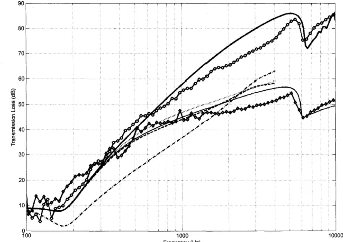
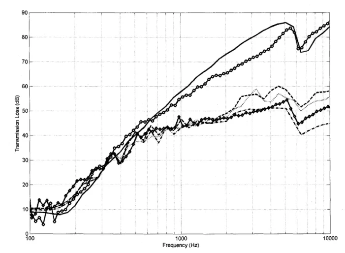
Fig. 2.3 presents the measured transmission loss of the uncoupled and coupled configurations (i.e. with and without line junctions). Predictions using the presented decoupled approaches are also shown together with the prediction of the fluid-borne transmission path through the cavity (decoupled configuration). Comparing the two experimental curves, it is seen as expected that the structural path strongly reduces the TL at mid and high frequencies (f> 300 Hz). A dip associated to the critical frequency of the second panel (6 kHz) is observed in both curves. The coupled configuration also exhibits a dip around 400 Hz. Finally, at low frequencies (f < 300 Hz), the TL of the coupled configuration is higher. This is probably caused by the additional mass and/or stiffness provided by the junctions, even though that mass and rigidity is not distributed over the panels. However, results below 200 Hz should be discarded because of the volume limitation of the used transmission loss suite.
5.2 Decoupled approaches
The results of the comparison between the studied decoupled approaches and measurements are in Fig. 2.3. In the presented simulations, transmission loss is calculated in 1/24 octave bands with a diffuse field integration limit #i;m of 78°. Since the models of Sharp, Gu and
Wang and Fahy cannot be applied above the critical frequency of either panel, they are plotted up to two-thirds of the critical frequency of the thicker panel. First, it is observed that overall the comparison between measurement and prediction for the fluid path (decoupled configuration) is satisfactory even though an overestimation is observed at mid to high frequencies. However, further investigation of the causes of this difference is not pursued since this is not important for the coupled configuration where the structure-borne transmission through the connectors is the dominant effect at these frequencies.
32 APPROCHES DECOUPLEES ET MODELE PERIODIQUE SIMPLE 90 80 70 60 g 5 0 o '(A £ 40 (/» c £5 i -30 20 10 100 1000 Frequency (Hz) 10000
Figure 2.3 : Measured Values vs. decoupled Approaches
o measured values (no junctions); 0 measured values (with junctions); — no Junctions (fluid-borne transmission only); Sharp; • — • — • Gu and Wang; Fahy; — Davy At first sight, the models of Sharp and Fahy appear fairly similar. Their prediction of the bridge frequency (fs ~ 300 Hz) is practically equal and in good agreement with both measurement and Davy's model. This is expected since equations in both models are similar except for the blocked pressure approximation in Fahy's approach. Above fs, the growth rate of the two curves is 6 dB per octave as anticipated. The fact that Sharp's curve is not totally straight is due to the use of the modified expression for v\hi. Above the bridge frequency and up to 2 kHz, the agreement with measurement is acceptable for Sharp and Fahy's models and good for Davy's model. In fact Davy's approach is good over the whole frequency range. Yet, this does not necessarily mean the physics of the problem is well reproduced. In fact, when the mass of the channels is not neglected in the models of Fahy and Davy, both approaches