Titre:
Title
:
The tunneling magnetoresistance current dependence on cross
sectional area, angle and temperature
Auteurs:
Authors
:
Z. H. Zhang, Lihui Bai, C. M. Hu, S. Hemour, Ke Wu, X. L. Fan, D. S.
Xue et D. Houssameddine
Date: 2015
Type:
Article de revue / Journal articleRéférence:
Citation
:
Zhang, Z. H., Bai, L., Hu, C. M., Hemour, S., Wu, K., Fan, X. L., ... Houssameddine, D. (2015). The tunneling magnetoresistance current
dependence on cross sectional area, angle and temperature. AIP Advances, 5(3). doi:10.1063/1.4916584
Document en libre accès dans PolyPublie
Open Access document in PolyPublie URL de PolyPublie:
PolyPublie URL: https://publications.polymtl.ca/3623/
Version: Version officielle de l'éditeur / Published versionRévisé par les pairs / Refereed Conditions d’utilisation:
Terms of Use: CC BY
Document publié chez l’éditeur officiel
Document issued by the official publisher Titre de la revue:
Journal Title: AIP Advances (vol. 5, no 3)
Maison d’édition:
Publisher: American Institute of Physics
URL officiel:
Official URL: https://doi.org/10.1063/1.4916584
Mention légale:
Legal notice:
Ce fichier a été téléchargé à partir de PolyPublie, le dépôt institutionnel de Polytechnique Montréal
This file has been downloaded from PolyPublie, the institutional repository of Polytechnique Montréal
The tunneling magnetoresistance current dependence on cross sectional area, angle
and temperature
Z. H. Zhang, Lihui Bai, C.-M. Hu, S. Hemour, K. Wu, X. L. Fan, D. S. Xue, and D. Houssameddine Citation: AIP Advances5, 037134 (2015); doi: 10.1063/1.4916584
View online: https://doi.org/10.1063/1.4916584
View Table of Contents: http://aip.scitation.org/toc/adv/5/3 Published by the American Institute of Physics
Articles you may be interested in
Tunnel magnetoresistance of 604% at by suppression of Ta diffusion in pseudo-spin-valves annealed at high temperature
Applied Physics Letters 93, 082508 (2008); 10.1063/1.2976435
230% room-temperature magnetoresistance in magnetic tunnel junctions Applied Physics Letters 86, 092502 (2005); 10.1063/1.1871344
Perpendicular-anisotropy CoFeB-MgO magnetic tunnel junctions with a MgO/CoFeB/Ta/CoFeB/MgO recording structure
Applied Physics Letters 101, 022414 (2012); 10.1063/1.4736727
Thick CoFeB with perpendicular magnetic anisotropy in CoFeB-MgO based magnetic tunnel junction AIP Advances 2, 042182 (2012); 10.1063/1.4771996
Generalized Formula for the Electric Tunnel Effect between Similar Electrodes Separated by a Thin Insulating Film
Journal of Applied Physics 34, 1793 (1963); 10.1063/1.1702682
Spin torque switching of perpendicular -based magnetic tunnel junctions Applied Physics Letters 98, 022501 (2011); 10.1063/1.3536482
AIP ADVANCES 5, 037134 (2015)
The tunneling magnetoresistance current dependence
on cross sectional area, angle and temperature
Z. H. Zhang,1,aLihui Bai,1C.-M. Hu,1S. Hemour,2K. Wu,2X. L. Fan,3
D. S. Xue,3and D. Houssameddine4
1Department of Physics and Astronomy, University of Manitoba, Winnipeg, R3T 2N2 Canada 2École Polytechnique de Montréal, Montréal, H3T 1J4 Canada
3The Key Lab for Magnetism and Magnetic Materials of Ministry of Education, Lanzhou
University, Lanzhou 730000, People’s Republic of China
4Everspin Technologies, 1347 N. Alma School Road, Chandler, Arizona 85224, USA (Received 5 January 2015; accepted 19 March 2015; published online 26 March 2015)
The magnetoresistance of a MgO-based magnetic tunnel junction (MTJ) was stud-ied experimentally. The magnetoresistance as a function of current was measured systematically on MTJs for various MgO cross sectional areas and at various temperatures from 7.5 to 290.1 K. The resistance current dependence of the MTJ was also measured for different angles between the two ferromagnetic layers. By considering particle and angular momentum conservation of transport electrons, the current dependence of magnetoresistance can be explained by the changing of spin polarization in the free magnetic layer of the MTJ. The changing of spin polarization is related to the magnetoresistance, its angular dependence and the threshold current where TMR ratio equals zero. A phenomenological model is used which avoid the complicated barrier details and also describes the data. C 2015 Author(s). All article content, except where otherwise noted, is licensed under a Creative Commons Attribution 3.0 Unported License.[http://dx.doi.org/10.1063/1.4916584]
An MTJ with uniaxial anisotropy has two resistance states, the parallel state (PS) and anti-parallel state (APS), corresponding to two magnetization configurations which can be controlled by the application of a current through the magnetic stack.1–12MTJs have attracted a lot of attention
recently and are seen as the next generation of non-volatile memories.13–19The threshold current
for switching the magnetization in the free FM layer of an MTJ was evaluated by J. Z. Sun by calculating the cone angle of precession.8
The fact that the resistance and the TMR of an MTJ decreases as applied current increases has been reported in many works.9–12The decreases are always described as the bias dependence and are explained by mechanisms such as interface spin excitation,20a reduced polarization for hot electron states and spin dependent wave-vector mismatch21 or the defects in the tunnel barrier.22 Due to the difficulty of measuring the physical characteristics of the barrier and interfaces, there is still no mechanism which can explain the TMR bias dependence with clarifying all the details buried. We avoid the complicated details, by linking the TMR decrease with increasing applied current to the change of spin polarization. The critical current Ic, where TMR is equal to zero, is
also related to the spin polarization. Similar resistance decreases can be observed as a function of a temperature increase since the spin polarization will be changed by changing the temperature.23
Both an applied current and a temperature change result in a change of the spin polarization of the FM layer in the MTJ. Therefore it would be worthwhile to find a model that uses the changing spin polarization to describe both current and temperature effects.
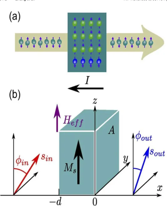
As shown in Fig.1(a), a spin polarized current carries some spins into and some spins out of an FM layer. The net number of spins, which is the difference between the majority and minority spins in the FM layer, is changed under an applied current. We are able to calculate the change in the total
037134-2 Zhang et al. AIP Advances 5, 037134 (2015)
FIG. 1. (a) A sketch of the spins localized in a FM layer replaced partially by the spins carried by a spin-polarized current flow. (b) Coordinates of the spin-polarized current flowing through an FM layer.
number of spins according to the conservation of spin angular momentum. Following this principle, we calculated the spin polarization of the FM layer and the threshold current for switching.
The coordinates we used here are shown in Fig. 1(b). Suppose that a normal current is spin-polarized after it has passed through the fixed FM layer and the direction of polarization is along si nat an angle φi nwith respect to the z axis. When it passes the free FM layer, the
polariza-tion will be changed to the direcpolariza-tion soutat an angle φoutwith respect to the z axis. The reason for
the change of polarization of the current is the exchange interaction between the spins carried by the current and localized in the free FM layer. Thus the spin polarization of the free FM layer is changed as well.
The MTJ structures we used were fabricated by Everspin. The multilayer structures include PtMn(20)/CoFe(2.27)/Ru(0.8)/CoFeB(2.2)/CoFe(0.525)/MgO(1.2)/CoFeB(2.5) (with units of nm).
The typical resistance decrease with a current is shown in Fig. 2(a). The red and blue dots are the experimental data of the APS and the PS resistances as a function of current, respec-tively. The resistance at parallel configuration RPS does not change as much as the resistance at
037134-3 Zhang et al. AIP Advances 5, 037134 (2015)
FIG. 2. (a) The resistances of the APS and PS in an MTJ decrease as a function of the current. (b) The TMR ratio η decreases as a function of the current. Solid lines are fitting curves using Eq. (5a).
anti-parallel configuration RAPSdoes when increasing the current. This is because the change of the
free FM layer polarization is related to the relative differences of the spin polarization between the spin-polarized current and that of the free FM layer itself. In the PS this difference is much smaller than in the APS. The TMR ratio η is defined as η= (RAPS− RPS)/RPS. η as a function of I is
plotted in Fig.2(b). We can see that the TMR ratio η decreases with increasing I as well.
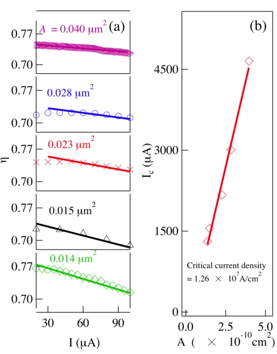
Next, we performed current dependent experiments on samples with various barrier cross sectional area A. In each measurement, the sample was placed in an external magnetic field directed along the easy axis of the sample. The magnetization configurations for the APS or the PS were achieved by setting the external magnetic field at -20 or 20 mT, respectively. In both APS and PS, a current with an amplitude from 0 to 100 µA was sent into the sample and at the same time, the resistance of the sample was detected by a multimeter. Thus, for a certain sample with cross sectional area A, the resistance current dependence at both APS and PS was measured. Then η for various currents was calculated. The η current dependence for samples with various A of 0.040, 0.028, 0.023, 0.015 and 0.014 µm2are plotted in Fig.3(a). η decreases with increasing current for
all measurements.
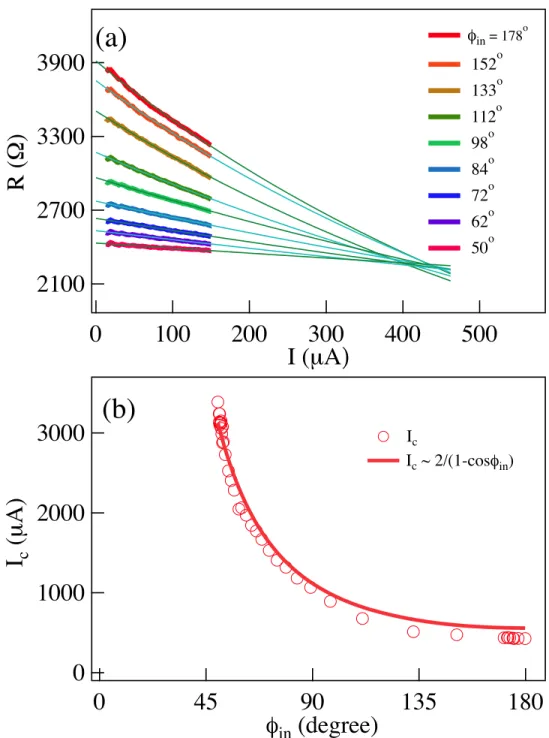
The angle φi n which describes the angle between the spin polarization of the current and the
magnetization of the layer the current is passing through is related to the magnetization of the fixed FM layer of the MTJ, which can be adjusted by an external field. From Jullière’s two current model,24we can calculate the angle between the magnetizations in the two FM layers as long as we know the resistance of the MTJ at each configuration. Then φi n at each configuration can be
calculated. The resistance of the MTJ, R, as a function of an applied current under various φi nwas
measured and is plotted in Fig.4(a). R decreases as a function of the current for various φi n. The
values of the angles φi n were 178, 152, 133, 112, 98, 72, 62 and 50◦ respectively, which were
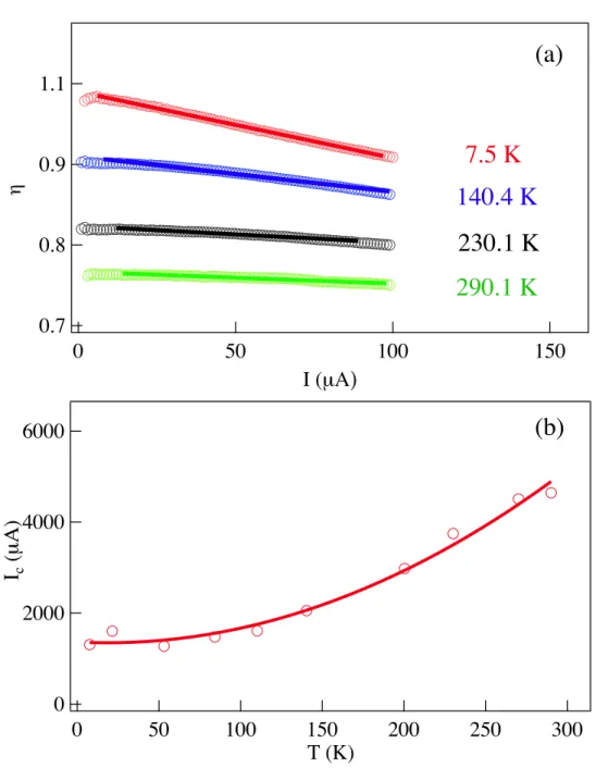
calculated by reading off the resistance at zero current and using Jullière’s two current model. Finally, we performed the temperature dependence experiments from 7.5 to 290.1 K. Fig.5(a)
shows η as a function of I at 7.5, 140.4, 230.1 and 290.1 K. A resistance decrease with increasing current was observed at various temperatures.
A well known way to explain the TMR current dependence has been established by several groups.25–29The basic idea is that a spin-transfer torque was introduced by a spin-polarized current
037134-4 Zhang et al. AIP Advances 5, 037134 (2015)
FIG. 3. (a) For different junction area A, all TMR ratios decrease as current I increases, which can be well fitted using Eq. (5a). (b) The critical current Icis proportional to A as shown by the solid line. The slope of this line indicates the threshold current density of 1.26 × 10⁷A/cm2for switching.
applied on the FM layer. Slonczewski showed that there was a close relationship between TMR and voltage-driven pseudo torque, and this torque is proportional to a well defined polarization factor, indicating that the TMR voltage-dependence is directly related to the spin-polarization of the FM layer.26Later, Slonczewski and Sun studied the voltage-driven torque in MgO based MTJ
and showed that the TMR greatly depends on extrinsic conditions including annealing, dislocations, added element at interfaces and sputtering conditions.27Heiliger and Stiles claimed that the torque
due to the current in an MTJ is interfacial. Also the de-phasing of the electrons is greatly reduced in typical MTJs because the current and spin current are carried by just a small fraction of the Fermi surface.28To avoid the complicated details concealed in the barrier and interfaces, we use a simple model to study the TMR current dependence by considering the conservation of angular momentum and particles. We just consider the beginning and the end points of the whole procedure, i.e. the
037134-5 Zhang et al. AIP Advances 5, 037134 (2015)
FIG. 4. (a) For different φi n, the resistance decreases as a function of current, and is well fitted by using Eq. (5b). All lines intersect around 2217 Ω at the current of 430 ± 20µ A. (b) Angle φi ndependence of Ic, which agrees well with Eq. (4) shown in the solid line.
moment the spin-polarized current arrives and the moment it is leaving. Then we can relate the spin polarization, the threshold current where TMR goes zero and the TMR ratio together. Furthermore, Slonczewski’s work also showed that the torque due to the current had a sin φ or a cos φ behavior, where φ is the angle made by the magnetization of the two FM layers.26,29We find a(1 − cos φ)−1
relation for the Icangle dependence, which is in agreement with the experimental data.
We consider the transport as shown in Fig.1again. The free FM layer has a cross sectional area A, a thickness d and a magnetization Msbefore any current is applied, as shown in Fig.1(b). Msis
037134-6 Zhang et al. AIP Advances 5, 037134 (2015)
FIG. 5. (a) η as a function of I at 7.5, 140.4, 230.1 and 290.1 K. (b) Icas a function of temperature T .
layer at a certain temperature Nf r eeis
Nf r ee= MsAd/µB (1)
where µB is Bohr magneton. When there is a spin polarized current with amplitude I passing
through the FM layer, within the spin relaxation time τr, I τr is the electric charge flowing through
the free layer. Because of the exchange interaction between the spins carried by the current and localized in the FM layer, the change of the number of majority spins Nr in the FM layer can be
calculated as
Nr(I) = −
Iτr
2e [Pi n(cos φi n− 1) − (cos φout− 1)Pout] . (2) Here, e= 1.6 ×10⁻¹⁹C, and P
i n and Poutare the polarization of the current before and after
037134-7 Zhang et al. AIP Advances 5, 037134 (2015)
is a function of the current I when there is a spin-polarized current passing through and can be calculated as Nf r ee(I) = Nf r ee− Nr(I). The spin polarization of the free FM layer Pf r ee, defined
as the ratio of the net spin to the number of electrons in the conduction band of the free FM layer, Nt ot al
f r ee, is a function of the current as well and can be written as Pf r ee(I) = Nf r ee(I)/N t ot al f r ee.
It is a good approximation to assume that the electrons flowing out the free layer have the same polarization and spin orientation as those in the free FM layer because the thickness of the free FM layer is larger than the spin relaxation length.30,31 Thus, φout= 0 and Pout= Pf r ee(I). Then the
polarization of the free layer can be written as,
Pf r ee(I) = Pf r ee(0)(1 − I/Ic). (3)
Here, we have made the substitutions τr= 1/αγHe f fand γ= 2µB/~, where α is the damping and γ
is the gyromagnetic ratio. Also, we assumed that Nf r eet ot al≫ Iτr/e and define Icas,
Ic≡ 2e ~ 2 1 − cos φi n α Pi n MsAdHe f f (4)
Combining Eq. (3) and Jullière’s two current model, the TMR ratio η and RAPS can be
represented as η = 2Pf i xPf r ee(1 − I/Ic) 1 − Pf i xPf r ee(1 − I/Ic) (5a) RAPS= RPS 1+ Pf i xPf r ee(1 − I/Ic) 1 − Pf i xPf r ee(1 − I/Ic) (5b) where Pf i xis the spin polarization of the fixed FM layer defined as the ratio between the number
of net spins and the total number of conduction electrons in the fixed FM layer. In Eq. (5a), the spin polarization of both FM layers Pf i xand Pf r eerefers to the original spin polarizations with no
applied current.
By fitting all the curves in Fig.3(a)using Eq. (5a), Icfor samples with various A is determined
and is plotted in Fig.3(b). The linear dependence of Icon A is as expected from Eq. (4). The linear
dependence also means that the threshold current density which can be calculated as Ic/A is all the
same for MTJs with various A. In our case, it is 1.26 × 10⁷A/cm2.
For the current dependence at various A, each curve in Fig.4(a)was fitted by using Eq. (5b). All fitting curves intersect near 430 ± 20 µA and the resistance at the intersection is 2217 Ω which is as the same as the PS resistance. Also, from the fitting, the Iccan be determined for various φi n. Ic
as a function of φi nis plotted in Fig.4(b), and the curve can be fit using Eq. (4) very well.
For the current dependence at various temperatures, the curves in Fig. 5(a) can be fit using Eq. (5a) as well. Since parameters such as Pi n, Msand He f fin Eq. (4) are related to T , determined
by the sample itself, the relationship between Ic and T is also sample dependent and may be
complicated. As showed in Fig.5(b), Icdoes not have a simple linear T dependence.
In conclusion, we performed TMR current dependence measurements on MTJs with various cross sectional area and under various temperatures. The threshold current Ic as a function of
the angle between the magnetization of two FM layers was studied as well, which showed a (1 − cos φi n)−1dependence. Our systematic data is useful for further study of the mechanism of the
current dependence in MTJ. To explain the current dependence of an MTJ, based upon spin angular momentum and particle conservation, a simple model was established. Experimental data of the resistance change due to a current is well explained and the Ic can be also determined from our
model.
We thank the helpful discussion with Y.S. Gui and M. Harder. This work was funded by NSERC, CFI, and URGP grants (C.-M.Hu). One of the authors (Z. H. Zhang) was supported by the China Scholarship Council (CSC).
1D. C. Ralph and M. D. Stiles,J. Magn. Magn. Mater.320, 1190 (2008).
2S. Kanai, Y. Nakatani, M. Yamanouchi, S. Ikeda, H. Sato, F. Matsukura, and H. Ohno,Appl. Phys. Lett.104, 212406 (2014). 3J. C. Slonczewski,J. Magn. Magn. Mater.159, L1 (1996).
037134-8 Zhang et al. AIP Advances 5, 037134 (2015)
5W. G. Wang and C. L. Chien,J. Phys. D. Appl. Phys.46, 074004 (2013).
6a. Manchon, R. Matsumoto, H. Jaffres, and J. Grollier,Phys. Rev. B86, 060404 (2012).
7S. Kanai, Y. Nakatani, M. Yamanouchi, S. Ikeda, H. Sato, F. Matsukura, and H. Ohno,Appl. Phys. Lett.104, 212406 (2014). 8J. Sun,Phys. Rev. B62, 570 (2000).
9G. Fuchs, J. Katine, S. Kiselev, D. Mauri, K. Wooley, D. Ralph, and R. Buhrman,Phys. Rev. Lett.96, 186603 (2006). 10S.-C. Oh, S.-Y. Park, A. Manchon, M. Chshiev, J.-H. Han, H.-W. Lee, J.-E. Lee, K.-T. Nam, Y. Jo, Y.-C. Kong, B. Dieny,
and K.-J. Lee,Nat. Phys.5, 898 (2009).
11V. S. Pribiag, I. N. Krivorotov, G. D. Fuchs, P. M. Braganca, O. Ozatay, J. C. Sankey, D. C. Ralph, and R. a. Buhrman,Nat. Phys.3, 498 (2007).
12A. Brataas, A. D. Kent, and H. Ohno,Nat. Mater.11, 372 (2012).
13S. Yuasa, A. Fukushima, T. Nagahama, K. Ando, and Y. Suzuki,Jpn. J. Appl. Phys., Part 243, L588 (2004). 14S. Yuasa, T. Nagahama, A. Fukushima, Y. Suzuki, and K. Ando,Nature Mater.3, 868 (2004).
15S. S. P. Parkin, C. Kaiser, A. Panchula, P. M. Rice, B. Hughes, M. Samant, and S. H. Yang,Nature Mater.3, 862 (2004). 16D. D. Djayaprawira, K. Tsunekawa, M. Nagai, H. Maehara, S. Yamagata, N. Watanabe, S. Yuasa, Y. Suzuki, and K. Ando,
Appl. Phys. Lett.86, 092502 (2005).
17S. Yuasa and D. D. Djayaprawira,J. Phys. D: Appl. Phys.40, R337 (2007).
18M. Hosomi, H. Yamagishi, T. Yamamoto, K. Bessho, Y. Higo, K. Yamane, H. Yamada, M. Shoji, H. Hachino, C. Fukumoto, H. Nagao, and H. Kano, Tech. Dig. IEEE Int. Electron Devices Meet. (2005), 459462.
19S. Ikeda, J. Hayakawa, Y. M. Lee, F. Matsukura, Y. Ohno, T. Hanyu, and H. Ohno,IEEE Trans. Electron Devices54, 991 (2007).
20S. Zhang, P. Levy, a. Marley, and S. Parkin,Phys. Rev. Lett.79, 3744 (1997).
21S. O. Valenzuela, D. J. Monsma, C. M. Marcus, V. Narayanamurti, and M. Tinkham,Phys. Rev. Lett.94, 1 (2005). 22J. Zhang and R. M. White,J. Appl. Phys.83, 6512 (1998).
23L. Yuan, S. Liou, and D. Wang,Phys. Rev. B73, 134403 (2006). 24M. Jullière,Phys. Lett.54, 225 (1975).
25J.Z. Sun and D.C. Ralph,J. Magn. Magn. Mater.320, 1227 (2008). 26J.C. Slonczewski,Phys. Rev. B - Condens. Matter Mater. Phys.71, 1 (2005). 27J.C. Slonczewski and J.Z. Sun,J. Magn. Magn. Mater.310, 169 (2007). 28C. Heiliger and M.D. Stiles,Phys. Rev. Lett.100, 1 (2008).
29J. Slonczewski, Phys. Rev. B 93, 7436 (1989).
30A. a. Kovalev, G. E. W. Bauer, and A. Brataas,Phys. Rev. B - Condens. Matter Mater. Phys.73, 1 (2006). 31T. Taniguchi, S. Yakata, H. Imamura, and Y. Ando,IEEE Trans. Magn.44, 2636 (2014).