Applied Surface Science
Volume 324, 1 January 2015, Pages 525–531
Studies of drag on the nanocomposite superhydrophobic surfaces
Jean-Denis Brassarda, b, D.K. Sarkarb, , , Jean Perrona
a Anti-icing Materials International Laboratory (AMIL), Université du Québec à
Chicoutimi, 555 Boulevard de l‘Université, Chicoutimi, Québec, Canada G7H 2B1
b Centre Universitaire de Recherche sur l’Aluminium (CURAL), Université du Québec à
Chicoutimi, 555 Boulevard de l‘Université, Chicoutimi, Québec, Canada G7H 2B1
Received 14 May 2014, Revised 15 October 2014, Accepted 15 October 2014, Available online 24 October 2014
doi:10.1016/j.apsusc.2014.10.084
Highlights
• The nanocomposite thin films of stearic acid (SA)-functionalized ZnO nanoparticles incorporated in epoxy polymer matrix have been achieved.
• SA-functionalization of ZnO nanoparticles in the thin films was confirmed by XRD and FTIR.
• The measured rms roughness of the thin film is found to be 12 ± 1 µm with the adhesion of 5B on glass.
• The wetting property shows that the surface of the film is superhydrophobic with the CA of 156 ± 4° and CAH of 4 ± 2°.
• The drag reduction on the surface of superhydrophobic glass sphere is 16% lower than as-received glass sphere.
Abstract
The nanocomposite thin films of stearic acid (SA)-functionalized ZnO nanoparticles incorporated in epoxy polymer matrix have been achieved. The X-ray diffraction (XRD) studies show the formation of zinc stearate on ZnO nanoparticles as the confirmation of SA-functionalization of ZnO nanoparticles in the thin films. Morphological analyses reveal the presence of micro-holes with the presence of irregular nanoparticles. The measured root mean square (rms) roughness of the thin film is found to be 12 ± 1 µm
with the adhesion of 5B on both glass and aluminum substrates. The wetting property shows that the surface of the film is superhydrophobic with the contact angle of water of 156 ± 4° having contact angle hysteresis (CAH) of 4 ± 2°. The average terminal velocity in the water of the as-received glass spheres and superhydrophobic spheres were found to be 0.66 ± 0.01 m/s and 0.72 ± 0.01 m/s respectively. Consequently, the calculated average coefficients of the surface drag of the as-received glass sphere and
superhydrophobic glass sphere were 2.30 ± 0.01 and 1.93 ± 0.03, respectively. Hence, the drag reduction on the surface of superhydrophobic glass sphere is found to be approximately 16% lower than as-received glass sphere.
Graphical abstract
Keywords : Functionalized nanoparticles; Nanocomposite thin film; X-ray diffraction; Superhydrophobicity; Drag reduction
1. Introduction
One the most studied phenomenon, at the present in the research in nanomaterials, is the wettability of the surfaces. The wetting phenomena can be categorized into four parts based on the contact angle of a water drop on a surface. The complete wetting signifies the contact angle on a surface is zero degree that refers as superhydrophilic. The contact angle below 90° is considered to be hydrophilic and the contact angle above 90° is considered to be hydrophobic. On the other hand, the surface said to be
superhydrophobic when the water contact angle is more than equal to 150°. The superhydrophobic surfaces are surfaces that easily repel water. The ability of repelling water is a well-known phenomenon that occurs frequently in nature. Several insects and plants possess this ability. Among them the most studied and well understood surface is
the lotus leaf, the symbol of purity, that has been analyzed through scanning electron microscope by Neinhuis and Barthlott in 1997 [1]. They observed that the surface of lotus leaf is not very smooth, as believed due to non-wetting properties, rather rough due to the co-existence of both micro and nano motifs. They also observed that these motifs are also covered with a low surface energy waxy material [1]. The micro–nano pattern on the surface allows large amount of air to be entrapped into the pattern while the low surface energy waxy coating inhibits the interaction with the water. These two
characteristics are the crucial parameters to obtain the superhydrophobic surfaces. Wenzel [2] as well as Cassie–Baxter [3] proposed two mathematical models to explain the wetting phenomena on rough surfaces that lead to superhydrophobic properties. In Wenzel model [2], the water drop penetrates the surface irregularities. Mathematically, Wenzel equation is written as
Equation (1) c o s θ′= Rw c o s θ
where the roughness factor Rw is the ratio of the true and apparent (geometric) surface areas. According to the Wenzel model, when the true contact angle θ of water on a
smooth surface is less than 90°, the apparent contact angle θ’ is less than the true
contact angle θ on a rough surface, and when the true contact angle θ is greater than
90°, the apparent contact angle θ’ is greater than the true contact angle θ on a rough
surface.
The Cassie–Baxter model [3] describes the effect of roughness on chemically
heterogeneous structures where the apparent contact angle is mathematically derived from the Cassie equation as follows:
Equation (2)
c o s θ′= f1 c o s θ1+ f
2 c o s θ2
where θ’ is the apparent contact angle of the composite coating consisting of two
components with contact angles θ1 and θ2 and corresponding area fractions f1 and f2. In
such a composite system f1 is assumed to be the solid surface and f2 is assumed to be air where θ2 is 180° and as f1 + f2 = 1, Eq. (2) can be written as
Equation (3) c o s θ′= f1( c o s θ
1+ 1 ) − 1
This equation explains that on a rough surface with large amount of air entrapment, in the surface irregularities, one can achieve a highly superhydrophobic surface with a very small area fraction f1 of the surface in contact with the water drop. The configuration leads to a very high contact angle and a very low contact angle hysteresis leading to the rolling-off of water drops on the contacting solid.
Accordingly to the Cassie–Baxter model, a water drop on a pattern surface, e.g. surface of a lotus leaf, will be in contact with a very little solid fraction and rest on the entrapped air into the pattern that effectively increase the water contact angle more than 150°. Each year, plenty of articles are published in the field of superhydrophobic surfaces. In general, various high surface energy materials like metals, oxides ceramics are used to obtain a surface with an optimum topography and further modified those surfaces with low surface energy polymers or organic molecules, to obtain superhydrophobic surfaces. Our group is actively working in this field and fabricated several superhydrophobic surfaces using fluorinated silica nanoparticles, methylated electromodified copper and aluminum surfaces and rf-sputtered Teflon coated etched aluminum surfaces [4], [5], [6], [7], [8], [9], [10] and [11].
The applications of the superhydrophobic surfaces are diverse. The main applications are the water repellency which is mainly used in the textile industries, the self-cleaning surfaces, now used on several building windows [4] and [5]. We have also shown that the superhydrophobic surfaces having the corrosion resistance properties as well as ice adhesion reduction properties [8] and [9]. Another important property of
superhydrophobic surfaces is the reduction of surface drag. The drag reduction has the potential application in the energy consumption of moving vehicles in our daily life. Drag is a frictional force that acts to the opposite to the motion of the moving fluids. The drag reduces the speed, and hence the efficiency of the moving cars, the aircrafts and even the boats [12]. The drag reduction is an emerging technology in automotive engineering. For reducing this effect, several geometries have been proposed to improve aerodynamic and hydrodynamic of the vehicles. The most recent development in this topic is related to the fabrication of nanostructured superhydrophobic surfaces [13]. Several authors proposed superhydrophobic coating methods that reduce drag and as much as evaluation methods for the drag reduction measurements over those
surfaces [14], [15], [16], [17] and [18]. The materials used to obtain the surfaces are varied, such as polymers [16], [17] and [19], sol–gel method [20] and [21] and nanostructured metals [22] and [23].
Apart from the water-drag on the superhydrophobic surfaces, studies of air-drag are also of interest to the automotive and aerospace industries. It has been shown that the air drag can be reduced by 4–5% by engineering the surface with riblet structure of 62 µm [24]. Similarly, Stenzel et al. proposed a paint based on aliphatic polyurethane resins that shows air-drag reduction of 6% [25]. A European patent shows an air-drag reduction of 10% with a composite coating, on a golf ball, consisting of silica particles in
polyurethane [26]. Also, a United States patent shows that a hydrophobic coating can reduce the air-drag with a composite coating of acrylic and of fumed silica, hydrophobic titania, and zinc oxide [27].
In this article, we describe the studies of surface drag of water on a superhydrophobic surface. The surface is a nanocomposite thin film of epoxy polymer containing stearic acid functionalized ZnO nanoparticles prepared by spray deposition.
2. The experimental
The ZnO nanoparticles having average diameter of 70 nm (purchased from MK Nano, Ontario, Canada) were functionalized with stearic acid (SA) organic molecules using 0.1 M ethanolic solution in an ultrasonic bath. The SA-functionalized ZnO nanoparticles were separated from ethanol by centrifuging process and further dried in an oven at 70 °C for more than 10 h. These functionalized ZnO nanoparticles were then dispersed into toluene utilizing an ultrasonic bath for 10 min. Furthermore, a commercial paint, based on an epoxy polymer (Bepoxy) has been added into the toluene solution that contains functionalized ZnO nanoparticles. This mixture of epoxy polymer and SA-functionalized ZnO nanoparticles has been sprayed on both flat glass surfaces as well as on surface of spheres (glass) to obtain superhydrophobic nanocomposite thin film. The prepared flat substrates were used for the surface characterization on the other hand the spherical objects were used for drag studies. Sprayed substrate thin films coatings have been characterized using X-ray diffraction (Bruker D8 Discover System), and Scanning electron microscope (SEM: JEOL JSM-6480 LV). The chemical
composition of surfaces was analyzed by infrared reflection absorption spectroscopy (IRRAS, Nicolet 6700FT-IR). The surface roughness of the films was measured using an optical profilometer (MicroXAM-100 HR 3D surface profilometer). The adhesion of the
nanocomposite thin films coating has been evaluated using ASTM D3359-02: Standard Test Methods for Measuring Adhesion by Tape Test. ASTM D3359-02 is a test method for assessing the adhesion of the coatings to metallic substrates by applying and
removing pressure sensitive tape over cuts made in the film. The adhesion of the films is evaluated by a rating from 0B where more than 65% of the coating is remove to 5B where 0% of the coating is removed, a perfect adhesion.
The wetting properties of the coating were performed by measuring both static and dynamic contact angles (Krüss contact angle goniometer) at five positions on each substrate using a 5 µL deionized water drop. The static contact angle has been abbreviated as CA and dynamic contact angle or contact angle hysteresis has been abbreviated as CAH throughout the text. The CAH is the difference between the advancing and the receding angle. The CAH measurements were made at room temperature following a very standard and commonly used experimental procedure as reported in the literature [10], [28] and [29]. In this method, a water drop of volume ∼5 µL was suspended with the needle and brought in contact with the superhydrophobic
surfaces using a computer controlled device as provided by Krüss GmbH. The contact CAH was measured by holding the water drop with a stationary needle in contact with the surface and moving the goniometer stage in one direction.
A water column of height 100 cm and diameter 22 cm was used for the studies of surface drag of a falling object. The falling objects were as-received and
superhydrophobic glass spheres of diameter ∼1.2 cm with an average weight of 5.5 g. The time of falling of each sphere in the water column at room temperature is recorded using a high speed camera (Motionblitz EoSens Cube7 Mikrotron GmbH) having the recording speed of 300 frames per second. Ten as-received as well as ten
superhydrophobic spheres were used to perform the drag test on hydrophilic (as water drop spread on it) and superhydrophobic surfaces.
The velocity used in this paper is the only vertical component. The terminal velocity (vT) is determined using following the equation:
where D is the distance traveled by the falling sphere. At speeds below 1 m/s, Reynolds number is Re < 3 × 10⁴. In this condition, the drag coefficient (CD) can be calculated as the inverse of the square of the velocity:
Equation (5)
3. Results and discussions
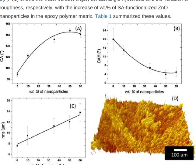
The superhydrophobic properties of the coatings have been optimized using different concentrations of SA-functionalized ZnO nanoparticles in the epoxy polymer matrix. Fig. 1(A)–(C) shows the water contact angle, contact angle hysteresis and the variation of roughness, respectively, with the increase of wt.% of SA-functionalized ZnO
nanoparticles in the epoxy polymer matrix. Table 1 summarized these values.
Fig. 1. (A) The water contact angle (CA), (B) the contact angle hysteresis (CAH), and (C) the surface roughness of the composite coatings (root mean square (rms)) of
the mass of ZnO. (D) 3D image of the optical profilometry of the surface having 50 wt.% SA-functionalized ZnO nanoparticles in the epoxy polymer.
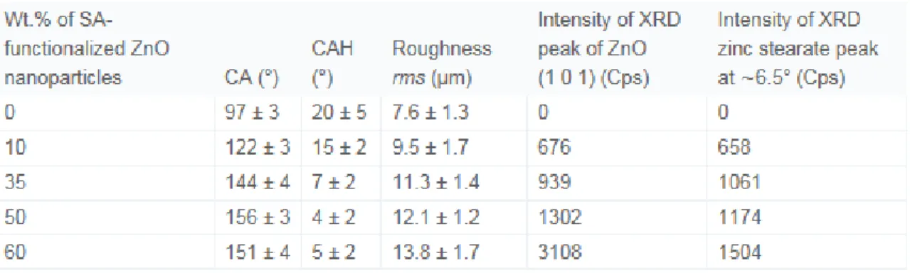
Table 1. Variation of contact angle (CA), contact angle hysteresis (CAH), roughness and XRD peak intensity of thin films prepared with varying SA-functionalized ZnO
nanoparticles in the epoxy polymer.
The roughness of the epoxy polymer coated surface is found to be 7.6 ± 1.3 µm, that has been increased to 9.5 ± 2.7 µm by incorporating 10 wt.% of SA-functionalized ZnO nanoparticles in the epoxy polymer matrix. It can be seen in Fig. 1(A), that the initial water contact angle on the epoxy polymer coated surface is found to be 97 ± 3°. The contact angle increased to 122 ± 3° on composite epoxy polymer coated thin film surface due to the addition of the 10 wt.% nanoparticles in the epoxy polymer matrix. The
roughness of the composite films further increased to 11.3 ± 1.4 µm and 12.1 ± 1.2 µm by incorporating 35 wt.% and 50 wt.% of nanoparticles, respectively. Consequently, the water contact angles are also increased, respectively, to 144 ± 4° and 156 ± 3°. It is clear that 50 wt.% nanoparticles incorporated composite epoxy polymer surface provides the highest water contact angle. It can be seen from Fig. 1(C) that the roughness
continued to increase and reached to a maximum value of 13.8 ± 1.7 µm at 60 wt.% of nanoparticles; however, Fig. 1(A) shows that the contact angle reduces to 151 ± 4°. It has been observed from Fig. 1(B) that the CAH reduces with the increase of the mass of SA-functionalized ZnO nanoparticles and become minimum at 50 wt.% with a value of 4 ± 2°.
With further increase of nanoparticles in the epoxy polymer, the coatings flake off due to very poor adhesion with the substrates. The adhesion test of the best coating has been shown in Fig. 4(G). It has been found that the composite coating prepared using 50 wt.% SA-funtionalized ZnO nanoparticles incorporated epoxy polymer matrix provided the
best coating adhesion which correlates best with the highest water contact angle with the optimum surface roughness value obtained on this surface. Our observation is in good agreement with the study of Karmouch et al. [30], where they found similar tendency on the roughness and the water contact angle on the composite epoxy polymer surfaces prepared with silica nanoparticles incorporated epoxy polymer.
Fig. 1(D) shows the 3D image of the optical profilometry of the nanocomposite thin films of SA-functionalized ZnO nanoparticles in the epoxy polymer. The obtained root mean square (rms) roughness of the thin film is found to be 12 ± 1 µm.
Fig. 2 shows the XRD pattern of the nanocomposite thin films of SA-functionalized ZnO nanoparticles in the epoxy polymer on a glass substrate with varying concentration of SA-functionalized ZnO nanoparticles. The diffraction peaks belong to the hexagonal ZnO (JCPDS # [01-089-1397]). The peak positions and their corresponding planes are
31.74°/ZnO (1 0 0), 34.38°/ZnO (0 0 2), 36.22°/ZnO (1 0 1), 47.48°/ZnO (1 0 2), and 56.54°/ZnO (1 1 0). It has been observed that the peak intensity of ZnO increases with the increase of mass of SA-functionalized ZnO nanoparticles in the epoxy polymer. Fig. 2(B) shows the low angles XRD pattern for 2θ ranges between 5° and 20°. The spectra
shows several peaks which belong to the zinc stearate (JCPDS # [00-055-1618]). It has also been observed that the peak intensity of zinc stearate also increases with the mass of SA-passivated ZnO nanoparticles in the epoxy polymer.
Fig. 2. X ray diffraction (XRD) pattern of the nanocomposite thin films of
SA-functionalized ZnO nanoparticles in the epoxy polymer on glass substrate as function of wt.% [(a) 0 wt.%, (b) 10 wt.%, (c) 35 wt.%, (d) 50 wt.%, and (e) 60 wt.%] of ZnO: (A) High angles XRD and (B) low angles XRD.
The XRD spectra at both low and high angles confirm that the thin films deposited on glass substrate has a zinc stearate covered ZnO nanoparticles (SA-functionalized ZnO nanoparticles). It also proves that the component of zinc stearate is not modified or altered when mixed to the epoxy polymer solution to obtain the composite thin films. Infrared reflection absorption spectroscopy (IRRAS) has been performed to understand the surface composition of the composite thin films. Fig. 3(A) shows the chemical structure of zinc stearate, a probable bonding between zinc oxide with stearic acid. Fig. 3(B) presents the IRRAS data of the nanocomposite thin films of SA-functionalized ZnO nanoparticles in the epoxy polymer on a glass substrate.
Fig. 3. (A) Chemical structure of zinc stearate-bonding between ZnO and stearic acid. (B) Infrared reflection absorption spectroscopy (IRRAS) spectrum of the nanocomposite thin films of SA-functionalized ZnO nanoparticles in the epoxy polymer on a glass substrate as function of wt.% of SA-passivated ZnO nanoparticles.
The IRRAS spectrum indicate clearly the presence of ZnO compound in the coating with a broad peak at 1400 cm−1[31]. The peaks at wavenumber range between 2800 and 2950 cm−1 belongs to the asymmetric, symmetric C–H stretching modes of –CH2 groups and asymmetric in-plane C–H stretching mode of the –CH3 group. Also the peak around 1500 cm−1 belongs to COOZn [31]. These results confirm that the surface of the
nanocomposites is composed of SA-functionalized ZnO nanoparticles, in other word zinc stearate, as well as host epoxy polymer.
Fig. 4 shows SEM images of the nanocomposite thin films of SA-functionalized ZnO nanoparticles with varying concentrations in the epoxy polymer on glass substrates. It is
seen from the low magnification images that the surface of the film is not very smooth rather contain several holes of irregular shapes and sizes. The depths of the holes are as high as 5 µm. However, the high magnification image, Fig. 4(F), demonstrates that the surface composed irregular embedded nanoparticles of an average size of ∼200 nm. This increase of size of the particles with respect to the initial size of the ZnO
nanoparticle is due to the presence of stearic acid and the epoxy polymer matrix around it. The SEM analysis helps to understand how the nanoparticles are covered with the paint to form a micro and a nano-structure.
Fig. 4. The low magnification of SEM images of the nanocomposite thin films of SA-functionalized ZnO nanoparticles in the epoxy polymer of (A) 0 wt.% of ZnO, (B) 10 wt.% of ZnO, (C) 35 wt.% of ZnO, (D) 50 wt.% of ZnO, and (E) 60 wt.% of ZnO. (F) High magnification of (D) 50 wt.% of ZnO. (G) Adhesion test of the coating AQ(D) having 50 wt.% of ZnO according to the ASTM D3359-02 standard and two 10 µL water drops colored with rhodamine B.
Fig. 4(G) shows the large scale superhydrophobic nanocomposite thin films of SA-functionalized ZnO nanoparticles in the epoxy polymer on glass substrate. The scratches on the surfaces are due to the ASTM D3359-02 standard to determine the adhesion of the thin films coatings on the surfaces. According to this standard the average adhesion is found to be 5B, a perfect adhesion. In addition, two 10 µL water drops colored with low concentration rhodamine B, show the low wettability of the coating.
Above results suggest that the optimized coating was obtained from the solution containing 50 wt.% SA-functionalized ZnO nanoparticles in the epoxy polymer. Hence, the same solution was used to coat the glass spheres for the water drag test. Fig. 5 shows the images taken from the high speed videos of the free-fall as-received glass spheres (Fig. 5(A)) and superhydrophobic thin film coated glass spheres (Fig. 5(B)) into the water column. At time, t = 0 s, just before the entrance in water both the spheres at the same height. However, Fig. 5(B) shows that the superhydrophobic thin film coated glass sphere advanced by 3.5 mm after 55 ms and 7.5 mm after 85 ms with respect to the as-received glass sphere. Fig. 5(B) also shows that the superhydrophobic film coated sphere is covered by a shell of an air plastron that effectively reduces the friction between the water and the substrates [15], [20] and [32]. The existence of the air-shell is supported by the Cassie–Baxter model. According to this model, the air entrapped in the holes of the rough surfaces, as mathematically presented in Eq. (3), enhances the water contact angle that leads to the superhydrophobic properties.
Fig. 5. The images from high speed camera videos of the free fall of (A) as-received glass sphere, and (B) and superhydrophobic thin film coated glass sphere in the water. The location of the spheres for both the cases are presented at time t = 0 s, 55 ms and 85 ms.
Fig. 6 presents the hydrodynamic results, the studies of drag, of the as-received glass spheres and superhydrophobic thin film coated glass spheres. Fig. 6(A) shows the terminal velocity measured on 10 as-received glass spheres as well as on 10
superhydrophobic thin films coated glass spheres. The terminal velocity of the falling as-received sphere in the water column varies between 0.64 m/s and 0.67 m/s. On the other hand, the terminal velocity of the falling superhydrophobic sphere was found to vary between 0.71 m/s and 0.73 m/s.
Fig. 6. Hydrodynamic results, studies of surface drag, of the as-received glass spheres and two superhydrophobic glass spheres. (A) The terminal velocities of 10 as-received glass sphere and 10 superhydrophobic glass spheres. (B) The average of the terminal velocities. (C) The coefficient of drag of 10 as-received glass sphere and 10
superhydrophobic glass spheres. (D) The coefficient of drag.
Fig. 6(B) shows that the average terminal velocity of the as-received glass spheres and superhydrophobic spheres were 0.66 ± 0.01 m/s and 0.72 ± 0.01 m/s, respectively. The coefficients of drag of the surfaces have been calculated using Eq. (5) from the
corresponding terminal velocities of the falling spheres and presented in Fig. 5(C). The average coefficients of the surface drag of the as-received glass sphere and
superhydrophobic glass sphere are 2.30 ± 0.01 and 1.93 ± 0.03. Fig. 5(D) demonstrates the values of surface drag of these two surfaces. The percentage of drag reduction on the superhydrophobic surface is found to be approximately 16%.
McHale et al. [32] have studied the surface drag of the falling objects in the water column. They prepared superhydrophobic spherical surfaces by spray coating of a commercial paint known as Hirec, on acrylic spherical beads. Their observed coefficient of drag varies between 5% and 15% depending on coatings and the size of the beads. We have observed a variation of 10–21% with an average coefficient of drag of 16%. Our results fit very well with their observations. However, depending on the methods to measure the coefficient of drag as well as the objects used, these values can be varied as found in the literature. Srinivasan et al. [17] observed a drag reduction of 2–7% on superhydrophobic surface prepared by spray coating method using
poly(methylmethacrylate). On the other hand, Daniello et al. [19] and [33] show a drag reduction of 15% on an oscillatory micro-roughen PTFE cylinder. Apart from the experimental observation of the drag reduction on the superhydrophobic surfaces, computer fluid dynamics (CFD) studies also have been previously performed, reporting promises to drag reduction to a greater extent. Rothstein [33] showed by CFD that the water drag can be reduced by 25% on a surface having microridges of 30 µm. Barbier et al. calculated a reduction of 20% water-drag on a superhydrophobic surface consisting of pyramidal structure [33] and [34].
4. Conclusion
Superhydrophobic surfaces were prepared using thin films of epoxy polymer
impregnated with stearic acid functionalized ZnO nanoparticles. The thin films were coated on flat objects of glass substrates for the characterization of morphological structural and wetting properties, on the other hand, on the spherical glass spheres for the studies of drag. The XRD analyses confirm the presence of stearic acid
functionalized ZnO nanoparticles in the thin films. Morphological analyses using both SEM and optical profilometry show the existence of micro-roughness having rms of 12 ± 1 µm. The wetting characterization shows that the thin film surface is
superhydrophobic with CA of 156 ± 4° and CAH of 4 ± 2°. The drag studies reveal that the coefficient of drag of the superhydrophobic thin films coated glass sphere is 16% lower than the as-received glass spheres.
Acknowledgementz
The authors would like to thank the Natural Sciences and Engineering Research Council of Canada (NSERC) and the Centre Québecois de recherche et de developpement de l’aluminium (CQRDA) for the financial support. We thank N. Saleema, NRC-Saguenay,
for IR studies. The authors would also thank Maxime Tremblay for his assistance while performing the drag studies.
References
[1] C. Neinhuis, W. Barthlott Ann. Bot., 79 (1997), pp. 667–677 [2] R.N. Wenzel
Ind. Eng. Chem., 28 (1936), pp. 988–994 [3] A.B.D. Cassie, S. Baxter
Trans. Faraday Soc., 40 (1944), pp. 546–551 [4] J.D. Brassard, D.K. Sarkar, J. Perron
ACS Appl. Mater. Interfaces, 3 (2011), pp. 3583–3588 [5] J.D. Brassard, D.K. Sarkar, J. Perron
Appl. Sci., 2 (2012), pp. 453–464 [6] Y. Huang, D.K. Sarkar, X.G. Chen Mater. Lett., 64 (2010), pp. 2722–2724 [7] Y. Huang, D.K. Sarkar, X.G. Chen Nano-Micro Lett., 3 (2011), pp. 160–165
[8] Y. Huang, D.K. Sarkar, D. Gallant, X.G. Chen Appl. Surf. Sci., 282 (2013), pp. 689–694
[9] D.K. Sarkar, M. Farzaneh
J. Adhes. Sci. Technol., 23 (2009), pp. 1215–1237 [10] D.K. Sarkar, M. Farzaneh, R.W. Paynter Mater. Lett., 62 (2008), pp. 1226–1229 [11] D.K. Sarkar, M. Farzaneh, R.W. Paynter Appl. Surf. Sci., 256 (2010), pp. 3698–3701 [12] R.B. Bird, E.N. Lightfoot, W.E. Stewart Transport Phenomena
(second ed.)J. Wiley, New York (2002) xii, 895 p.
[13] J.-D. Brassard, 1572, Université du Québec à Chicoutimi, 2011. [14] N.J. Shirtcliffe, G. McHale, M.I. Newton, Y. Zhang
ACS Appl. Mater. Interfaces, 1 (2009), pp. 1316–1323 [15] G. McHale, M.I. Newton, N.J. Shirtcliffe
[16] G.D. Bixler, B. Bhushan
Nanoscale, 5 (2013), pp. 7685–7710
[17] S. Srinivasan, W. Choi, K.-C. Park, S.S. Chhatre, R.E. Cohen, G.H. McKinley Soft Matter, 9 (2013), pp. 5691–5702
[18] H. Mertaniemi, V. Jokinen, L. Sainiemi, S. Franssila, A. Marmur, O. Ikkala, R.H. Ras Adv. Mater., 23 (2011), pp. 2911–2914
[19] R. Daniello, P. Muralidhar, N. Carron, M. Greene, J.P. Rothstein J. Fluid. Struct., 42 (2013), pp. 358–368
[20] S. Gogte, P. Vorobieff, R. Truesdell, A. Mammoli, F. van Swol, P. Shah, C.J. Brinker Phys. Fluids, 17 (2005), pp. 1–4
[21] K. Moaven, M. Rad, M. Taeibi-Rahni Exp. Therm. Fluid Sci., 51 (2013), pp. 239–243 [22] H. Dong, M. Cheng, Y. Zhang, H. Wei, F. Shi J. Mater. Chem. A, 1 (2013), pp. 5886–5891
[23] S. Lyu, D.C. Nguyen, D. Kim, W. Hwang, B. Yoon Appl. Surf. Sci., 286 (2013), pp. 206–211
[24] A. Sareen, R.W. Deters, S.P. Henry, M.S. Selig J. Sol. Energ. Eng., 136 (2014), p. 021007
[25] V. Stenzel, Y. Wilke, W. Hage Prog. Org. Coat., 70 (2011), pp. 224–229
[26] D. Fitchett, 10172697.4, European Patent Office, 2009.
[27] S. Kanagasabapathy, R.J. Baumgart, W.C. Su, F.E. Lockwood, 8,258,206, USPTO, 2012.
[28] M. Callies, Y. Chen, F. Marty, A. Pépin, D. Quéré Microelectron Eng., 78–79 (2005), pp. 100–105 [29] D. Quéré
Rep. Prog. Phys., 68 (2005), p. 2495 [30] R. Karmouch, G.G. Ross
Appl. Surf. Sci., 257 (2010), pp. 665–669 [31] A. Siddaramanna, N. Saleema, D.K. Sarkar Appl. Surf. Sci., 311 (2014), p. 182
[32] G. McHale, N.J. Shirtcliffe, C.R. Evans, M.I. Newton Appl. Phys. Lett., 94 (2009), pp. 0517011–0517014 [33] J.P. Rothstein
Ann. Rev. Fluid Mech., 42 (2010), pp. 89–109 [34] C. Barbier, E. Jenner, B. D‘Urso, arXiv (2014).