A partial hybrid stress solid-shell element for the analysis of laminated
composites
K. Raha, W. Van Paepegema, A.M. Habrakenb, J. Degriecka a
Dept. of Materials Science and Engineering, Ghent University, Technologiepark-Zwijnaarde 903, 9052 Zwijnaarde, Belgium bMécanique des Solides, des Fluides et des Structures, Université de Liège, chemin des Chevreuils 1, bât B52/3, 4000 Liège, Belgium
ABSTRACT
In this paper we introduce a low order partial hybrid stress solid-shell element based on the composite energy functional for the analysis of laminated composite structures. This solid-shell element has eight nodes with only displacement degrees of freedoms, and three-dimensional constitutive models can be directly employed in the present formulation without any additional treatment. The assumed interlam-inar stress field provides very accurate interlaminar stress calculation through the element thickness. These elements can be stacked on top of each other to model multilayer structures, fulfilling the interlaminar stress continuity at the interlayer surfaces and zero traction conditions on the top and bottom surfaces of the laminate. The present solid-shell does not show the transverse shear, trapezoidal and thickness locking phenomenon, and passes both the membrane and the bending patch tests. To assess the present formulation's accuracy, a variety of popular numerical benchmark examples related to element convergence, mesh distortion, shell and laminated composite analyses are
investigated and the results are compared with those available in the literature. The numerical results show the accuracy of the presented solid-shell element for the analysis of laminated composites.
Keywords : Partial hybrid stress ; Solid-shell element ; Composite energy functional ; Laminated composite
structures ; Interlaminar stress ; Multilayer structures
1. Introduction
Due to their high specific stiffness and strength, composite materials are becoming very popular in the last two decades in all engineering sectors, especially in aerospace, automotive and wind energy sectors. One of the advantages of composites is that the designer can tailor the material according to its stiffness and strength requirements in a specific direction. Despite their advantages, composite materials are also susceptible to intra-ply and/or inter-intra-ply damage, the latter being the most critical damage mode generally known as "delamination". Delaminations are caused by the interlaminar stresses (three transverse stresses) that arise due to the difference of material properties between the layers. Delaminations may significantly affect the structural integrity of the composite structure when they become sufficiently severe, and may finally lead to a catastrophic structural collapse. In order to predict the failure onset in composite structures, the interlaminar stress calculation is the most crucial and decisive step.
Many researchers attempted to find the interlaminar stresses for simple laminated structures using different methods, e.g. Finite Difference Method (FDM), displacement based Finite Element Method (FEM) and analytical methods. The pioneering work of Pagano and Pipes [43-45,54], where they determined the
interlaminar stress field in simple laminated beams and plates using the FDM, is still used as benchmark to check the accuracy of newly proposed FE formulations for the analysis of laminated composites. However, Pagano's solution method cannot be used to analyze complex laminated structures because it employs the FDM, and this method is generally restricted to handle simple geometries and boundaries. Wang and Choi [73] compared their analytical solution for the interlaminar stresses in laminates based on Eigen-functions with the results of Pipes and Pagano [54] and Wang and Crossman [74], based on FDM and FEM, respectively.
Because of the known limitations of analytical and FDM based analyses, which cannot be efficiently used for present day complex designs, a lot of research has been conducted in the last few decades to develop finite element based formulations for the determination of interlaminar stresses in laminates. However, the calculation of interlaminar stresses in laminates using finite element analysis is not an easy task, because the structure needs
to be modeled in great detail for the regions with high stress gradients, exhausting quickly the computational resources. For this reason a global-local finite element approach can be very useful, where the global response of the multilayer structure is combined with a detailed stress analysis in a particular region of interest [7]. The shell elements available in nowadays commercial codes are based on classical lamination theory (CLT), which even do not provide interlaminar stresses at all, rendering them only appropriate for the global structural analysis of laminates. The need of the development of an element that can be readily used in the local detailed stress analysis of laminates is becoming great.
The incompatibility between the overall dimensions of the composite structure (up to tens of meters) and the thickness of individual composite plies (typically 150-350 µm) makes solid-shell elements very attractive for the stress analysis of laminated structures. Solid-shell elements form a class of finite element models that are intermediate between thin shell and conventional solid elements. They can be referred to as finite element models that have shell kinematics assumption and possess no rotational degrees of freedoms (DOF). They have the same node and DOF configurations as that of conventional solid/brick elements, but they account for shell-like behavior in the thickness direction. Solid-shell elements perform well under high length-to-thickness aspect ratios, making them appropriate for the modeling of individual composite plies.
The enhanced assumed strain (EAS) method of Simo and Rifai [63] opened new opportunities for the researchers to tackle the locking pathologies in low-order brick elements for their use in the analysis of thin shell like structures. Wriggers and Reese [76] mentioned in their work that reliable 3D finite elements for shell-type structures with finite strains can be obtained using the EAS method of Simo and Rifai [63]. Significant works on the solid-shell elements include the intensive work of Schweizerhof and co-workers [19,23,25,26], Klinkel and Wagner [33], Klinkel et al. [32], Wagner et al. [72], Miehe [40], Vu-Quoc and Tan [70,71], to exploit the combination of the EAS method and the assumed natural strain (ANS) method to develop fully integrated low-order solid-shell formulations. Solid-shell formulations by Alves de Sousa et al. [2,3,5], Cardoso et al. [13], Legay and Combescure [36], Reese [58], Schwarze and Reese [61,62], Li et al. [37], employed the reduced integration schemes to enhance their accuracy and efficiency. Sze et al. [65,67,68] proposed many solid-shell formulations based on the hybrid stress formulation. In order to accurately model the displacement field in thin multilayer and sandwich structures, solid-shell formulations based on the layer-wise displacement theories are proposed by Moreira et al. [41] and Kulikov and Plotnikova [35].
However, the above mentioned solid-shell formulations are not capable of calculating the interlaminar stresses in composites accurately. This problem arises from the very fact that in displacement based formulations the displacements are the primary variables and stresses are derived from the displacements employing numerical differentiation at the Gauss points, thereby introducing numerical errors. Additionally, delaminations initiate at the interface between layers, therefore it is necessary to determine the interlaminar stresses at the interfaces rather than at the Gauss points, which is not possible in displacement based formulations. Furthermore,
application of the interlaminar stress continuity conditions at the interface surfaces and traction-free conditions at the top and bottom surfaces of the laminate in a displacement based formulation are not possible.
The above mentioned limitations of the displacement based formulations were obvious for the finite element developers since the beginning, therefore they started developing finite elements based on the complementary energy principle, where stresses are equilibrating within the element and the tractions are balancing along the interelement boundary. However these elements found limited use in general-purpose computer codes because they lack a judicious choice of basis functions. In 1964, a successful multifield finite element was proposed by Pian [47,69] exploiting the stationary condition of the complementary energy function, which was based on the assumed equilibrating stresses within the element and compatible displacements along the element boundary. Pian and Sumihara [46] developed later another version of this element based on the two field Hellinger-Reissner functional, which simplified the element stiffness matrix derivation. The prime motive behind the use of a multifield formulation is to directly approximate the stress field, the variable which usually is of primary interest for design purpose. Since 1964, numerous multifield finite elements have been presented and a large number of hybrid and mixed element formulations have been proposed [6,11,15,27,51,55].
The two field Hellinger-Reissner principle or its modified forms are the most popular energy principles to derive alternative element formulations for the analysis of composites. In the present formulation we employ the "composite energy functional", which is derived in the literature in different ways. For example Reissner [59,60] developed it using Lagrange multipliers and partial Legendre transformation method, Moriya [42] developed it using the Veubeke-Hu-Washizu variational principle [22,28,75] and Pian and Li [50] derived it employing the Hellinger-Reissner variational principle.
Similar to any other hybrid stress formulation, the selection of the optimal assumed stress modes for the present formulation is very important. In the present formulation we employ only the assumed interlaminar stress field in order to capture the interlaminar stresses accurately in the laminated composites. Similar to Hoa and Feng [27], eight partial stress modes have been utilized, which are statically condensed at the element level in order to obtain a purely displacement based global system of equations. The zero traction conditions at the top and bottom surfaces of the laminate and the interlaminar stress continuity at the interfaces between different laminate layers is directly enforced on the assumed partial stress field.
To relieve the transverse shear locking and curvature-thickness locking, the ANS method is employed. The ANS method was first applied on shells by Dvorkin and Bathe [20] to relieve transverse shear locking and by Betsch and Stein [9] to relieve the curvature-thickness locking. To circumvent the thickness locking problem, assumed transverse normal stress modes of zeroth order in the element normal direction are employed, as proposed by Pian [48]. As the present solid-shell is a low order element, no membrane locking is observed. As the present formulation focuses mainly on laminated composite structures, where material incompressibility is not an issue, the volumetric locking has not been treated. The present ANS based formulation shows no locking problems and passes both the membrane and the out-of-plane bending patch tests.
Limiting our focus to the structural analysis of laminated composites, which for most practical applications remain in the linear elastic range due to their relatively brittle nature, the present formulation is valid for geometrically linear analyses.
The outline of the paper is as follows. In section two the kinematic assumptions of the solid-shell element will be explained. In section three the variational setup, finite element discretization, multilayer solid-shell formulation and assumed partial stress field related issues will be presented. In section four the performance of the present element will be presented by investigating a variety of popular numerical benchmark examples from the literature. Finally, we conclude this paper.
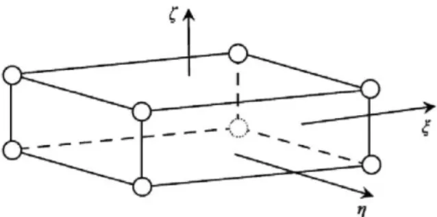
Fig. 1. Solid-shell element in isoparametric space.
2. Kinematic assumptions of solid-shell element
The terminology of solid-shell elements refers here to the FE models that are applicable to shell analyses and possess no rotational DOF. Solid-shell elements have the topology of conventional solid/brick elements, which provides the three-dimensional modeling of shell structures. Fig. 1 shows the solid-shell geometry represented in the isoparametric domain, where ξ, η and ζ are the natural coordinates [-1,+1].
For the present solid-shell element, the kinematic assumption of the shear deformable shells is applied.
According to this assumption the normal to the element mid-surface remains straight but not necessarily normal during the deformation. This assumption is fulfilled by a linear approximation of the in-plane displacements over the shell thickness [26]. Hence, any point in the reference configuration can be defined by the position vector (X) as follows:
where the subscripts 'T' and 'B' denote the projection of the variables on the top (ζ = +1) and bottom (ζ = -1) surfaces, respectively. It is to be noted that similar to shell elements, the kinematic description in Eq. (1) implicitly defines a preferred transverse direction of the element. This attribute differentiates the solid-shell element from a conventional solid/brick element, where there is no preferred thickness orientation. As mentioned previously, in the present formulation we restrict ourselves to only geometrically linear analyses. If needed, similar to other geometrically non-linear solid-shell formulations [2,3,8,10,12,26,40,57,70,71], the extension of the present element to geometrically non-linear formulation is a straightforward procedure.
3. Variational formulation and discretization
In this section, after discussing the composite energy functional [29], we shall perform the finite element discretization of the derived functional, leading to the stiffness matrix of a single layer solid-shell element. Afterwards, the multilayer solid-shell formulation, assumed stress formulation and related computational issues, and finally the ANS formulation will be discussed.
3.1. Composite energy functional
The well-known two-field Hellinger-Reissner functional, with displacements and stresses as the primary fields, is the starting point for the derivation of the composite energy functional (CEF). Satisfying the displacement boundary conditions a priori, the Hellinger-Reissner functional is given as follows:
where the displacement vector u and the second Piola-Kirchhoff stress tensor σ are the independent variables, and L denotes the symbolic strain-to-displacement differential operator. The vectors p* and t* are the prescribed body forces and traction vectors respectively. The vector û denotes the prescribed displacements on the
displacement boundary Sd.
The next step is to identify the stresses and strains, which are only continuous within each layer of a composite laminate (local variables), and those that are continuous across all the layers along the laminate thickness (global variables). Using the Voigt notation, the corresponding local and global partial stress and strain vectors can be identified as follows:
Now the local and global partial stress and strain vectors can be combined and defined as local and global field vectors respectively, which provides:
where the negative sign is introduced to ensure the symmetry of the combined constitutive relation, which gives:
where N is the combined constitutive matrix, given as follows:
where D1, D2 and D3 are the corresponding compliance sub-matrices of the material relating the stress and the strain fields.
Substitution of the global and local field vectors from (7) in the Hellinger-Reissner functional (2) and simplification leads directly to the CEF as follows:
There are two fields in the CEF, namely the displacement field u and the partial interlaminar stress field σG. The differential operator LL correlates the displacement field with the local partial strain vector. The constraint equations of the CEF are the constitutive Eq. (8), displacement boundary conditions (3) and the partial strain-displacement conditions as follows:
3.2. Finite element discretization
The starting point for the derivation of a finite element stiffness matrix is the discretization of independent variables and their variations in a given functional. After substitution of (7) in (11) the CEF reads as follows:
In each finite element domain the independent variables of the CEF (13) and their variations are interpolated as follows:
where the superscript h refers to the approximated values and δ depicts the variation of a given variable. The vectors qe and βe consist of the nodal displacements and the assumed transverse stress parameters of the element
respectively. To avoid the complex notation, the superscript e will not be used hereafter. The matrix N contains the shape functions of the element and the matrix P contains the assumed interlaminar stress parameters. Insertion of (14) and (16) in (13) leads to the following final discretized form of CEF:
The matrices Kd, H and G are the displacement based stiffness matrix, flexibility matrix and the leverage matrix of the finite element. The matrix PG contains the assumed interlaminar stress modes, whereby each column of the matrix PG represents an assumed stress mode. The matrices BL and BG are the well-known strain-displacement matrices for the locally and globally continuous strains (6) respectively, given as follows:
The three displacement components of node i are denoted by ui, νi and zi, where the subscript i for the present 8 node solid-shell element ranges from 1 to 8. For the displacement approximation in the element domain tri-linear shape functions Ni are employed, which in isoparametric space are given as:
where ξi, ηi and ζi are the isoparametric coordinates of the ith node. The CEF in (18) has two independent variables that are subject to variation. Considering the partial stationary condition of (18) with respect to β provides the relation between assumed stress parameters β and nodal displacements q as follows:
Similarly the partial stationary condition of (18) with respect to q and substitution of β from (25) leads finally to the governing equation of the element as follows:
where
The usual finite element assembly procedure can be employed to assemble further finite elements, resulting in the global system of equations for the complete structure.
3.3. Partial stress multilayer solid-shell element
The multilayer solid-shell elements consist of a stack of partial stress sub-elements. Therefore, the element formulated in the previous section can be stacked into a multilayer solid-shell element. Let the domain of the boundary value problem under discussion be D, which consists of a laminate with nl number of layers as shown in Fig. 2.
We divide the domain into nl number of non-overlapping finite elements in a manner that each composite layer is discretized using a single finite element. Similar to the previous section, this leads to the discretized form of the CEF as follows:
where the summation rule is employed to add the nl layers through the laminate thickness. All the terms with superscript i represent the corresponding variables in the ith layer of the laminate.
This leads to the assembling of nodal displacement vector, assumed stress vector and sub-element matrices through nl laminate layers as follows:
The displacement compatibility conditions and the continuity conditions on the interlaminar stresses need to be considered during the assembling process in (31). These assembled matrices can be directly plugged into (27) to determine the equivalent stiffness matrix of the multilayer solid-shell element. Having calculated the equivalent stiffness matrix of the multilayer solid-shell element, the usual displacement based finite element procedure can be followed to solve the system of algebraic equations in (26).
3.4. Assumed partial stress field
In the present formulation only the assumed interlaminar stress field has been employed. However, the
determination of the optimal stress polynomials for a mixed or hybrid formulation is not a straightforward task. If not enough polynomial terms are used in the assumed stress field, then there may exist zero energy modes leading to spurious kinematic deformations. On the other hand, if there are too many terms in the assumed stress polynomial, the element can behave over-rigid and more computational resources will be required.
There are many attempts in the literature to determine the optimal stress field [1,17,18,49,52,53,64,66], but the problem has been not solved completely. The eigenfunction method by Huang [29], the iso-function method by Han and Hoa [24] and the classification method by Feng et al. [21] provide a systematic basis to solve this problem.
According to the "necessary and sufficient condition" for partial hybrid stress elements [27], the number of stress modes in an assumed partial stress matrix (number of columns in matrix P) must be equal to or more than m (m =
n - r - nd), where n is the total element DOF, r the number of rigid body modes and nd is the order of the displacement based stiffness matrix. Here, first the rank of the displacement based stiffness matrix of a partial hybrid stress element is determined. Then using the iso-function method [24] a number of initial stress modes, composing the initial stress matrix Piso, are calculated. Finally these initial stress modes are classified to
representative stress modes employing the classification method [21], leading to the optimal partial stress matrix
Popt.
In the present formulation we employ the following optimal assumed stress matrix for a sub-element in a multilayer element, given in the natural coordinates of the element:
It is to be noted that the assumed transverse normal stress field in the assumed stress matrix P represents only the zeroth order field in ζ direction, which alleviates the thickness locking problem in an effective way. Hoa and Feng [27] also used the same assumed stress matrix as given in (32) to derive their hybrid solid element. The following transformation can be employed to transform the matrix P in (32) from isoparametric space to physical space:
where
and jik are the components of the Jacobian matrix evaluated at the element center as follows:
The hybrid finite element can also be formulated using the isoparametric coordinate system making the element less sensitive to mesh distortion [27].
3.5. Stress continuity and zero traction conditions
In this section we discuss the issue of zero traction and continuity conditions on the assumed interlaminar stresses. The assumed stress parameters βi in (31) are internal parameters, called layer stress parameters and are
different for each element. They are not independent and the assembly of the flexibility and leverage matrices given in (31) for nl number of layers cannot be performed based on these layer stress parameters. One needs to transform these layer stress parameters to so-called surface stress parameters in order to apply the zero traction and continuity conditions on the assumed stresses. If the surface stress parameters are used directly in the assumed partial stress field, the transformation will not be necessary [27]. This gives the interlaminar stress field in the following form:
where λTi and λBi are the surface stress parameters corresponding to the upper and lower surfaces of the ith element, respectively.
Now the interlaminar stress continuity at the interfaces of two adjacent layers i and i + 1 can be expressed as follows:
Therefore, one obtains the necessary condition for P as follows:
Having derived the surface stress parameters (36), the application of the interlaminar stress continuity condition at the interfaces between different layers of the laminate is a straightforward task. The traction free conditions on the interlaminar shear stresses on the top and bottom surfaces of the laminate are enforced in the following way:
where the superscript 1 and nl depicts the first and the last element through the laminate thickness.
Fig. 3. Sampling points shown on solid-shell element for ANS interpolation.
3.6. Assumed natural strain formulation
The ANS method has become an essential tool of numerous shell and solid-shell formulations to tackle the transverse shear locking problem, which owes to its simplicity and efficiency. In the beginning, the ANS method was derived purely from the engineering intuition, as proposed by Hughes and Tezduyar [30] for plate elements and later by Dvorkin and Bathe [20] for shell elements. Later, Betsch and Stein [9] exploited this method to relieve the curvature-thickness locking in shells.
The core idea behind this method is to redefine the interpolation functions for those strain components, which are plagued by locking phenomena. This is achieved by interpolating the plagued strain components referring to the points in the element domain, where the parasitic influences become zero. These points are referred to as sampling or tying points as depicted in Fig. 3. In the present work we use the ANS method on the transverse strain components to relieve the transverse shear locking effects, as originally proposed by Dvorkin and Bathe [20].
The four sampling points A, B, C and D are located at the four mid-points of the element edges at ζ = 0, as shown in Fig. 3. The following interpolation functions defined in isoparametric coordinates are applied on the compatible transverse shear strains:
where γξζA, γξζB, γηζC and γηζD are the transverse shear strains at sampling points A, B, C and D, respectively,
defined in isoparametric coordinates.
Similarly we apply ANS interpolation on the transverse normal strain to relieve the curvature-thickness locking, as proposed by Betsch and Stein [9]. As shown in Fig. 3, the four sampling points E, F, G and H are located at the four corners of the element middle surface. The following linear interpolation function defined in
Table 1 Comparison of nodal displacement results in membrane patch test.
Node number Exact Present element
u v u v
1 5.000 × 10⁻⁵ 4.000 × 10⁻⁵ 5.000 × 10⁻⁵ 4.000 × 10⁻⁵
2 1.950 × 10⁻⁴ 1.200 × 10⁻⁴ 1.950 × 10⁻⁴ 1.200 × 10⁻⁴
3 2.000 × 10⁻⁴ 1.600 × 10⁻⁴ 2.000 × 10⁻⁴ 1.600 × 10⁻⁴
4 1.200 × 10⁻⁴ 1.200 × 10⁻⁴ 1.200 × 10⁻⁴ 1.200 × 10⁻⁴
Table 2 Bending patch test - comparison of nodal displacement results.
Node number Exact Present element
u v w u v w
1 2.500 × 10⁻⁸ 2.000 × 10⁻⁸ 1.400 × 10⁻⁶ 2.500 × 10⁻⁸ 2.000 × 10⁻⁸ 1.400 × 10⁻⁶
2 9.750 × 10⁻⁸ 6.000 × 10⁻⁸ 1.935 × 10⁻⁵ 9.750 × 10⁻⁸ 6.000 × 10⁻⁸ 1.935 × 10⁻⁵
3 1.000 × 10⁻⁷ 8.000 × 10⁻⁸ 2.240 × 10⁻⁵ 1.000 × 10⁻⁷ 8.000 × 10⁻⁸ 2.240 × 10⁻⁵
4 6.000 × 10⁻⁸ 6.000 × 10⁻⁸ 9.600 × 10⁻⁶ 6.000 × 10⁻⁸ 6.000 × 10⁻⁸ 9.600 × 10⁻⁶
Table 3 Bending patch test - comparison of Bending patch test - comparison of different element formulations.
Element Present Hauptmann and
Schweizerhof [26] Betsch et al. [8] Miehe [40] Klinkel et al. [32] Vu-Quoc and Tan [70]
Hoa and Feng [27]
Does element pass the test?
Yes No No No No Yes No
Fig. 4. The five element membrane patch test: geometric dimensions (x:y:z = 0.24:0.12:0.001).
4. Numerical examples
In this section we assess the performance of the proposed formulation for a number of shell/solid-shell benchmark problems available in the literature. In this regard, we particularly focus on the element patch tests and convergence behavior, results sensitivity to mesh distortion and element aspect ratios, known locking issues and structural analysis of shells and multilayer thick and thin composites. The present element will also be compared with other well-known hybrid stress based solid elements available in the literature to show its suitability for the analysis of very thin shell-like structures. The numerical results will be compared with the reference results (analytical or numerical) available in the literature. A full numerical integration scheme has been employed in the following numerical examples.
4.1. Membrane patch test
This test was originally proposed by MacNeal and Harder [39] and originally aimed to check the membrane behavior of plate and shell elements. In order to adapt to the 3D topology of solid-shell elements, the number of nodes has been doubled as shown in Fig. 4. The material parameters for the plate are taken as: E = 106 and v = 0.25.
The following displacements u, v and w along the x, y and z axes respectively are imposed on the boundary nodes of the plate:
The theoretical solution of the constant in-plane stress field in all the elements is given as:
Table 1 shows the excellent agreement between the displacements of internal nodes calculated using the present element and the exact solution. The stresses calculated using the present element also agree with (43). Therefore the present element passes the membrane patch test successfully.
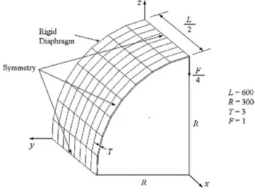
Fig. 7. Pinched cylinder with end diaphragms: material properties (E = 3 × 10⁶, v = 0.3).
Table 4 Normalized central transverse deflection for the clamped square plate (v = 0.3).
L/T Mesh Kirchhoff Present RESS HCiS12 S4E6P7 MITC4 CYSE PHSS
100 2 × 2 1.000 0.867 0.893 0.869 0.869 0.868 0.884 0.718 4 × 4 1.000 0.968 0.978 0.970 0.971 0.969 0.975 0.794 1000 2 × 2 1000 0.866 0.886 0.866 0.866 0.814 0.828 0.716 4 × 4 1000 0.966 0.975 0.966 0.966 0.966 0.971 0.791 4000 2 × 2 64,000 0.866 - - - - - 0.716 4 × 4 64,000 0.967 - - - - - 0.790
Table 5 Change of the normalized central deflection with increasing distortion parameter Δ (2 × 2 mesh, L = 100, S =100). Δ 0 2.5 5 7.5 10 12.5 Present 0.867 0.863 0.853 0.834 0.810 0.767 RESS 0.893 0.888 0.871 0.846 0.814 0.777 HCiS12 0.869 0.825 0.771 0.712 0.665 0.606 CYSE 0.884 0.879 0.862 0.830 0.780 0.703 MITC4 0.867 0.863 0.847 0.816 0.760 0.681 S4E6P7 0.869 0.827 0.774 0.717 0.663 0.616 QS/E9 0.073 0.066 - - - - QS/E12 0.874 0.514 - - - - PHSS 0.718 0.672 0.576 0.474 0.379 0.286
4.2. Bending patch test
This test was also suggested by MacNeal and Harder [39] and originally aimed to check the out-of-plane bending behavior of plate and shell elements. In order to pass this test, a shell/solid-shell element must be free from the thickness and transverse shear locking pathologies. Same geometry, discretization and material parameters are employed as in the membrane patch test. The following displacements are imposed on the boundary nodes to construct a constant bending stress state in the out-of-plane bending load:
The numerical results of the displacements of the internal nodes agree well with the exact solution as shown in Table 2. The computed stresses are also in perfect agreement with (45). Therefore the present element passes the out-of-plane bending patch test successfully.
Different displacement based solid-shell formulations in the literature, e.g. by Hauptmann and Schweizerhof [26], Betsch et al. [8], Miehe [40], Klinkel et al. [32], Vu-Quoc and Tan [70], and the partial hybrid stress solid formulation by Hoa and Feng [27], are checked for the out-of-plane bending patch test in Table 3. It can be seen that most of the element formulations do not pass this patch test, while the present formulation and the
displacement based solid-shell formulation by Vu-Quoc and Tan [70] pass this test. However, contrary to the present formulation, the solid-shell formulation by Vu-Quoc and Tan [70] cannot provide the accurate interlaminar shear stress field in laminated composites.
Table 6 Normalized transverse central deflection for pinched cylinder with end diaphragms.
Mesh Present RESS HCiS12 H1/ME9 S4E6P7 MITC4 PHSS
4 × 4 0.426 0.112 0.104 0.104 0.392 0.370 0.042
8 × 8 0.787 0.590 0.494 0.494 0.746 0.728 0.079
16 × 16 0.973 0.933 0.912 0.912 0.923 0.930 0.165
32 × 32 0.991 0.998 0.995 0.995 0.982 0.971 0.334
Table 7 Comparison of maximum transverse central deflection.
S = L/H Interface no. Korelc [34] Present CLT
4 4 3.023 3.019 0.510 3 2.925 2.920 0.510 2 2.864 2.857 0.510 1 2.839 2.831 0.510 10 4 0.934 0.933 0.510 3 0.933 0.932 0.510 2 0.931 0.929 0.510 1 0.929 0.928 0.510 50 4 0.527 0.527 0.510 3 0.527 0.527 0.510 2 0.527 0.527 0.510 1 0.527 0.527 0.510
Fig. 9. The cross-section of a laminated [0°/90°/0°] beam subjected to sinusoidal transverse loading.
Fig. 10. Finite element mesh for the half of the beam model (S = 4).
4.3. Clamped square plate with concentrated load
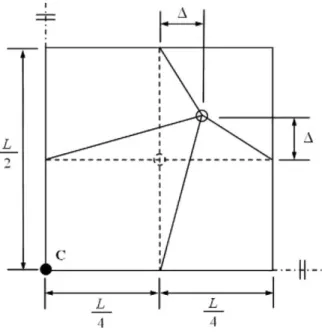
In this example we examine the present solid-shell formulation under several critical conditions, i.e. very high aspect ratio and mesh distortion and locking issues. A square plate of L × L in-plane dimensions and T thickness is subjected to a concentrated load and clamped at all four sides as shown in Fig. 5. Two meshes (2 × 2 and 4 × 4) are investigated to model one quadrant of the plate exploiting symmetry.
In order to check the locking behavior of the present formulation under high length-to-thickness aspect ratios (S = L/T), we investigate the transverse central deflection of the plate for different aspect ratios and meshes. To check the element accuracy for mesh distortion effects, we employ a distortion parameter Δ (Fig. 6) to the central node of the 2 × 2 mesh and S = 100.
The numerical results are normalized using the Kirchhoff plate solution and compared with the RESS and HCiS12 elements from Alves de Sousa [2-4], S4E6P7 element from César de Sá et al. [16], MITC4 element from Dvorkin and Bathe [20], CYSE element from Cardoso et al. [14] and QS (N)/E9, QS/E12 elements from Korelc [34] and the partial-hybrid stress solid element (PHSS) by Hoa and Feng [27]. In Table 4 the performance of the present formulation is investigated for v = 0.3 with different element aspect ratios and compared with the previously mentioned references. It can be seen from the Table 4 that the element performance for a wide range of aspect ratios is excellent without any transverse shear locking. The present element shows very good behavior even for extremely thin plate configuration (S = 4000), making it suitable for the thin multilayer structural analysis. On the other hand, the partial hybrid solid element by Hoa and Feng [27] is plagued by the element locking phenomena and behaves relatively stiff, and converges very slowly.
The influence of the mesh distortion on the numerical results is summarized in Table 5. In this study we use 2 × 2 mesh, L = 100 and S = 100. It can be seen from this comparison that the element shows insensitivity to different levels of mesh distortion. Even for very extreme mesh distortion (∆ = 12.5) the results of the present element are reasonable, while the results of the partial hybrid solid element by Hoa and Feng [27] degrade significantly with increasing mesh distortion.
Fig. 11. Comparison of transverse shear stress (x = 0) distribution through-the-thickness for S = 4.
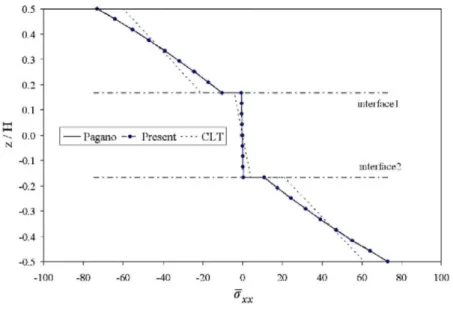
Fig. 12. Comparison of in-plane normal stress (x = L/2) distribution through-the-thickness for S = 4.
4.4. Pinched cylinder with end diaphragms
This example is an established benchmark for shell formulations to demonstrate their ability to analyze shell structures. In this example a pair of unit concentrated loads F is applied on a cylindrical shell structure having rigid diaphragms at the ends with the radius R, length L and thickness T, as depicted in Fig. 7. The cylinder is composed of isotropic material, where the material and geometrical parameters are also given in Fig. 7. The transverse deflection at the load application point is normalized using the analytical solution (wanalytical = 1.82488 × 10⁻⁵) and compared with the RESS and HCiS12 elements from Alves de Sousa [2-4], H1/ME9 element from Kasper and Taylor [31], S4E6P7 element from César de Sa et al. [16], MITC4 element from Dvorkin and Bathe [20] and the partial-hybrid stress solid element (PHSS) by Hoa and Feng [27] in Table 6. It is evident from Table 6 that the present formulation approaches the analytical solution rapidly with a moderately fine mesh. The convergence behavior of the investigated element formulations is depicted in Fig. 8. In
comparison to other element formulations in the literature, the present formulation shows superior convergence behavior, approaching the reference solution in a quadratic manner. This proves the accuracy of the present
solid-shell formulation for the structural analysis of thin shell structures.
Fig. 13. Comparison of transverse shear stress (x = 0) distribution through-the-thickness for S = 10.
Fig. 14. Comparison of in-plane normal stress (x = L/2) distribution through-the-thickness for S = 10.
Fig. 16. Finite element mesh for one quadrant of the laminated plate model (S = 4).
Table 8 Comparison of normalized stresses and transverse deflection in the square laminate plate (B = A).
s Source (A/2, B/2, ±H/2) (A/2, B/2, ±H/6) (0, B/2, 0) (A/2, 0, 0) (A/2,B/2,0)
4 Pagano [44] 0.801 0.534 0.256 0.217 - -0.755 -0.556 Hybrid [38] 0.717 0.517 0.263 0.221 2.020 -0.679 -0.541 Reddy [56] 0.7346 0.1832 1.9218 Present 0.805 0.537 0.260 0.216 2.041 -0.760 -0.561 10 Pagano [44] 0.590 0.285 0.357 0.123 -0.590 -0.288 Hybrid [38] 0.580 0.285 0.367 0.127 0.755 -0.580 -0.289 Reddy [56] 0.568 0.103 0.713 Present 0.590 0.284 0.358 0.128 0.759 -0.589 -0.286 20 Pagano [44] ±0.552 ±0.210 0.385 0.094 - Hybrid [38] ±0.553 ±0.210 0.395 0.099 0.517 Present ±0.551 ±0.210 0.385 0.096 0.517 CLT ±0.539 ±0.180 0.395 0.0823
4.5. Bending of a multilayer composite beam
In this example we analyze a three-layer laminated beam with fiber orientation [0°/90°/0°] to investigate the accuracy of the present element to calculate the interlaminar stresses in multilayer structures. The beam is supposed to be infinitely long in the y-direction and simply supported along the two edges as shown in Fig. 9. The beam is subjected to a transverse sinusoidal loading on the top surface as follows:
Each lamina of the laminated beam is idealized as a homogenous transversely isotropic material with following material properties in the principal material coordinate system:
Three different beam geometries are considered, i.e. a thick beam with low length to height ratio (S = L/H = 4), moderately thin beam (S = L/H = 10) and very thin beam (S = L/H = 50). Only one half of the beam is analyzed for all configurations exploiting the symmetry. The half of the beam is discretized using ten elements in the x-direction, one element in the y-direction and 12 elements in the z-direction as shown in Fig. 10. This way, we discretize each laminate layer using four solid-shell elements.
The numerical results are normalized as follows:
The maximum central transverse deflection is compared with Pagano's elasticity solution [43] and CLT in Table 7, where the surface number indicates the location of each interface of the laminate (Fig. 9). The
maximum central deflection given by the present element is in good agreement with Pagano's elasticity solution [43] from thick to thin beam configurations.
The transverse shear stress (x = 0) distribution and in-plane normal stress (x = L/2) distribution through the laminate thickness are shown in Figs. 11 and 12, respectively, for the thick beam configuration (S = 4). The CLT and elasticity results of Pagano [43] are also shown in the same figures. It can be seen from these Figures that there is excellent agreement between Pagano's results and the present element results. As expected, the CLT is not able to capture the through-the-thickness effects in a thick laminate structure.
For the thin beam configuration (S = 10) the transverse shear stress (x = 0) distribution and in-plane normal stress (x = L/2) distribution is shown in Figs. 13 and 14 respectively. The present formulation's results are again in excellent agreement with Pagano's elasticity results. It is to be noted that the CLT results for thin beam configuration are reasonably accurate.
Table 9 Comparison of normalized stresses and transverse deflection in the rectangular laminate plate (B = 3A). s Source (A/2, B/2, ±H/2) (A/2, B/2, ±H/6) (0, B/2, 0) (A/2, 0, 0) (A/2, B/2, 0)
4 Pagano [44] 1.140 0.109 0.351 0.033 2.820 -1.100 -0.119 Hybrid [38] 1.717 0.108 0.360 0.033 2.828 -0.975 -0.118 Reddy [56] 1.036 0.103 0.272 0.035 2.641 Present 1.133 0.106 0.350 0.0325 2.822 -1.08 -0.121 10 Pagano [44] 0.726 0.042 0.420 0.015 0.919 -0.725 -0.044 Hybrid [38] 0.709 0.043 0.428 0.015 0.921 -0.707 -0.045 Reddy [56] 0.692 0.039 0.286 0.017 0.862 Present 0.719 0.0411 0.416 0.0151 0.917 -0.717 -0.0435 20 Pagano [44] 0.650 0.029 0.434 0.012 0.610 -0.650 -0.030 Hybrid [38] 0.653 0.030 0.450 0.012 0.611 -0.646 -0.030 Reddy [56] 0.641 0.029 0.289 0.014 0.594 Present 0.647 0.0292 0.432 0.0118 0.607 -0.647 -0.0298 CLT ±0.623 ±0.025 0.440 0.011 0.503
4.6. Bending of rectangular laminated plates
In this problem we demonstrate the accuracy of the present solid-shell element to calculate the interlaminar stress field in a simply supported rectangular laminated plate subjected to bending loading for thick (S = A/H = 4), moderately thin (S = A/H = 10) and thin (S = A/H = 20) configurations. The in-plane dimensions of the laminated plate are A × B and thickness H with three layers [0°/ 90°/0°] of equal thickness, as depicted in Fig. 15. The following two plate geometries are investigated: (i) square plate (B = A) and (ii) rectangular plate (B = 3A). Each layer of the plate is idealized as homogenous transversely isotropic material with the material properties given in (47). Due to the symmetry, only one quadrant of the plate (0 < x < A/ 2, 0 < y B/2, 0 < z < H) is discretized using a 4 × 4 mesh as shown in Fig. 16. Each laminate layer is discretized using four solid-shell elements, resulting to 12 solid-shell elements in the thickness direction of the plate (Fig. 16).
The following distributed transverse load is applied on the top surface of plate:
The numerical results are normalized as follows:
This problem has also been investigated by Pagano [44] using the elasticity theory, by Reddy [56] using higher order shear deformation theory and by Liou and Sun [38] using the hybrid finite element method. The results of the present formulation are compared with previously mentioned references for square (B = A) and rectangular (B = 3A) plate geometries in Tables 8 and 9, respectively, for thick, moderately thin and thin plate
configurations. These results show that the present formulation provides excellent interlaminar stress resolution for a wide range of laminated plate geometries and configurations. As expected, the CLT results provide
reasonable results only for the thin plate configuration (S = 20). For the thick plate configuration, CLT results are incorrect.
5. Closing remarks
In the present paper we presented a partial hybrid stress solid-shell element that provides accurate interlaminar stress results for laminated composites. The present solid-shell formulation shows a clear advantage over its displacement based counterparts, because of its ability to calculate the interlaminar stress field accurately, fulfilling the necessary traction continuity condition at layer interfaces and zero transverse shear stress conditions on the top and bottom surfaces in a laminate.
The presented element has been subjected to a variety of numerical benchmark problems, and the results of this numerical study confirm the good convergence and locking free behavior of the present formulation. The element passes both the membrane and out-of-plane bending tests and shows insensitivity towards mesh distortion. The element is suitable for the structural analysis of thin shells and provides accurate results even at high element aspect ratios. The composite benchmark problems show the element's ability to accurately calculate the through-the-thickness stress field from thin to thick multilayer structures.
Acknowledgements
The authors would like to acknowledge the support of the Fund for Scientific Research - Flanders (FWO-Vlaanderen) and the Interuniversity Attraction Poles Program phase 6 (IUAP) of the Federal Science Policy of Belgium and the partners of IUAP-VI (www.m3phys.be).
References
[1] S. Ahmad, B.M. Irons, An assumed stress approach to refined isoparametric finite elements in three dimensions, Finite Elem. Methods Engrg. 85 (1974) 85-100.
[2] R.J. Alves de Sousa, R.P.R Cardoso, R.A.F. Valente, J.W. Yoon, J.J. Gracio, R.M.N. Jorge, A new one-point quadrature enhanced assumed strain (EAS) solid-shell element with multiple integration points along thickness: Part I - geometrically linear applications, Int. J. Numer. Methods Engrg. 62 (2005) 952-977.
[3] R.J. Alves de Sousa, R.P.R. Cardoso, R.A.F. Valente, J.W. Yoon, J.J. Gracio, R.M.N. Jorge, A new one-point quadrature enhanced assumed strain (EAS) solid-shell element with multiple integration points along thickness: Part II: Nonlinear applications, Int. J. Numer. Methods Engrg. 67 (2006) 160-188.
[4] R.J. Alves de Sousa, R.M.N. Jorge, R.A.F. Valente, J.M.A.C. de Sa, A new volumetric and shear locking-free 3D enhanced strain element, Engrg. Comput. 20 (2003) 896-925.
[5] R.J. Alves de Sousa, J.W. Yoon, R.P.R. Cardoso, R.A. Fontes Valente, J.J. Grâcio, On the use of a reduced enhanced solid-shell (RESS) element for sheet forming simulations, Int. J. Plast. 23 (2007) 490-515.
[6] S.N. Atluri, RH. Gallagher, O.C. Zienkiewicz, Hybrid and Mixed Finite Element Models, John Wiley, 1983.
[7] T. Belytschko, J. Fish, A. Bayliss, The spectral overlay on finite-elements for problems with high gradients, Comput. Methods Appl. Mech. Engrg. 81 (1990) 71-89.
[8] P. Betsch, F. Gruttmann, E. Stein, A 4-node finite shell element for the implementation of general hyperelastic 3D-elasticity at finite strains, Comput. Methods Appl. Mech. Engrg. 130 (1996) 57-79.
[9] P. Betsch, E. Stein, An assumed strain approach avoiding artificial thickness straining for a nonlinear 4-node shell element, Commun. Numer. Methods Engrg. 11 (1995) 899-909.
[10] M. Bischoff, E. Ramm, Shear deformable shell elements for large strains and rotations, Int. J. Numer. Methods Engrg. 40 (1997) 4427-4449.
[11] F. Brezzi, M. Fortin, Mixed and Hybrid Finite Element Methods, Springer-Verlag, New York, 1991.
[12] R.P.R. Cardodo, W.Y. Jeong, M. Mahardika, S. Choudry, RJ. Alves de Sousa, R.AF. Valente, Enhanced assumed strain (EAS) and assumed natural strain (ANS) methods for one-point quadrature solid-shell elements, Int. J. Numer. Methods Engrg. 75 (2007) 156-187. [13] R.P.R. Cardoso, W.Y. Jeong, M. Mahardika, S. Choudry, R.J. Alves de Sousa, R.AF. Valente, Enhanced assumed strain (EAS) and assumed natural strain (ANS) methods for one-point quadrature solid-shell elements, Int. J. Numer. Methods Engrg. 75 (2007) 156-187. [14] R.P.R. Cardoso, J.W. Yoon, J.J. Gracio, F. Barlat, J. de Sa, Development of a one point quadrature shell element for nonlinear applications with contact and anisotropy, Comput. Methods Appl. Mech. Engrg. 191 (2002) 5177-5206.
[15] G.F. Carey, J.T. Oden, Finite Elements, vol. 2, Prentice-Hall, 1982.
[16] J.M.A. César de Sá, J. Natal, R.A.F. Valente, Development of shear locking-free shell elements using an enhanced assumed strain formulation, Int. J. Numer. Methods Engrg. 53 (2002) 1721-1750.
[17] W.J. Chen, Y.K. Cheung, Three-dimensional 8-node and 20-node refined hybrid isoparametric elements, Int. J. Numer. Methods Engrg. 35 (1992) 1871-1889.
[18] Y.K. Cheung, C.C. Wu, On optimization approaches of hybrid stress elements, Finite Elem. Anal. Des. 21 (1995) 111-128.
[19] S. Doll, K. Schweizerhof, R. Hauptmann, C. Freischläger, On volumetric locking of low-order solid and solid-shell elements for finite elastoviscoplastic deformations and selective reduced integration, Engrg. Comput. 1 (2000) 77-88.
[20] E.N. Dvorkin, K.J. Bathe, Continuum mechanics based four-node shell element for general non-linear analysis, Engrg. Comput. 1 (1984) 77-88.
[21] W. Feng, S.V. Hoa, Q. Huang, Classification of stress modes in assumed stress fields of hybrid finite elements, Int. J. Numer. Methods Engrg. 40 (1997) 4313-4339.
[22] B.M. Fraeijs de Veubeke, Diffusion des inconnues hyperstatiques dans les voilures à longeron couples, Bull. Serv. Tech. de L'Aéronautique. Imprimerie Marcel Hayez: Bruxelles 24 (1951) 56.
[23] C. Freischlager, K. Schweizerhof, On a systematic development of trilinear three-dimensional solid elements based on Simo's enhanced strain formulation, Int. J. Solids Struct. 33 (1996) 2993-3017.
[24] J. Han, S.V. Hoa, A three-dimensional multilayer composite finite element for stress analysis of composite laminates, Int. J. Numer. Methods Engrg. 36 (1993).
[25] Matthias Harnau, Karl Schweizerhof, About linear and quadratic "solid-shell" elements at large deformations, Comput. Struct. 80 (2002) 805-817.
[26] R. Hauptmann, K. Schweizerhof, A systematic development of 'solid-shell' element formulations for linear and non-linear analyses employing only displacement degrees of freedom, Int. J. Numer. Methods Engrg. 42 (1998) 49-69.
[27] S.V. Hoa, W. Feng, Hybrid Finite Element Method for Stress Analysis of Laminated Composites, Kluwer Academic Publishers, Massachusetts, 1998.
[28] H.C. Hu, On some variational principles in the theory of elasticity and plasticity, Sci. Sinica Biejing 4 (1955) 33-54.
[29] Q. Huang, Three dimensional composite finite element for stress analysis of anisotropic laminate structures, Ph.D. Dissertation. Concordia Center of Composites, Concordia University Montreal, 1989.
[30] T.J.R Hughes, T.E. Tezduyar, Finite elements based upon mindlin plate theory with particular reference to the four-node isoparametric element, J. Appl. Mech. 48 (1981) 587-596.
[31] E.P. Kasper, R.L. Taylor, A mixed-enhanced strain method. Part I - linear problems, Comput. Struct. 75 (2000) 237-250.
[32] S. Klinkel, F. Gruttmann, W. Wagner, A continuum based three-dimensional shell element for laminated structures, Comput. Struct. 71 (1999) 43-62.
[33] S. Klinkel, W. Wagner, A geometrical non-linear brick element based on the EAS-method, Int. J. Numer. Methods Engrg. 40 (1997) 4529-4545.
[34] J. Korelc, Symbolic approach in computational mechanics and its application to the enhanced strain method, Ph.D. Thesis, University of Damstadt, Germany, 1996.
[35] G.M. Kulikov, S.V. Plotnikova, Geometrically exact assumed stress-strain multilayered solid-shell elements based on the 3D analytical integration, Comput. Struct. 84 (2006) 1275-1287.
[36] A. Legay, A. Combescure, Elastoplastic stability analysis of shells using the physically stabilized finite element SHB8PS, Int. J. Numer. Methods Engrg. 57 (2003) 1299-1322.
[37] LM. Li, Y.H. Peng, D.Y. Li, A stabilized underintegrated enhanced assumed strain solid-shell element for geometrically nonlinear plate/shell analysis, Finite Elem. Anal. Design 47 (2011) 511-518.
[38] W.J. Liou, C.T. Sun, Three dimensional hybrid stress isoparametric element for the analysis of laminated composite plates, Comput. Struct. 25 (1987) 241-249.
[39] R.H. MacNeal, R.L. Harder, A proposed standard set of problems to test finite element accuracy, Finite Elem. Anal. Des. 1 (1985) 3-20. [40] C. Miehe, A theoretical and computational model for isotropic elastoplastic stress analysis in shells at large strains, Comput. Methods Appl. Mech. Engrg. 155 (1998) 193-233.
[41] RA.S. Moreira, R.J. Alves de Sousa, R.A.F. Valente, A solid-shell layerwise finite element for non-linear geometric and material analysis, Comp. Struct. 92 (2010) 1517-1523.
[42] K. Moriya, Laminated plate and shell elements for finite element analysis of advanced fibre reinforced composite strucutres (Japanese), Trans. Japan Soc. Mech. Engrg. 52 (1986) 1600-1607.
[43] N.J. Pagano, Exact solutions for composite laminates in cylindrical bending, J. Comp. Mater. 3 (1969) 398-411.
[44] N.J. Pagano, Exact solutions for rectangular bidirectional composites and sandwich plates, J. Comp. Mater. 4 (1970) 20-34. [45] N.J. Pagano, Stress fields in composite laminates, Int. J. Solids Struct. 14 (1978) 385-400.
[46] T.H.H. Pian, K. Sumihara, Rational approach for assumed stress finite elements, Int. J. Numer. Methods Engrg. 20 (1984) 1685-1695. [47] T.H.H. Pian, Derivation of element stiffness matrices by assumed stress distributions, Am. Inst. Aeron. Astron. J. 2 (1964) 1333-1336. [48] T.H.H. Pian, Finite elements based on consistently assumed stresses and displacements, Finite Elem. Anal. Des. 1 (1985) 131-140. [49] T.H.H. Pian, D.P. Chen, On the suppression of zero energy deformation modes, Int. J. Numer. Methods Engrg. 19 (1983) 1741-1752. [50] T.H.H. Pian, M.S. Li, Stress analysis of laminated composites by hybrid finite elements, in: G. Kuhn, H. Mang (Eds.), Discretization Methods in Structural Mechanics, 1989. [51 ] T.H.H. Pian, P. Tong, Basis of finite element methods for solid continua, Int. J. Numer. Methods Engrg. 1 (1969) 3-28.
[52] T.H.H. Pian, P. Tong, Relations between incompatible displacement model and hybrid stress model, Int. J. Numer. Methods Engrg. 22 (1986) 173-181.
[53] T.H.H. Pian, C.C. Wu, A rational approach for choosing stress terms for hybrid finite element formulations, Int. J. Numer. Methods Engrg. 26 (1988) 2331-2343.
[54] RB. Pipes, N.J. Pagano, Interlaminar stresses in composite laminates under uniform axial extension, J. Comp. Mater. 4 (1970) 538-548. [55] A. Poceski, Mixed Finite Element Method, Spinger-Verlag, Berlin, Heidelberg, 1992.
[56] J.N. Reddy, A simple high-order theory for laminated composite plate, J. Appl. Mech. 51 (1984) 745-752.
[57] S. Reese, A large deformation solid-shell concept based on reduced integration with hourglass stabilization, Int. J. Numer. Methods Engrg. 69 (2006) 1671- 1716.
[58] S. Reese, A large deformation solid-shell concept based on reduced integration with hourglass stabilization, Int. J. Numer. Methods Engrg. 69 (2007) 1671- 1716.
[59] E. Reissner, On a certain mixed variational theorem and a proposed application, Int. J. Numer. Methods Engrg. 20 (1984) 1366-1368. [60] E. Reissner, On a mixed variational theorem and on shear deformable plate theory, Int. J. Numer. Methods Engrg. 23 (1986) 193-198. [61] M. Schwarze, S. Reese, A reduced integration solid-shell finite element based on the EAS and the ANS concept - geometrically linear problems, Int. J. Numer. Methods Engrg. 80 (2009) 1322-1355.
[62] M. Schwarze, S. Reese, A reduced integration solid-shell finite element based on the EAS and the ANS concept - large deformation problems, Int. J. Numer. Methods Engrg. 85 (2011) 289-329.
[63] J.C. Simo, M.S. Rifai, A Class of mixed assumed strain methods and the method of incompatible modes, Int. J. Numer. Methods Engrg. 29 (1990) 1595-1638.
[64] K.Y. Sze, Control of spurious mechanisms for 20-node refined hybrid isoparametric elements, Int. J. Numer. Methods Engrg. 37 (1994) 2235- 2250.
[65] K.Y. Sze, W.K. Chan, T.H.H. Pian, An eight-node hybrid-stress solid-shell element for geometric non-linear analysis of elastic shells, Int. J. Numer. Methods Engrg. 55 (2002) 853-878.
[66] K.Y. Sze, C.L. Chow, W.J. Chen, A rational formulation of iso-parametric hybrid stress element for three dimensional stress analysis, Finite Elem. Anal. Des. 7 (1990) 61-72.
[67] K.Y. Sze, L.Q. Yao, A hybrid stress ANS solid-shell element and its generalization for smart structure modelling. Part I - solid-shell element formulation, Int. J. Numer. Methods Engrg. 48 (2000) 545-564.
[68] K.Y. Sze, L.Q. Yao, T.H.H. Pian, An eighteen-node hybrid-stress solid-shell element for homogenous and laminated structures, Finite Elem. Anal. Des. 38 (2002) 353-374.
[69] P. Tong, T.H.H. Pian, A variational principle and the convergence of a finite element method based on assumed stress distribution, Int. J. Solids Struct. 5 (1969)463-475.
[70] L. Vu-Quoc, X.G. Tan, Optimal solid shells for non-linear analyses of multilayer composites. I. Statics, Comput. Methods Appl. Mech. Engrg. 192 (2003) 975- 1016.
[71] L. Vu-Quoc, X.G. Tan, Optimal solid shells for non-linear analyses of multilayer composites. II. Dynamics, Comput. Methods Appl. Mech. Engrg. 92 (2003) 1017-1059.
[72] W. Wagner, S. Klinkel, F. Gruttmann, Elastic and plastic analysis of thin-walled structures using improved hexahedral elements, Comput. Struct. 80 (2002) 857-869.
[73] A.S.D. Wang, L. Choi, Boundary layer effects in composite laminates. Part I: Free edge stress singularities. Part II: Free edge stress solutions and basic characteristics, J. Appl. Mech. 49 (1982) 549-560.
[74] A.S.D. Wang, F.W. Crossman, Some new results on edge effect in symmetric composite laminates, J. Comp. Mater. 11 (1977) 92-106. [75] K. Washizu, On some variational principles in the theory of elasticity and plasticity, Aeroelastic and Structures Research Laboratory, Massachusetts Institute of Technology, March 1955, Technical Report 25-18.
[76] P. Wriggers, S. Reese, A note on enhanced strain methods for large deformations, Comput. Methods Appl. Mech. Engrg. 135 (1996) 201-209.


![Fig. 9. The cross-section of a laminated [0°/90°/0°] beam subjected to sinusoidal transverse loading](https://thumb-eu.123doks.com/thumbv2/123doknet/6948617.196655/14.893.119.482.143.303/fig-cross-section-laminated-subjected-sinusoidal-transverse-loading.webp)