Science Arts & Métiers (SAM)
is an open access repository that collects the work of Arts et Métiers Institute of
Technology researchers and makes it freely available over the web where possible.
This is an author-deposited version published in:
https://sam.ensam.eu
Handle ID: .
http://hdl.handle.net/10985/8220
To cite this version :
Marius MIHALUTA, Patrick MARTIN, Jean-Yves DANTAN - Manufacturing Process Modeling and
Simulation In: ICME, Italy, 20080723 Intelligent Computation in Manufacturing Engineering
-2008
Any correspondence concerning this service should be sent to the repository
Administrator :
archiveouverte@ensam.eu
Manufacturing Process Modeling and Simulation
M. Mihaluta, P. Martin, J.Y. Dantan
Arts et Métiers Paris Tech, L.G.I.P.M., 4 rue A. Fresnel, 57070 Metz Cedex, France
Abstract
This paper presents a methodology to be employed in the whole process design phase including first and second processing. This methodology consists of a set of steps which are characterised by an independent model. This paper’s objective is to analyse the coherence between the different models and the coherence between the model and the objectives of each step. The final stage is to develop the production plans. The casting process was the first one to be analyzed. Casting models were created using CAD software (Catia V5R17) and imported into the casting simulation environment (Magmasoft). Filling and solidifying processes have been simulated using different casting models in order to optimize the final configuration. The machining process was modeled using the machining features concept and it was simulated using Catia’s Advanced Machining environment. Two machining strategies have been analyzed according to positioning strategies. Process engineering software was used to create the process plans and to analyze the resource allocation.
Keywords:
Integrated Design, Process Modeling, Process Simulation
1 INTRODUCTION
It is well known that product development is constrained by the following demands from the part of the industrial actors: increase in production rate, cost and time to market reduction and part quality control. The product design department needs to rely on flexible and reactive solutions in order to efficiently respond to complex demands. These demands are most of the times translated into complex products and into an increase of part variants. Thus, the modeling of the product and of its manufacturing process becomes essential.
Designers rely on models to materialize the clients’ requirements and to validate specific design solutions taking into account manufacturing requirements. The rapid development of integrated modeling and simulation software has allowed the virtualisation of the product’s manufacturing process. The methodology used to create these models should allow:
integration with CAD environments;
knowledge incorporation for collaborative design; easy access for rapid modification;
reliability of results and coherence with the manufacturing processes.
Previous work has been carried out on product modeling at separate stages of the designing process. Design methods have been proposed to create functional models that take into account features, parameters and tolerance specifications [1]. A certain degree of integration has been attained for the modeling and simulation of casting processes [2]. Machining models have been introduced to capture part functionality and processing requirements through feature-based modeling [3] and the integration of the available data has been studied [4]. No clear integration of the entire design phase is available.
Product and process design consists of a set of steps which requires specific models. The aim of this study is to set up a formal methodology for manufacturing process
modeling and its simulation in order to analyse the coherence between the various models. Each of these steps has stated objectives which require validation by analysing the coherence between the output models and the objectives. The aspects concerning manufacturing process modeling have been taken into account for primary and secondary processes only (Figure 1).
2 METHODOLOGY OUTLINES
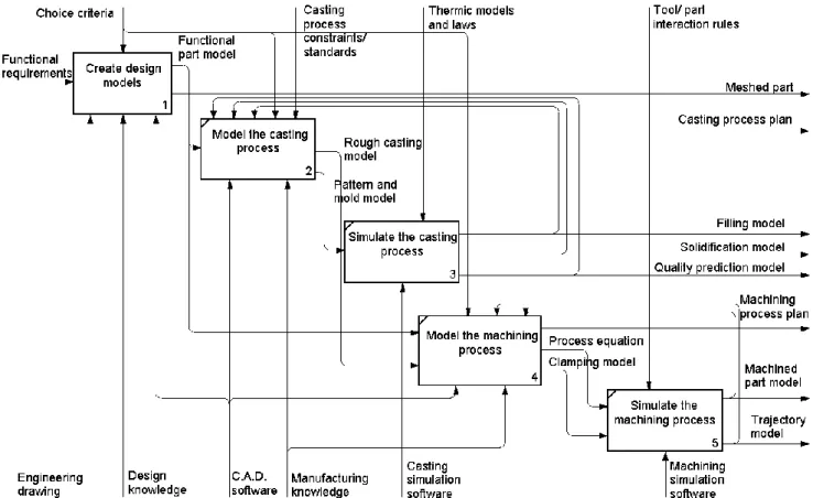
The methodology used in the present work consists in creating, in an ascending manner, the manufacturing process models. Simulation is employed afterwards to asses and to optimise the casting and machining processes. The basic steps which lead to the creation of the manufacturing models and process simulations are shown in Figure 1.
The designer creates an approximate functional model starting from the specified functions that the product must fulfil in a given volume in the desired assembly. The part’s technical functions are materialized by creating solids around these surfaces. These elements do not need to be connected but only to provide functional and mechanical capabilities. Further design allows the refinement of the solid model which will resemble the final part. The final model issued from the primary design phase will serve as a reference for the following phases. It is identified with the starting point in the creation of the manufacturing models. Additional analysis can be performed to evaluate loading behaviour through finite element analysis after the application of an appropriate mesh.
Only primary and secondary manufacturing processes are considered between the general manufacturing processes (Figure 2). After the product’s detail design, the second phase consists of the modeling of the raw material’s processing. In order to pass to the modeling of the primary manufacturing process the previous models require design modifications. They have to respond to process specifications (e.g. tapered faces to allow easy part extraction in the case of a casting process).
Figure 1: Main activities of the proposed method for manufacturing process modeling and simulation. Primary manufacturing process models are created
mainly for use in simulation. Casting processes are closed mold processes and the part is only accessible at the end of the cycle, making it difficult to draw conclusions on the part’s evolution at intermediary steps. In these cases process simulation is the only solution that provides easy interaction with the part. These simulations are performed on dedicated software which requires model transferring through normalized exchange standards (e.g. STEP, IGES). The available exchange standards do not have the capability to capture all the information and semantics contained in a model and the transferring procedure results in the loss of a certain amount of data. Thus, the model needs additional modifications and adaptation to the new environment. The designer and the manufacturing team obtain after simulation the models which will allow decision making for additional modifications and process validation.
Figure 2: General manufacturing processes [5].
Most of the times primary processing isn’t enough to obtain finished mechanical parts because of process limitations. Some part features and their dimensional tolerances are impossible to obtain through casting. In these cases full functionality is attained once secondary manufacturing processes have been employed. In the present case study machining operations have been selected and additional models need to be created. To this purpose machining features need to be identified and a machining model needs to be created. This model contains information related to operation order and tool accessibility. Simulation is then performed to assess the part’s machinability and the validation of tool trajectories. Back loops between the designer experts’ activities are necessary to indicate the fact that the models obtained through simulation serve as controls for process optimisation. These models will guide the ranking of available process solutions according to significant technological and socio-economical parameters.
3 CASE STUDY
This case study is intended to develop the previously presented methodology with the aid of a simple mechanical part as example (Figure 3). The part’s design lifecycle steps, product’s detail design along with its manufacturing process modeling and simulation, were analysed to assess the evolution of the required models and their coherence in an integrated design environment [6], [7].
The raw material needs processing by sand casting as primary manufacturing process. The cast part requires further machining by milling and drilling operations as secondary manufacturing process in order to obtain the finished part.
Models have been created for simulation purposes following this ascending methodology. Solid modeling and machining simulations have been performed using the Catia V5R17 software. As for the casting simulations, they have been performed on Magmasoft which required Rough material Casting Die casting Centrifugal casting… Forming Rolling Forging… Powder metallurgy Sintering… Special methods Lamination … Machining Milling, grinding, turning… Forging… Heat treatment Hardening, Annealing treatment… Forging… Assembly, Welding… Primary process Secondary process Tertiary process
model adaptation and transfer between the environments.
Figure 3: Mechanical part used for the case study (adapted from [8]).
3.1 Product modeling
The modeling of the manufacturing processes required product models obtained after functional definition and solid modeling. Part specifications such as functions to be assured by the part and feature tolerances and constraints directed the creation of the functional model
(Figure 4(a)). Solids were added to these surfaces to materialize the part’s technical elements (Figure 4(b)).
They aren’t connected and they are only limited by the constraints between surfaces. These models needed further refinement to obtain the final geometric model (Figure 4(c)). The parts geometric model was obtained by connecting the single elements through additional solids. The addition of volumes followed a cyclic technique and the number of iterations depended on the part’s complexity. It allowed the obtaining of the ideal designer geometric model that served as a starting point for the creation of process models. Figure 4(d) shows the meshed model obtained after meshing in the Catia environment for mechanical analysis and stress behaviour.
Figure 4: Designer models: (a) functional model; (b) intermediary solid model; (c) final solid model; (d)
meshed model.
3.2 Casting process modeling and simulation
The part’s solid model was adapted (Figure 5(a)) to respond to the technological requirements of the casting process. This implied:
the over sizing of the model, to overcome shrinkage after solidification;
the definition of a parting line; the addition of machining allowances;
the addition of a drafting angle for easy part extraction;
the suppression of those features which did not correspond to the minimum dimensions demanded by the process.
Auxiliary components such as the gating system and the feeders were designed (Figure 5(b)). The gating system’s geometry was defined as a function of the number of parts in the mold and of the molten metal’s flow speed. The feeder acts as a liquid metal reservoir and is essential for obtaining a porosity free part. It was designed as a function of the part’s volume knowing that it has to solidify after the last volume in the part.
The models of the rough casting, gating system and feeders were assembled to create the pattern model (Figure 5(c)) which was used for the design of the mold model. Since this phase was carried out in a different CAM environment, a transfer model was created which served as an input for the mold model definition and casting simulations. The pattern and mold assembly model was created using finite volumes. The strategy employed to apply the enmeshment depends on the desired results’ accuracy and on the available time for calculations. Figure 5(d) shows the pattern model obtained after enmeshment with approximately 2 million finite volumes.
Figure 5: Casting models: (a) rough casting model; (b) gating system and feeder model; (c) pattern model; (d)
meshed pattern.
The input data used to launch the casting process simulations on Magmasoft concerned the part’s material (cast iron with the liquidus temperature of about 1168°C and the solidus temperature of about 1165°C), the molds material (green sand) and the temperature dependent heat transfer. A set of models was obtained after simulation (Figure 6).
Figure 6(a) shows the flow of the molten metal through the different components of the pattern. It is used either to identify critical zones that favour premature solidification, with the assistance of a temperature scale, or to assess the correctitude of the gating system’s design with the assistance of a speed scale. The
(a) (b)
solidification model is shown in Figure 6(b). This model allows the analysis, on a time scale, of the molten metal’s evolution and the location of the last volume in a liquid state. It is used to assess the correctitude of the feeder’s design. The last simulation model is the quality prediction model. This model allows the evaluation of the part’s
quality according to the amount of porosities entrapped
after solidification
Figure 6: Casting simulation models: (a) molten metal flow; (b) solidification model; (c) quality prediction model.
3.3 Machining process modeling and simulation
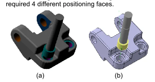
The machining process was defined taking into account the part’s final solid model, as it is the one that depicts the finished part, and the rough casting model (Figure 7(a). The latter was adapted to the machining process. The modifications that it has undergone consisted in eliminating the gating system and the feeder. This was consequent to the hypothesis that the machining process started after these components were removed.
(a) (b)
Figure 7: a) Rough casting model overlapping the finished part model; b) machining model. The creation of machining models consisted in the identification of machining features. These features contain the knowledge related to the machining process and they serve as a frame for the future process models. The feature decomposition, together with the rough casting model, acted as a starting point for the definition of the machining model (Figure 7(b)). This last model takes into account machining allowances, which were previously defined, and the solid volumes to be removed from the rough casting. It represents the intersection between the two models shown in Figure 7(a). The feature-based model was used to identify the list of machining operations according to:
the feature’s geometry;
the number of machining operations as a function of the feature’s accuracy and finish degree;
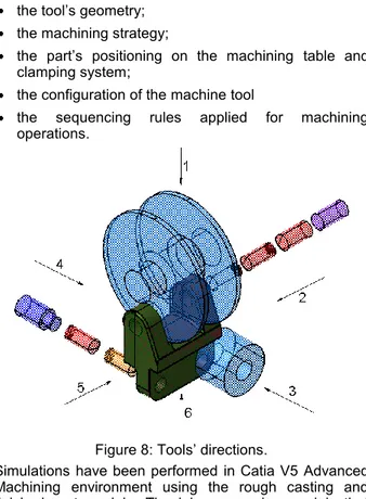
the geometrical conditions between features (used for operation grouping in order to minimise tool changes); A separate model was required for the assessment of the part’s accessibility. This aspect was modelled with the help of a characteristic polyhedron materialised by the part’s outermost faces that contain machining features. By relating this model to the tool direction model (Figure 8) it was possible to create the part’s process equation through temporal reasoning. This equation allows a certain degree of freedom during the process selection phase as it contains all the possible tool directions for the machining of a feature.
Access=3^M(2W5)^M²{[5^M(2)^M²(4)W[2^M(5)^M²(4)]}(1) Where numbers represent the defined directions, ^ is the AND operator, W is the exclusive Or operator and the M (X) syntax fixes the precedence constraints. This mathematical model defining the machining process allowed the generation of the possible process plans. Refining the machining solutions needed additional constraints defined by:
the tool’s geometry; the machining strategy;
the part’s positioning on the machining table and clamping system;
the configuration of the machine tool
the sequencing rules applied for machining operations.
Figure 8: Tools’ directions.
Simulations have been performed in Catia V5 Advanced Machining environment using the rough casting and finished part models. The job sequencing models that were previously created served as input for the definition of processing parameters. These simulations were performed taking into account different resource configurations to evaluate process capabilities and to validate the process models. Two part setups were considered which implied a variation of the number of required part positioning on the machine tool’s clamping system. The simulations were performed according to two process plans:
the processing on a 4-axis machining centre, which required only one positioning face;
the processing on a 3-axis milling machine, which required 4 different positioning faces.
(a) (b)
Figure 9: Machining process simulation models: (a) machined part model, (b) trajectory model. The simulations had as results a machined part model (Figure 9(a)) used to evaluate processing conditions. Another output of the simulations was the tool’s trajectory model (Figure 9(b)) needed to assess process coherence. This coherence is translated into valid tool
paths that allow the complete machining of the identified features without unwanted collisions.
4 DISCUSSIONS
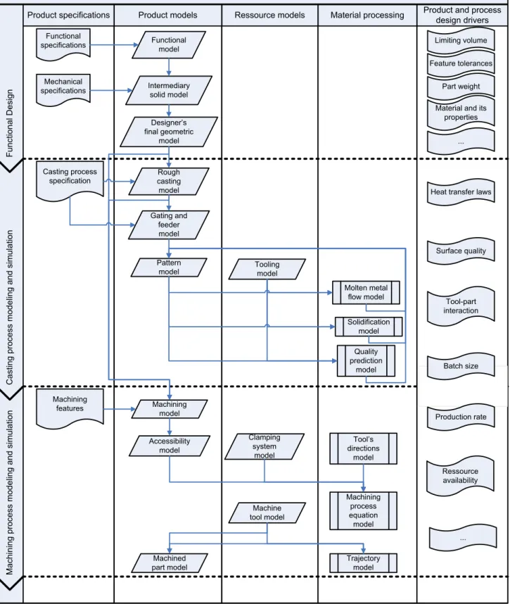
This case study was intended to simulate a concurrent engineering environment and to point out the achievable degree of integration in manufacturing process modeling and simulation. The evolution of the product’s model during the design phase is shown in Figure 10. This diagram represents an intermediary informational model acting as a framework for the integration between the product, the available manufacturing process knowledge and the associated resources. It has been used as a reference for the development of the required process plans in an integrated environment provided by Delmia’s Process and Ressource Definition.
Manufacturing process modeling and simulation F un ct io na l D es ig n C as tin g pr oc es s m od el in g an d si m ul at io n M ac hi ni ng p ro ce ss m od el in g an d si m ul at io n
Product and process design drivers Material processing Ressource models Product models Product specifications Functional
specifications Functional model
Mechanical
specifications Intermediary solid model
Designer’s final geometric model Casting process specification Rough casting model Gating and feeder model Pattern
model Tooling model
Molten metal flow model Solidification model Quality prediction model Machining model Accessibility model Tool’s directions model Machining process equation model Clamping system model Machine tool model Machined part model Trajectory model Machining features Limiting volume Part weight Feature tolerances
Material and its properties
Surface quality
Ressource availability Heat transfer laws
Batch size Tool-part interaction ... ... Production rate
Figure 10: Model evolution and design drivers. The models’ evolution is guided by different criteria:
the identified constraints and manufacturing
parameters;
the model’s behaviour; the model’s coherence.
4.1 Identified constraints and manufacturing parameters
Different constraints appear during the model’s evolution and they tend to direct the designer’s steps towards a
restrained number of choices. These constraints can appear from technological requirements. At the beginning of the functional design phase the designer is free to translate part requirements into a functional model. In order to design a robust final geometric model he needs to take into account mechanical constraints and topological limitations. The casting models take into account requirements which can be related to the part’s geometry (minimal required dimensions) or the process (flow speed, heat transfer laws). Machining models are also constrained by technological parameters such as
tool part interactions, clamping strategy (induced stress) and machining operational parameters. The simulation models provide expert knowledge to be used for process optimisation by modifying the geometrical models or the processing parameters.
Other sources for design constraints are quality requirements introduced by the specified tolerances. They are assessed after obtaining the quality predictive models. Economical constraints are materialised through imposed production rates and resource availability. They act on the definition and choice of process plans.
All these constraints are taken into account in order to limit processing solutions through multi-criteria analysis.
4.2 Model behaviour
The behaviour describes the different states that a model encounters during the product’s integrated design and the way in which the transition between them is carried out. This behaviour is either defined by specifications from the part of the designer or relationships imposed by the CAD environment. Expert rules can be used to specify the model’s behaviour through parametric tables which indicate the relationship between geometric elements.
The previously presented constraints and manufacturing parameters are employed to guide the model’s behaviour during the back loops that define the optimisation step.
4.3 Model coherence
The design methodology requires that the expert interacts with different instances of the model depicting the product at various design steps. Not only do these instances need to be coherent with each other but they also have to be coherent with external product specifications. This requires for a CAD environment to be able to assess this coherence by using an interface between the models and the external specifications.
Unfortunately, the market available software
environments do not offer this functionality.
As there is no available solution to integrate all the design phases, transfer through exchange standards between different CAD/CAM environments is required. A loss in incorporated knowledge was noticed after these manipulations. A coherence analysis is required at this level through coherence indicators.
5 CONCLUSIONS
This research work presents a methodology for the integration of the design phase lifecycle. It aims at
presenting the evolution of product models starting from functional design and continuing with the modeling of primary and secondary manufacturing processes. The simulation of these processes allowed the validation of the created models. Furthermore, the simulation models served as indicators for process optimisation from the point of view of design solutions and decision making rules for process selection.
The recommendations for further work consist in the extension of this methodology to the entire manufacturing process. The coherence indicators, as design drivers, need further development to allow the precise evaluation of the elaborated models.
6 REFERENCES
[1] Ballu, A., Falgarone, H., Chevassus, N., Mathieu, L., 2006, A new Design Method based on Functions and Tolerance Specifications for Product Modelling, Annals of the CIRP, 55/1: 139-142
[2] Martin, L., Moraru, G.-F., Véron, P., 2005, Structured CAD/CAM Models in Casting Process
Design, 3rd International Conference on Advances
in Production Engineering, Warsaw, Poland, 3: 151-160
[3] Martin, P., 2005, Some aspects of integrated product and manufacturing process, Advances in Integrated Design and Manufacturing in Mechanical Engineering, Part 2: 215-226
[4] Bernard, A., Perry, N., 2003, Fundamental concepts
of product/technology/process informational
integration for process modelling and process planning, International Journal of Computer Integrated Manufacturing, 16: 557-565
[5] Ashby, M.F., Michael, F., 2004, Materials selection in mechanical design, Butterworth-Heinemann publishers, Oxford, ISBN: 9780750643573
[6] Godot, X., Siadat, A., Martin, P., 2007, Proposition d’une méthodologie de modélisation géométrique
en contexte collaborative, 5th International
Conference on Integrated Design and Production, Rabat, Morocco
[7] Skander, A., Roucoules, L., Klein-Meyer, J.S., 2008, Design and manufacturing interface modelling for manufacturing process selection and knowledge synthesis in design, International Journal of Advanced Manufacturing Technology, 37: 443-454 [8] Halevi, G., Weill, R.D., 1995, Principles of Process