HAL Id: hal-01767890
https://hal.archives-ouvertes.fr/hal-01767890
Submitted on 16 Apr 2018
HAL is a multi-disciplinary open access
archive for the deposit and dissemination of
sci-entific research documents, whether they are
pub-lished or not. The documents may come from
teaching and research institutions in France or
L’archive ouverte pluridisciplinaire HAL, est
destinée au dépôt et à la diffusion de documents
scientifiques de niveau recherche, publiés ou non,
émanant des établissements d’enseignement et de
recherche français ou étrangers, des laboratoires
The introduction of VHDL in digital design practical
courses
Catherine Douillard, Pascale Ferry, Patrick Adde, Michel Jezequel
To cite this version:
Catherine Douillard, Pascale Ferry, Patrick Adde, Michel Jezequel. The introduction of VHDL in
digital design practical courses. 1st european workshop on microelectronics education (EWME) , Feb
1996, Villard de Lans, France. �hal-01767890�
The introduction of VHDL in digital design practical courses
Catherine Douillard, Pascale Ferry, Patrick Adde, Michel Jézéquel
Département Electronique, ENST de Bretagne, BP 832 29285 BREST CEDEX, France
e-mail: [email protected] / [email protected] / [email protected] / [email protected]
This paper deals with the impact of the introduction of VHDL modelling into the VLSI design course taught at Télécom Bretagne. In particular, its effects on the progress of the design project proposed every year to the students are analysed. The advantages and drawbacks of the use of simulation and synthesis tools are explained.
1. Introduction : specialising in Electronics at Télécom Bretagne
The third-year students at "Télécom Bretagne", a French Telecommunications engineering school, may specialise in "Electronics for Telecommunications". The fields covered by this option are Electronics, Microwaves and Optics. They choose their speciality field definitively after 6 weeks. The Electronics Department, composed of 8 lecturers, is in charge of the first specialisation. During a 14-week period, the students have the opportunity to discover different aspects of integrated circuit design. The overall course content is divided into one third concepts, one third methods, and one third tools. Taught courses take up 55% of their study schedule and cover CAD tools and methods, digital systems and circuit architectures, CMOS design, telecommunication components, analogue techniques and technologyIn addition, an active educational method focuses on a VLSI design project which takes up the other 45% of their time. Beginning with given specifications, they have to design a complex digital circuit with the help of two or three lecturers. Mostly, the topic of the project is based on the development activities of the department. In general, there are 2 or 3 projects running concurrently.
2. Design method used
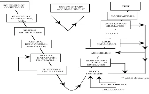
The students discover the world of integrated circuits in a very short time. They therefore follow a specific method, suited to the circuit, to the technology used, and to the tools at their disposal. The different steps of the design method used are shown in figure 1. The first phase, known as the "down" phase, consists of specifying the circuit from behavioural and functional studies. The second phase, or "up" phase, deals with structural and physical aspects. This method, called the "V method", repeats the classic development of design methods [1], adapted to the technology of gate-arrays or standard -cell circuits, but takes into consideration the hierarchical description of the circuit.
**
M AC RO LIBR AR Y C ELL LIBR AR Y
** with fa ult simulation BLOC K S YNTHES IS POS T-LAYOUT SIM ULATION LOGIC SIM ULATION LAYOUT MANUFAC TUR E TEST FEASIBILITY, TECHNOLOGY, AR EA SC HEDULE OF CONDITIONS GENER AL B EHAVIOURAL SIM ULATION GEN ER AL ARC HITEC TUR E
BLOCKS , DATAPATHS , I/O, C LOCKS, . .. FUNCTIONAL S IMULATIONS ELEM ENTARY LOGIC SIM ULATION ASSEMB LING DOC UM ENTARY ACC OMPANIMENT **
Figure 1 : "V method" used
3. The introduction of VHDL modelling into the design project
The project example detailed in this paper deals with a new family of error correcting codes called turbo-codes [2], which were invented at Télécom Bretagne in 1990. The function of the part of the circuit that the students had to design dealt with the implementation of an original auto-synchronisation method for turbo-encoding/decoding circuits.
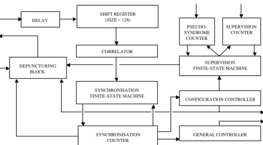
This method provides the timing synchronisation necessary to trigger the intrinsic functions of a turbo-decoder such as interleaving or deinterleaving. It also takes into account elementary decoder synchronisation to remove any ambiguities about the position and/or the inversion of the symbols coming from the transmission channel after demodulation. The two types of synchronisation are performed simultaneously without any synchronisation word or loss in the coding rate. The ambiguities due to demodulation are removed in the case of base-band, BPSK and QPSK modulations. A pseudo-syndrome concept for decoder supervision in the tracking phase is used [3]. The decoder is thus able to detect out-of-synchronis ation reception and to start a new synchronisation research phase. From a functional point of view, the synchronisation circuit is organised as presented in figure 2. This figure shows the different kinds of functional blocks and their interconnections. The corresponding circuit only represents 4000 logic gates but is functionally complicated and requires very long validation sequences owing to the fact that it is composed of many sequential intercommunicating blocks.
Figure 2 : functional scheme of the synchronisation part of a turbo-decoding circuit This project was proposed twice to the students, in 1993 and 1994. In 1993, the design was undertaken without using VHDL modelling. The students started with a system level study of the circuit specifications (for 4 to 5 weeks). This study included behavioural simulations from C programs to define synchronisation criteria. Functional division was performed and a classic hierarchical design carried out down to logic or layout level. During the latter stage, the design task was shared up among the students and performed through the use of professional CAD tools. In the case of the synchronisation circuit presented above, functional division and block design were performed without any problems (6 weeks for the study of specifications and functional organisation, and 6 weeks for the design of blocks). When the students arrived at the assembling phase of the logic design, problems began to occur at the block interfaces : a fairly large number of errors appeared concerning the definition and function of signals and buses providing communication between the various blocks of the circuit. Consequently, the assembly was particularly difficult because of the numerous interconnections between the different blocks. Finally, the adjustment of the whole circuit was left uncompleted because most errors led to significant design modifications. It was a pity that the students could not draw lessons from these errors, and they were themselves a little disappointed because they did not obtain any global results.
The introduction of behavioural modelling with VHDL one year later significantly affected the design project progress. The logic design phase was delayed and architectural choices and block level description were validated first, through functional simulations as presented in figure 1. When assembling the VHDL
DELAY SHIFT REGISTER (SIZE = 128) CORRELATOR SYNCHRONISATION COUNTER SYNCHRONISATION FINITE-STATE MACHINE PSEUDO- SYNDROME COUNTER SUPERVISION COUNTER SUPERVISION FINITE-STATE MACHINE CONFIGURATION CONTROLLER GENERAL CONTROLLER DEPUNCTURING BLOCK
descriptions of blocks, the students came up against the same problems with the block interfaces. But, as they discovered their errors much earlier in the project, (after 8 or 9 weeks) they had the opportunity to correct them before beginning logic design. Globally, the synthesis task was not completed after 14 weeks but finally led to significantly less residual errors afterwards. This second design was quickly completed without any problems.
Recently, automatic logic synthesis has also been introduced into the project which has permitted the logic design stage to be completed within the 14 weeks. Now, the students are asked to write a synthesisable VHDL description of the circuit. This description is used both for functional validation and as an input for the synthesis tool. From a schedule point of view, the logic design period has been approximately reduced by half (4 weeks instead of 8). But synthesis results are sometimes a little surprising : in general, students rarely question the RTL descriptions they provide the tool with, and do not doubt the results obtained. For instance, they are usually not surprised when the synthesis tool uses 32 D flip -flops to build a simple 4-bit counter, or adds sequential operators in combinatorial functions. That is why the correct use of such tools requires emphasis to be laid on logic design techniques so that beginners can appreciate the synthesis results.
4. Conclusion
High level modelling languages and related simulation and synthesis tools are becoming more and more necessary when designing digital systems because of the constant growth in the complexity of circuits. From an educational point of view, the introduction of such techniques has brought fairly big changes in VLSI training methods : with high-level simulation tools, most errors are detected at an earlier stage, but the use of synthesis tools is often tricky. Besides, the use of such tools is fairly heavy and introducing them into such a curriculum is therefore only of interest when the project is so complex that the students can perceive their real necessity. It may thus be difficult to manage to find topics for projects which can be completed within 14 weeks.
References
[1] D. D. Gajski, "Silicon compilation", VLSI System Design, pp.48-64, Nov. 1985. [2] C. Berrou, A. Glavieux, P. Thitimajshima, "Near Shannon limit error-correcting
coding and decoding : turbo-codes", in Proc. ICC'93, Geneva, May 1993. [3] C. Berrou, C. Douillard, "Pseudo-syndrome method for supervising Viterbi