Science Arts & Métiers (SAM)
is an open access repository that collects the work of Arts et Métiers Institute of
Technology researchers and makes it freely available over the web where possible.
This is an author-deposited version published in:
https://sam.ensam.eu
Handle ID: .
http://hdl.handle.net/10985/10189
To cite this version :
Robin KROMER, Sophie COSTIL, Jonathan CORMIER, Damien COURAPIED, Laurent BERTHE,
Patrice PEYRE, Michel BOUSTIE - Laser surface patterning to enhance adhesion of plasma
sprayed coatings - Surface and Coatings Technology - Vol. 278,, p.171–182 - 2015
Any correspondence concerning this service should be sent to the repository
Laser surface patterning to enhance adhesion of plasma sprayed coatings
R. Kromer
a,⁎
, S. Costil
a, J. Cormier
b, D. Courapied
c, L. Berthe
c, P. Peyre
c, M. Boustie
ba
Univ. Bourgogne Franche-Comté, UTBM, IRTES EA7274, F-90100 Belfort, France
b
Institut Pprime, Physics and Mechanics of Materials Department, UPR CNRS 3346, ISAE-ENSMA, BP 40109, 86961, Futuroscope Chasseneuil, France
cPIMM, UMR 8006 CNRS, Arts et métiers ParisTech, 151 Bd de l'Hôpital, 75013 Paris, France
a b s t r a c t
Keywords:
Laser surface texturing Thermal spraying Surface topography Adhesion tests Adherence
In thermal spraying, adhesive bond strength is a feature of surface properties. An adapted surface is studied with prior-surface treatments to enhance interface energy. This study deals with Ni–Al coatings on 2017 aluminum alloy substrate produced by atmospheric plasma spraying. The adherence was evaluated with several controlled surface topographies obtained by grit-blasting and laser surface texturing technique. Adherence has been tested with two different techniques: pull-off test and LASer Adhesion Test. They induce different stresses at the inter-face. The results showed that the adhesive strength is mostly controlled by a contact adhesion area. A large con-tact area increases the energy release rate at the interface during coating failures. The bond strength tendency for the two adherence tests is similar: apparent adherence is tripled thanks to laser surface patterning. Fracture propagation is stopped nearby laser-induced holes due to the complex shape and has to deviate inside the coat-ing to maintain crack propagation (inter-splat cracks). The energy at the interfaces becoat-ing stored locally due to pattern: pattern morphology, pattern localization and powder feed rate are important factors that control the ad-hesion strength of the thermally sprayed coatings.
1. Introduction
The adhesion strength of thermal sprayed coating depends strongly on the substrate surface: temperature, topography and nature[1]. For instance the preheating of the substrate, generally achieved with the plasma spray jet, is thus a key issue to obtain good splatting[2]. Oxide layer is formed especially for metallic substrate[3]. Substrate surface nature changes the contact quality (desorption of the pollutants adsorbed on the surfaces and the droplets wetting)[4]. Substrate and coating temperatures during spraying also control residual stresses dis-tribution[5].
Surface contaminations such as oxides, carbon or oils have to be re-moved from a metallic surface before itsfinal use as they change the physico-chemical behaviors and/or surface topography[6]. Among the conventional techniques, degreasing and grit-blasting are used in most cases before thermal spraying. The degreasing agent leads to chemical modifications of the surface while grit-blasting modifies the surface morphology by creating a random roughness thus promoting a mechanical anchorage of the incoming particles to the substrate[7]. This technique is very effective for most materials except for ductile ma-terials that may be damaged with a risk of micro-crack nucleation on the surface[8]. In addition, grit inclusions can occur decreasing the ad-herence of the subsequent coating. New technologies such as laser tools are developed to adjust the coating/substrate adhesion. Shortly,
laser tools have been shown to improve surface behaviors of materials as surface treatment techniques (for cleaning purposes, topography modification, heating treatment, etc.)[9–13]. Lasers present advantages such as easy automation, localized treated area, three dimensional treat-ments and greatflexibility. Using a controlled ablation technique, topol-ogy modifications may occur for all types of materials such as glasses, ceramics, polymers and metals[14]. A specific laser tool adapted to the material to be treated (in terms of wavelength, pulse duration, spot size and pulse energy) added to a scanner for 3D shape modi fica-tion can promote mechanical adherence for thick coating elaborated by thermal spraying. Those parameters influence logically the topogra-phy but also the material microstructure due to the heatflux which can be absorbed during the treatment according to the pulse duration
[15–17]. Laser–matter interaction is commonly described considering three main factors: laser light, material and environment. Conversion of absorbed energy via collision processes into heat is the most important effect that occurred during the laser interaction up to the va-porization of micro-metric layers through ablation phenomenon corre-sponding to the fast transition from the overheated liquid to a mixture of vapor and drops (laser surface texturing)[18,19]. Short pulse dura-tion (10−10–10−15s) is needed to localize the laser interaction on the
extreme surface[20].
Coating substrate systems need to be quantitatively tested to evaluate in-service life span. Adhesion is related to the nature and strength of the bonding forces between two materials in contact such as ionic, covalent, metallic, hydrogen and Van der Waals forces
[21]. But it is also essential to evaluate mechanical anchoring (or
⁎ Corresponding author.
E-mail address:[email protected](R. Kromer).
http://dx.doi.org/10.1016/j.surfcoat.2015.07.022
interlocking) which is usually recognized as the main bond strength contributor in thermal sprayed coating[7]. This is why in this paper, a comparison between conventional method (grit-blasting) and laser surface texturing has been carried out with Ni–Al coating on 2017 aluminum substrate systems[22]. Different surface topogra-phies will be presented in this paper and characterized with the use of 2 adhesion tests. Furthermore, considering some specific field such as thermal barrier coatings (TBC), laser surface patterning could be a solution to remove bond coat by an application oriented surface topography (hence decreasing the processing costs and min-imizing the number of parameters controlling the durability of a TBC coating system).
2. Experimental procedure 2.1. Materials
2017 aluminum alloy substrates (Mg = 0.6%, Cu = 4%, Mn = 0.7%, Fe = 0.7% and Si = 0.5% weight), widely used in aerospace structural ap-plications, have been used in this study (solution heat treated, and natu-rally aged to a substantially stable T4 condition). The substrates were 25 mm in diameter and 10 mm thick buttons and 50 × 30 × 1 mm3plates
(roughness corresponding to Ra≈ 0.4 μm). As a ductile material, 2017 Al alloy presents weakening issues (cracks due to abrasive granules) during conventional surface pre-treatment[23].
The powder, deposited on the substrates, was Ni–Al powder (95–5% weight, AMDRY 956, Sulzer-Metco) and the particle size varied from 45μm to 90 μm (d0.1–d0.9) with a 67μm average grain size.
2.2. Substrate surface pre-treatment
To ensure substrate surface pre-treatments, several processes have been carried out. Grit-blasting (GB) was performed by“Econoline” ma-chine (Econoline Abrasive Products, USA) (self-contained, recycling, sealed glove box design). Samples were treated with 3 bars pressure at 5 cm stand-off distance and 70° angles to obtain roughness of Ra≈ 3 μm and Rz ≈ 16 μm.
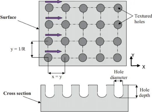
Laser experiments were conducted with a pulsedfiber laser (Laseo, Ylia M20, Quantel France), operating with a 1.064μm wavelength, a 100 ns pulse duration, a maximum mean power of 20 W and repetition rate varying from 20 to 100 kHz. The circular laser beam exhibits a 60μm diameter and a Gaussian energy distribution. The surface pattern-ing technique consisted of series of equidistant lines of holes coverpattern-ing the whole surface. Various parameters can be selected like the number of shots per drilled hole, the laser energy density, the laps time between two shots as well as the hole area density to achieve the surface texture
[24](seeFig. 1).
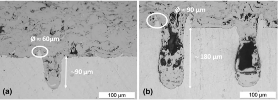
Suitable type of laser and adequate setting of processing parameters are necessary in order to tailor textures. The adhesion of thermal-sprayed coatings on textured substrates would be highly influenced by the pattern geometry and“additional” surface roughness (spatters and recast material), as they modify the surface contact area of the sub-strate. Particularly, the optimal cavity dimensions must be adapted de-pending on the sprayed powder average size and viscosity that control the wettability of holes. As shown inFig. 2, the molten splats during coating do not easilyfill deep holes[25]. Moreover, the shape and depth of holes need to be optimized to minimize stress-concentration effects which usually degrade the mechanical properties of the sub-strate (like fatigue behavior).
As many adhesion areas can be obtained on textured surfaces, de-pending of the shape, height and density of holes, one of our assump-tions was to select hole volumes equal to the sprayed powder average volume (d0.5) to enable fullfilling. Considering the mean size of
spheri-cal Ni–Al particles equal to 67 μm in diameter, we found a particle vol-ume equal to Vparticle= 4/3πR3≈ 150,000 μm3. A similar volume was
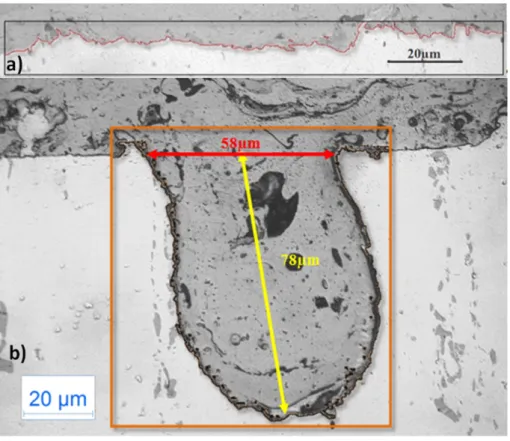
obtained with drilled holes having diameter equal to 60μm and a depth of 80μm, which have been considered for texturing, using 40 local pulses at 20 W mean power and 30 kHz, at the focal point position. The laser holes were oriented at 0° and 30° from the surface to ad-dress orientation effect (Fig. 3), and the hole distribution was varied into four matrixes detailed as follows: F[L]− bDN with [L] the dis-tance between two holes in X and Y directions andbD N the angle versus the surface normal. 100, 150, 200 and 300μm have been stud-ied for [L] and 0, 30° and−30/+30° in staggered rows for bDN. An example of P200–30 condition is shown inFig. 4for top and
section views. The hole morphology was shown to oscillate around a mean value depending on the laser–matter local interaction in nano-second regime.
2.3. Characterization methods 2.3.1. Adhesion tests
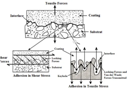
Many methods have been used already for the evaluation of the coating-substrate adhesion. A significant number of them are based on the linear elastic fracture mechanics approach[26]. The best test method for a given coating is often the one that simulates as close as possible the in-service loading. Adherence tests give values for only one system and as shown inFig. 5, a unidirectional test will de-velop locally different stresses (multi-scale effect)[27]. Hence the adhesion of the coating was qualitatively assessed by using two methods: tensile adhesion test (pull-off test) and LASer Adhesion Test (LASAT), in order to evaluate macro-tensile and micro-tensile effect on adhesion.
The coating adhesion wasfirst tested in a manner similar to that de-scribed by the DIN EN 582 (ASTM Standard C633). 25 mm diameter but-ton samples were joined with cylindrical counter-parts using an adhesive agent (FM1000)[28,29]. A constant displacement (1.026 mm/min) was applied to the counted parts with a tensile test machine (50 kN–500 mm ESCOTEST) up to complete failure. The maximum force was then attributed to the adherence at the interface calculating the ratio between the force and the tested area[30]. This test applies tensile and shear stresses at the interface.
The LASer Adhesion Test (LASAT) was used as a contactless tech-nique to generate high-level of dynamic tensile stress at an interface
[31].Fig. 6shows a schematic view of the LASAT test.
The technique uses a shock wave produced by a laser-induced plasma and applied, in our case, to the substrate–coating system to be tested[32]. The plasma induces a fast surface compression and re-laxation propagating in the samples leading to a volume movement up to the rear surface. The laser shock waves arefirst initiated on the substrate surface (back side) then propagate inside the system towards the coating. The crossing of incident and reflected release waves at the rear free surface, can produce local uniaxial tensile stresses inside the target (Fig. 7) and possible debonding at the inter-face[33]. The Laser used is a GAIA_HP from Thales company (Nd; YAG— 7.1 ns–532 nm). The diagnostic of failure is carried out by measuring the rear free surface velocity by a Velocimeter Interfer-ometer for Any Reflector system (VISAR)[33]followed by cross-sections of impacted zones to characterize the damage generated by such a dynamic solicitation. For a given coated system and laser duration, a laser intensity debonding threshold is then determined by increasing step by step the laser power density (in GW/cm2).
The adhesion strength value (GPa) is then identified with numerical simulation of shock wave propagation inside the material reproduc-ing experimental free surface velocity data[34].
LASAT was performed on 80μm Ni–Al thick coatings sprayed onto 1 mm Al2017 thick substrate. Those thicknesses are adapted to have maximum energy near the interface (thickness linked to the sound speed in the coating)[34]. Indeed, the characteristics of the shock wave (pressure level, duration, shape…) are directly linked to the
Fig. 2. Optical microscopy in cross section micrograph of plasma-sprayed AMDRY 956 (Ni5Al) powder onto aluminum AISI 2017 textured at different conditions[23]: a) 10 W, 40 kHz, 32 pulses, b) 17.3 W, 20 kHz, 48 pulses (laser variables).
pulse and confinement parameters used during the LASAT. Therefore, considering the experimental parameters (water confinement, 7.1 ns@ 532 nm pulse), it is possible to show that the crossing of the releases waves which generates the traction occurs near the interface (Fig. 8). Shock wave energy to break the interface has been statistically checked with 6 pulses at the same energy.
2.3.2. Morphological analyses
Surfaces were analyzed before and after the coating process. The characterization of the morphology of the pre-treated samples with-out and with coating was performed by optical microscopy (Moz2 Zeiss) and by scanning electron microscopy (SEM Jeol JSM-6400). Both surface and cross section observations were performed using the cross section images, the interface area being determined by image analysis using the fractal approach[35]. Contact area per sur-face unit will be considered in the following as a criterion for me-chanical adhesion.
Fig. 9introduces the three steps for analyses: (1) a small area is con-sidered from a previous microscopy image, (2) threshold treatments
define the substrate/coating boundary and (3) ImageJ software com-putes the developed interface edge length, which is equal to the adhe-sion area for grit-blasting. Similarly, for laser surface patterning, it is possible to compute the hole interface length from a cross-section view and to calculate the interface area for one pattern (Dundurs equa-tion). The pattern enables evaluating the complete adhesion area by taking into account both textured and non-textured areas. We could then define (Eq.(2)) an interface or adhesion area ratio R, which repre-sents the degree of the interface area compared with an equivalent pla-nar (as Ra for profilometer analysis):
R¼Adhesion AreaPlane Area : ð1Þ
Ten image analyses for each treated surface (different samples) were carried out to estimate R to statistically provide reliable data.
Table 1confirmed that the adhesion area ratio could be modified strongly depending on the wavelength pattern (in-between 1.7 and 7 for laser texturing, compared with 2.7 for the grit-blasting). Each hole considered separately adds around 11 times more adhesion
Fig. 4. Top view and cross section of a F200-30 matrix.
area than aflat surface.Fig. 10represents the interface of a grit-blasted and laser treated surface computed with the image analysis to obtain the real interface area.
2.4. Coating production
Coatings were produced by atmospheric plasma spraying (APS), using a F4 torch (Sulzer-Metco). The torch was mounted on a XYZ
robot (ABB robot) to spray samples. During coating, samples were rotat-ed in front of the torch while the torch followrotat-ed a vertical movement allowing a homogeneous coating deposition. Samples were cooled down to room temperature by an air cross-jet perpendicular to the sub-strate (Fig. 11). For pull-off and LASAT tests, 300μm and 80 μm thick coatings were produced on buttons and plates respectively. Ni–Al coat-ing was deposited uscoat-ing standard thermal spray parameters, as shown inTable 2.
Fig. 6. Shock wave production by laser plasma in confined regime.
Fig. 7. Space vs time diagram square pressure loading— without and with cracks[32].
Fig. 8. a) Space–time (x–t) diagram of shock waves, created by the loading, and expansion waves in a target in its representative states along the propagation time: 0 for initial state, 1 for shocked state, 2 and 3 for released state and 4 is a traction state resulting from the interaction of states 2 and 3; b) numerical modeling of spallation of the samples with LASAT test; c) maximum tensile stress alighted at the interface.
3. Results
3.1. Tensile adhesion test
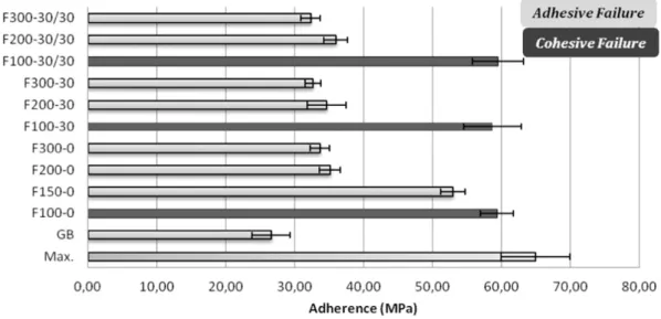
Tensile adhesion tests were performed on coatings formed onto laser irradiated surfaces and grit-blasted Al2017 substrates in order to evaluate the surface preparation effect.Fig. 12represents adherence values with standard deviation (GB = Grit-blasting
and F[L]− bD N = [L] distances between holes and bD N holes orientation).
Grit-blasting provides an adhesive failure similar to previous data, namely an adhesive debonding at about 25 MPa.
Concerning laser texturing, the following observations were made: (1) The drilled-hole angle has almost no effects on the adherence
values, but the global texturing matrix affects bond strength logically.
(2) An increase of the adhesion strength was systematically shown to occur with the laser surface treatment compared to conven-tional methods. 52 MPa, 35 MPa and 34 MPa values were obtain-ed for P150, P200 and P300 matrices respectively.
(3) A cohesive failure of 60 MPa was obtained with P100 matrix.
Fig. 9. Procedure to isolate the interface— 1/isolate a picture near the interface, 2/change threshold to have in black the coating and white the substrate and 3/evaluate the limit between black and white areas.
Table 1
Adhesion area ratio for the different surface pretreatments.
Techniques GB P100 P150 P200 P300 Ratio 2.7 7.0 3.7 2.5 1.7
Fig. 13illustrates different fracture modes for grit-blasting and laser patterning surface (two types of failure: adhesive and cohe-sive) according to cross-sections before and after tensile adhesion tests. A mixed-mode failure was evidenced for patterned surface. As coating seems to be trapped in holes, the anchoring role of holes is well demonstrated.“Apparent” adherence is more judiciously mention here than adherence. The interface shape of texturing sur-face causes an increase of crack energy release rate at the intersur-face with local stresses direction. Conditions for crack-tip release rate in the coating are fulfilled due to the holes shape and applied stresses. Critical hole morphology should be found to have cohesive failure above holes.
Pull-off test allows a macroscopic characterization and locally tensile and shear stresses at the interface are present. Another test has been used (LASAT) inducing only tensile stresses at the interface for the cho-sen configuration in order to try to separate both contributions. 3.2. LASAT
The LASAT bond test allows creating a near 1-D tensile stress loading in a local area.Fig. 14shows an example of LASAT tested specimen, after 17 impacts at an increasing laser power density. The reliability of such a simple and fast diagnostic has been confirmed by post-mortem inspec-tion of the coating-substrate cross-secinspec-tions coupled with velocimetry analysis. Complete coating expulsion can be noticed for high energy shock wave.
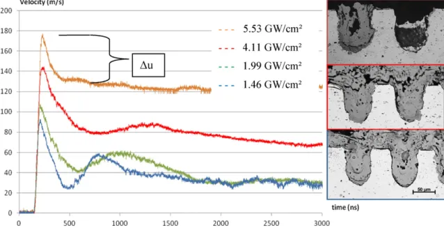
VISAR technique provides a precise determination of bond strength with shock wave propagation theory.Fig. 15represents free surface ve-locity measurements for different laser-power densities (and resulting plasma pressures) applied at the surface of the sample. At low power density (1.46 to 4.11 GW/cm2), the shock wave reflections on the back free surface are easily evidenced, indicating that no interfacial fracture has occurred after one way in, whereas, for 5.53 GW/cm2, the absence
of large secondary reflected peaks indicates that debonding has oc-curred. Laser shock waves could not be transmitted through the inter-face towards the coating side. A power density threshold could be determined.
The signal is evaluated and checked with cross-sections to see if there are cracks at the shock wave interaction area. Hence it is possible to determine the interface delamination. The debonding strength (σd)
can be evaluated according to previous works[35]: σd¼
1
2ρ0C0Δu ð2Þ
whereρ0is the density of the material, C0is the bulk material sound
ve-locity andΔu is the velocity jump from the top of the peak to the take-off point (Fig. 15). The velocity jump is equal for any shock wave broken at the interface.Fig. 16shows the debonding strength (Eq.(2)) for dif-ferent surface preparations (grit-blasting and 3 matrix laser texturing) with standard deviation.
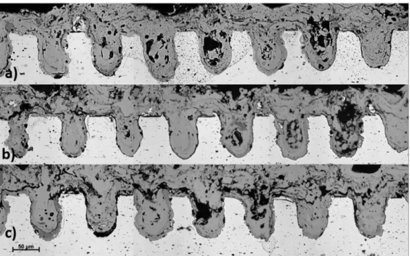
The necessary energy to break the interface for laser treated surface is higher than conventional method. Interface does not break for tighten matrix for two hole matrices and with the same shock wave energy (Fig. 17-a/b). The crack decelerates when obstacles are encountered but the accumulated energy might be sufficient to provoke a cohesive
Fig. 11. Thermal spray configuration.
Table 2
Thermal spray parameters defined for NiAl powder.
Primary gasflow rate [SLPM] AR 50
H2 8
Spray distance [mm] 120 Arc current [A] 600 Powder feed rate [g/mm] 27 Carrier gasflow [l/min] 3.3 Angle injection [°] 75
failure (Fig. 17-d). But the nearby holes have friction effects on the others (Fig. 17-c).
Cracks might be stopped by some holes (Fig. 18-a) and/or go around (Fig. 18-b) and/or go through (Fig. 18-c) for different shock wave ener-gies. Last possibility seems to be dependent on splat shape resulting from spreading and solidification. Indeed the inter-splat interface is an easier path for crack propagation.
LASAT results are in qualitative agreement with the tensile pull-off test results. Quantitatively strong difference of bond strength values due to the quasi-static and dynamic applied stresses is noticed. Compar-ing GB and F100-0 adhesion tests, bond strength is three times larger for both tests. The interface resistance tends to increase with tightened pat-terning (from F100 to F300). In both cases, it is necessary to have a larg-er enlarg-ergy applied to break the intlarg-erface due to mixed-mode failures. 4. Discussions
Quasi-static and dynamic stresses have been applied to found adhe-sion bond strength for NiAl–Al2017 couple with different prior surface treatments. The results have shown an interesting mixed-mode failure improving adherence values with laser treated surface. The patterns lock coating particles in (mechanical anchoring and friction properties). The failure mechanisms will be detailed and a correlation with total ad-hesion area will be proposed.
Laser surface texturing enhances adhesion bond strength (up to three times) for several reasons. Cracks normally follow the interface for a
Fig. 13. Observations representing the interface before and after tensile test for grit-blasted surface, 100μm distant holes and 200–300 μm distant laser holes.
Fig. 14. Typical images of a LASAT tested coated specimen, (a) substrate side and (b) coating side for increasing laserfluxes — in circled shock wave induced de-bonding has occurred.
maximum applied force. Irregularities on the surface increase the energy necessary for the crack to propagate. Holes create uneven adhesion sur-face locally (around 11 times) so crack energy increases up to coating co-hesive failure. Coating fracture toughness being larger than interface fracture toughness, the apparent adherence values consequently increase. With tightened matrices, obstacles are abundant. Less energy is needed to go through the coating than to try to follow interface. Mixed mode failure might be predicted for one patterning thanks to numerical analysis know-ing crack-tip energy release rate and cohesive toughness of the coatknow-ing (mixed-angle at the interface). It is not necessary to have complex mor-phology. If the angle is above a certain value, there is cohesive failure above hole. Assuming the fracture toughness of the interface be Gicand
that of the coating to be Gcc. Then the crack is likely to continue along
the interface based on the linear elastic fracture mechanics. If the condi-tion Gi≤ Gicis met, where Giis the crack-tip energy release rate for a
crack along the interface. Or it can be deflected in the coating if the condi-tion Gc≤ Gccis met, where Gcis the crack-tip energy released in the
coat-ing. Since the fracture toughness of the metal is much higher than the coating (due to the micro/macrostructure) and the interface ones, the possibility of the crack kinking into the metal may be ruled out. So there is a limit hole morphology to have deflection in the coating (due to strong locally phase angle changing increasing the energy necessary to follow the interface). Thus the crack kinking is the main contributor to the en-hancement of the interface. The cohesive failure can be further divided
into micro-kinking and intended-kinking. The adherence test gives stron-ger values for intended-kinking than micro-kinking respectively for ap-parent adhesion area of pattering surface nearby the adhesion area of grit-blasting surface. In this way, controlling the developed interfacial sur-face, the adhesion area needs to be as high as possible to improve the coating adhesion and create regular sharp angles at the interface. In per-spective where the grit-blasting surface preparation is not enough and a bond coat is applied (for several reasons) an adapted surface could be provided to coatings and use phases to decrease processing costs and minimizing the number of parameters controlling the durability coating system.
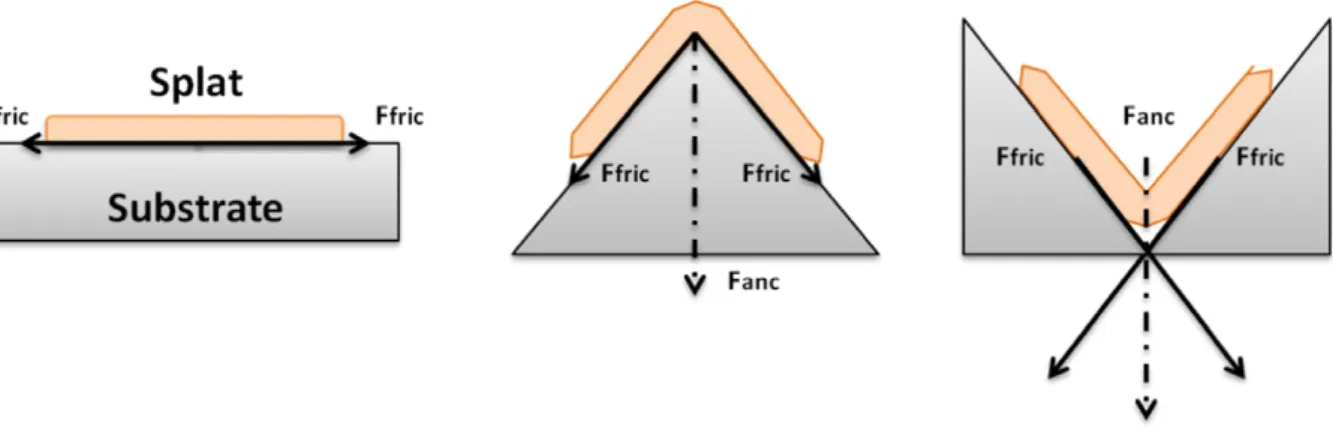
During thermal spraying, thefluid recedes on the surface; some coat-ings are trapped on the surface and with solidification created quenching stress. The quenching stress is therefore given by the product of the misfit strain and the modulus of the deposit. Mechanical cramping is dependent of the frictional forces (Fig. 19) and blocking mechanisms.
Suppose that a thin object is placed on an inclined plane (Fig. 20). If pressure P is applied to the interface between the object and the slope, the friction force f is characterized as:
f¼ μPs ð3Þ
whereμ and s are friction coefficient and the contact area respectively. fv
Fig. 15. Experimental free surface velocities of F100-0 with debonding (at 5.53 GW/cm2
) and without coating debonding (for the other three laser power densities).
is the force needed to remove vertically the object:
fv¼ f cosθ: ð4Þ
It shows that removal force fvis proportional to the projection area. If
a thermally sprayed coating fullfill the rough surface that is expressed as the following function in orthogonal coordinate:
z¼ f x; yð Þ: ð5Þ
Then, the force dfvto vertically remove the deposit on the in
finites-imal area ds of the surface is expressed as:
dfv¼ μPds cos θ ð6Þ
whereθ is the angle between tangent and normal of the infinitesimal area.
Fig. 17. Samples failures of LASAT test: a-c) 100μm matrix, b-d) 200 μm matrix.
The least force to separate perpendicularly the deposit from the rough surface domain D is:
Z D dfv¼ Z SμP cos θ ds ¼ μP Z S cosθ ds ð7Þ
replacingμ and P on each area by their mean. It is possible to determine F adhesive strength: F¼ μP Z S cosθ ds D : ð8Þ
Adhesive strength can then be theoretically predicted thanks to the equation below with R ratio computed with image analysis:
F¼ μPR: ð9Þ
The mechanical adhesion so is linked directly to the factor R identi-fied with image analysis presented earlier. The adhesion area being larg-er for laslarg-er surface pattlarg-erning, larglarg-er adhlarg-erences values are expected. Adherence values have been shown to be linearly dependent to R (sur-face in contact ratio).Fig. 21presents the adherence (a) and debonding strength (b) as a function of R for different surface preparations and for both pull-off and LASAT characterization techniques.
First cohesive failures above each hole correspond to intended-kinking (increasing strongly the adherence value). In the case a) a strong difference for a same R adherence values are noticed between GB and LST. Holes are linearly distributed so linearly proportional to R, the slope increase so. The adherence values for LST are adhesion bond
strength and cohesive bond strength. GB seems limited to increase ad-hesion bond strength.
Second the adherence value can be determined for the closest matrix (in the test: cohesive failure) as demonstrated inFig. 21(a). In dotted line is presented the adherence value obtained by pull-off test com-pared to an unbroken line the analytical adherence value for this pat-tern: 116 MPa. A cohesive failure in this case (the test limit would be reached) is logic. Moreover for a polished surface, R equal to 1, the ad-herence is around 11 MPa (validated by the measurements).
A numerical analysis of crack propagation for different stresses needs to be developed to go forward (will be detailed in a further paper). Optimal pattern morphology for use-phase stresses and chosen material couples could be found. Laser surface patterning demonstrated its effectiveness for surface treatment to enhance adhesion bond strength. Mixed-mode failures are the key issues.
5. Conclusions
The application of afiber laser to create micro-texturing on alumi-num surface in order to promote coating adhesion has been studied in this paper. Thefindings can be summarized as follows:
1. The influence of surface adhesion and topography has been studied and their effects on the coating adhesion have been determined. The wavelength patterns have shown a beneficial effect on the ad-herence due to mechanical anchoring which stop crack propagation. 2. Textured surface performed with an optimized laser-hole volume al-lows obtaining a much higher adhesion value than that generally ob-served one obtained with conventional pretreatments. Laser texturing is not only interesting according to the process quality but also because of the short duration of the treatment compared to the different surface pretreatments.
3. Laser-holes create barriers for crack propagation. Quasi-static and dynamic test results confirm an enhancement of the adhesion strength of up to 300% for the best configuration compared to con-ventional method. Hole morphology impacts the phase angle at the interface for crack energy release rate. The crack energy release rate in the coating increases due to in a mixed-mode failure. Further-more it should be possible to use computational analysis to optimize surface topography for different stresses corresponding to use-phases with crack propagation models (further details in future articles).
Acknowledgments
The authors gratefully acknowledge the ANR forfinancial assistance in the ARCOLE (12-BS09-0009) project. A part of this study is conducted in the framework of the LABEX INTERACTIFS at Institut Pprime UPR
Fig. 19. Sketch of the anchoring force (FAnc) on a Splat as a function of the peak steepness.
Fig. 20. Schematic illustration of mechanical friction forces applied to the interface be-tween a thin object and a slope plane.
CNRS 3346 under contract number ANR-11-LABX-0017. F. Hamon and C. Adam are gratefully acknowledged for their help and expertise in SEM observations and thermal spray processes coating deposition respectively.
References
[1] P. Fauchais, M. Fukumoto, A. Vardelle, M. Vardelle, J. Therm. Spray Technol. 13 (3) (2004) 337.
[2] M. Fukumoto, T. Yamaguc, M. Yamada, J. Therm. Spray Technol. 16 (5–6) (2007) 138.
[3] S. Costil, H. Liao, A. Gammoudi, C. Coddet, J. Therm. Spray Technol. 14 (1) (2005) 31.
[4] J. Cedelle, M. Vardelle, P. Fauchais, Surf. Coat. Technol. 201 (3–4) (2006) 1373.
[5] K. Yang, M. Fukumoto, T. Yasui, M. Yamada, Surf. Coat. Technol. 214 (2013) 138.
[6] M. Mellali, P. Fauchais, A. Grimaud, Surf. Coat. Technol. 81 (2) (1996) 275.
[7] F. Bahbou, P. Nylen, S. Trollhattan, Proceedings of the International Thermal Spraying Conference 2005, Pub. ASM International Materials Park, OH, USA, 2005.
[8] X. Jiang, Y. Wan, H. Herman, S. Sampath, Thin Solid Films 385 (1) (2001) 132.
[9] I. Etsion, J. Tribol. 127 (1) (2005) 248.
[10] Y. Danlos, S. Costil, H. Liao, C. Coddet, Surf. Coat. Technol. 202 (18) (2008) 4531–4537.
[11] A. Semerok, C. Chaléard, V. Detalle, J.-L. Lacour, P. Mauchien, P. Meynadier, C. Nouvellon, B. Sallé, P. Palianov, M. Perdrix, Appl. Surf. Sci. 138 (1999) 311.
[12] M. Verdier, S. Costil, C. Coddet, R. Oltra, O. Perret, Appl. Surf. Sci. 205 (2005) 3.
[13]Y. Danlos, S. Costil, X. Guo, H. Liao, C. Coddet, Surf. Coat. Technol. 205 (4) (2010) 1055.
[14] D. von der Linde, K. Sokolowski-Tinten, Appl. Surf. Sci. 154 (2000) 1.
[15] J.M. Jouvard, A. Soveja, N. Pierron, Proc. Comsol Multiphysics Conference 2006, Paris, France, 2006.
[16] D. Marla, U.V. Bhandarkar, S.S. Joshi, Manuf. Lett. 2 (2) (2014) 13.
[17] S. Costil, A. Lamraoui, C. Langlade, O. Heintz, R. Oltra, Appl. Surf. Sci. 288 (2014) 542.
[18] V.V. Semak, J. Hopkins, M.H. McCay, T.D. McCay, SPIE 2500 (1994) 64.
[19] R. Wester, Tailor Light 2 Conference, Berlin, 2011.
[20] S.I. Anisimov, Sov. Phys. JETP 27 (1) (1968) 182.
[21] P. Białucki, S. Kozerski, Surf. Coat. Technol. 201 (5) (2006).
[22] Q. Wu, S. Li, Y. Ma, S. Gong, Vacuum 93 (2013) 37.
[23]H. Kamoutsi, G.N. Heidemenopoulos, V. Bontozoglou, S. Pantelakis, Corros. Sci. 48 (5) (2006) 1209.
[24] A. Lamraoui, S. Costil, C. Langlade, C. Coddet, Surf. Coat. Technol. 205 (2010) 164.
[25]D. Garcia-Alonso, N. Serres, C. Demian, S. Costil, C. Langlade, C. Coddet, J. Therm. Spray Technol. 20 (4) (2011) 719.
[26] C.C. Berndt, J. Mater. Eng. 12 (1990) 151.
[27] J.W. Hutchinson, Z. Suo, Adv. Appl. Mech. 29 (1992) 64.
[28] M.S. Hu, A. Evans, Acta 37 (3) (1989) 917.
[29] D.C. Agrawal, R. Raj, Acta 37 (4) (1989) 1265.
[30] B.S. Schorr, K.J. Stein, A.R. Marder, Mater. Charact. 42 (2) (1999) 93.
[31] A. Cahit, K. Ogawa, A. Turk, I. Ozdemir, in: E. Benini (Ed.), Progress in Gas Turbine Performance, InTech, 2013.
[32] L. Berthe, R. Fabbro, P. Peyre, L. Tollier, E. Bartnicki, J. Appl. Phys. 82 (6) (1997) 2826.
[33] L. Berthe, M. Arrigoni, M. Boustie, J.-P. Cuq-Lelandais, C. Broussillou, G. Fabre, M. Jeandin, V. Guipont, and M. Nivard, Taylor Francis, iFirst (2011) 1.
[34] G. Fabre, V. Guipont, M. Jeandin, M. Boustie, L. Berthe, A. Pasquet, J.Y. Guedou, Materiaux, 2010.
[35]L.J. Rozic, S. Petrovic, N. Radic, S. Stojadinovic, R. Vasilic, P. Stefanov, B. Grbic, Thin Solid Films 539 (2013) 112.