Synthesis of polyelectrolyte brushes on silica-based
substrates through surface-initiated polymerization:
brush characterization and responsiveness
to variation in pH and ionic strength
par
Olga Borozenko
Département de chimie
Faculté des arts et des sciences
Thèse présentée à la Faculté des études supérieures et postdoctorales
en vue de l’obtention du grade de philosophiae doctor (Ph.D.) en chimie
Decembre 2013
Université de Montréal
Faculté des études supérieures et postdoctorales
Cette thèse intitulée:
Synthesis of polyelectrolyte brushes on silica-based
substrates through surface-initiated polymerization:
brush characterization and responsiveness
to variation in pH and ionic strength
Présentée par:
Olga Borozenko
a été évaluée par un jury composé des personnes suivantes:
Prof. Julian X. Zhu, président-rapporteur
Prof. Suzanne Giasson, directrice de recherche
Prof. Will G. Skene, co-directreur de recherche
Prof. Robert E. Prud’homme membre du jury
Prof. Marta Cerruti, examinatrice externe
Prof. François Schiettekatte, représentante du doyen
de la Faculté des arts et des sciences
Résumé
Les brosses de polyélectrolytes font l’objet d’une attention particulière pour de nombreuses applications car elles présentent la capacité de changer de conformation et, par conséquent, de propriétés de surface en réponse aux conditions environnementales appliquées. Le contrôle des principaux paramètres de ces brosses telles que l'épaisseur, la composition et l'architecture macromoléculaire, est essentiel pour obtenir des polymères greffés bien définis. Ceci est possible avec la Polymérisation Radicalaire par Transfert d’Atomes - Initiée à partir de la Surface (PRTA-IS), qui permet la synthèse de brosses polymériques de manière contrôlée à partir d’une couche d'amorceurs immobilisés de manière covalente sur une surface. Le premier exemple d’une synthèse directe de brosses de poly(acide acrylique) (PAA) par polymérisation radicalaire dans l’eau a été démontré. Par greffage d’un marqueur fluorescent aux brosses de PAA et via l’utilisation de la microscopie de fluorescence par réflexion totale interne, le dégreffage du PAA en temps réel a pu être investigué. Des conditions environnementales de pH ≥ 9,5 en présence de sel, se sont avérées critiques pour la stabilité de la liaison substrat-amorceur, conduisant au dégreffage du polymère.
Afin de protéger de l’hydrolyse cette liaison substrat-amorceur sensible et prévenir le dégreffage non souhaité du polymère, un espaceur hydrophobique de polystyrène (PS) a été inséré entre l'amorceur et le bloc de PAA stimuli-répondant. Les brosses de PS-PAA obtenues étaient stables pour des conditions extrêmes de pH et de force ionique. La réponse de ces brosses de copolymère bloc a été étudiée in situ par ellipsométrie, et le changement réversible de conformation collapsée à étirée, induit par les variations de pH a été démontré. De plus, des différences de conformation provenant des interactions du bloc de PAA avec des ions métalliques de valence variable ont été obtenues. Le copolymère bloc étudié semble donc prometteur pour la conception de matériaux répondant rapidement a divers stimuli.
Par la suite, il a été démontré qu’un acide phosphonique pouvait être employé en tant qu’ amorceur PRTA-IS comme alternative aux organosilanes. Cet amorceur
phosphonate a été greffé pour la première fois avec succès sur des substrats de silice et une PRTA-IS en milieux aqueux a permis la synthèse de brosses de PAA et de poly(sulfopropyl méthacrylate). La résistance accrue à l’hydrolyse de la liaison Sisubstrat-O- Pamorceur a été confirmée pour une large gamme de pH 7,5 à 10,5 et a permis l’étude des propriétés de friction des brosses de PAA sous différentes conditions expérimentales par mesure de forces de surface. Malgré la stabilité des brosses de PAA à haute charge appliquée, les études des propriétés de friction ne révèlent pas de changement significatif du coefficient de friction en fonction du pH et de la force ionique.
Mots-clé: Brosse de polymère, poly(acide acrylique), Polymérisation Radicalaire par Transfert d’Atomes Initiée à partir de la Surface, conformation brosse, pH- et force ionique, stimuli-répondant, ellipsometrie, dégreffage de brosses et stabilité, propriétés de surface, amorceur siloxane, amorceur phosphonate.
Abstract
Polyelectrolyte (PE) brushes are interesting objects for many advanced applications because they are capable of changing their conformation and, consequently, their surface properties in response to applied environmental conditions. The control over the main brush parameters such as thickness, composition, and macromolecular architecture is essential to get well-defined grafted polymers. This is possible by Surface-Initiated Atom Transfer Radical Polymerization (SI-ATRP) that allows preparing polymer brushes in a well-controlled manner from covalently immobilized initiator layer. The first example of direct synthesis of poly(acrylic acid) (PAA) brushes using water-mediated SI-ATRP from a siloxane-modified mica surface was demonstrated. By attaching a fluorescent tag to PAA and applying Total Internal Reflection Fluorescent microscopy, the monitoring over PAA degrafting in real-time was possible. Environmental conditions of pH≥9.5 with added salt were found to be critical for substrate-initiator linkage stability resulting in polymer detachment.
In order to shield from hydrolysis the sensitive substrate-initiator bond and prevent undesired polymer degrafting, a hydrophobic polystyrene (PS) spacer between initiator and responsive PAA layer was introduced. The obtained PS-block-PAA brushes were stable under extreme conditions of pH and ionic strength. The pH responsiveness of obtained block copolymer brushes was studied in situ by ellipsometry and the evidence of PAA reversible pH-induced switch from collapsed to extended conformation was provided. Also, the essentially different brush conformations as a result of interaction of PAA block with metal cations of different valency were obtained. Studied block copolymers present a promising responsive material for rapid switching.
Additionally, it was demonstrated that phosphonic acid ATRP initiator could be used as an alternative to organosilanes. The phosphonate initiator was successfully grafted for the first time to silica surface and water-mediated ATRP was applied to synthesize PAA and poly(sulfopropyl methacrylate) brushes. The
confirmed resistivity of Sisubstrate-O-Pinitiator bond towards hydrolysis in a wide range of pH from 7.5 to 10.5 allowed investigating the friction properties of PAA brushes under different environmental conditions using the Surface Forces Apparatus. Despite PAA brushes stability at high applied load, friction studies revealed non-significant changes in friction coefficient with pH and ionic strength.
Key words: polymer brush, poly(acrylic acid), Surface-Initiated Atom Transfer Radical Polymerization, brush conformation, pH- and ionic strength responsiveness, ellipsometry, brush degrafting and stability, surface properties, siloxane initiator, phosphonate initiator.
Dedicated to my parents, for their teaching and advices that made this achievement possible
Disclosure
This thesis consists of three published papers and one submitted paper.
Chapter 2 is a verbatim copy of the paper published in Macromolecular
Symposia (2010, 297, 1-5). It is co-authored by the research supervisor Prof. Suzanne Giasson and co-supervisor Prof. Will Skene. For this publication, I performed all experiments (prepared the substrate, performed polymer brush synthesis and polymer film imaging), wrote the first draft of the manuscript, and modified it according to comments from my supervisors.
Chapter 3 is a verbatim copy of the full paper published in Macromolecules
(2011, 44, pp. 8177-8184). It is co-authored by Robert Godin, Kai L. Lau, Wayne Mah, Prof. Gonzalo Cosa, Prof. Suzanne Giasson, and Prof. Will Skene. My contribution to this research is at least 80% of the experimental part (substrate preparation, synthesis of the polymer brushes, polymer film characterization, fluorophore coupling, degrafting studies) and participation in manuscript preparation (manuscript writing and modification, performing final corrections after peer-review). The contribution of co-authors other than my research supervisors is as follows: Robert Godin (PhD student from Prof. G.Cosa’s group, McGill) performed fluorescence analysis of PM605 in SDS micelles, designed flow-through chamber and assisted during TIRFM experiments; Kai L. Lau (summer student from Prof. G. Cosa’s lab, McGill) performed first successful coupling of fluorophore to acrylic acid and polyacrylic acid in solution; Wayne Mah (MSc student from Prof. G. Cosa’s group, McGill) helped with preliminary TIRFM experiments; Prof. G.Cosa (McGill) supervised fluorescent studies and participated in manuscript writing.
Chapter 4 is a verbatim copy of the full paper published in Polymer
Chemistry (2013, 5, p. 2242-2252). It is co-authored by Charly Ou, Prof. Suzanne Giasson, and Prof. Will Skene. My contribution includes substrate preparation, polymer brushes synthesis and characterization, polymerization kinetic studies, film imaging, brush swelling experiments. Also I prepared the article for publication
(wrote the manuscript, modified it in accordance to feedback from my supervisors). Charly Ou (summer student in Prof. S. Giasson's group) performed salt-dependent swelling studies.
Chapter 5 is a verbatim copy of the full paper submitted to Polymer
Chemistry (2014). It is co-authored by Vivian Machado, Prof. Suzanne Giasson, and Prof. Will Skene. Here, I performed at least 80% of all experimental studies. This includes substrates preparation, polymer brush synthesis, topographical analysis of initiator- and polymer-covered surfaces, brushes stability studies. Also I prepared the article for publication: wrote the manuscript and modified it in accordance to feedback from my supervisors. Vivian Machado (MSc student from Prof. S. Giasson’s group) performed surface forces characterization of polymer-modified substrates and participated in manuscript preparation.
TABLE OF CONTENTS
Résumé ... i
Abstract ... iii
Disclosure ... vi
TABLE OF CONTENTS ... viii
List of Figures ... xiv
List of Tables ... xix
List of Schemes ... xx
List of acronyms, abbreviations and symbols used ... xxii
Acknowledgements ... xxvi
Chapter
1
General Introduction ... 11.1. Polymer brushes. General concept ... 2
1.2 Polymer grafting methods ... 3
1.2.1 Physisorption of polymers ... 4
1.2.2 Chemisorption of polymers ... 9
1.3 CRP techniques: General overview ... 13
1.3.1 CRP vs. conventional free radical polymerization ... 13
1.3.2. ATRP: General concept ... 17
1.3.2.1. ATRP equilibrium and kinetic aspects ... 20
1.4. Surface-Initiated ATRP (SI-ATRP) ... 22
1.4.2. Addition of deactivator or free initiator ... 26
1.4.3. Mn of grafted chains vs. free polymer ... 26
1.5. ATRP in aqueous medium ... 28
1.5.1. Side reactions in water-mediated ATRP ... 29
1.5.2. Direct synthesis of polyelectrolyte brushes using water ATRP ... 32
1.6. End-grafted polymer architectures and applications ... 36
1.7. Polymer brushes. Theoretical description ... 38
1.7.1. Neutral brushes ... 39
1.7.2. Polyelectrolyte brushes ... 41
1.7.2.1. Strongly charged polyelectrolyte brushes ... 41
1.7.2.2. Weak polyelectrolyte brushes ... 45
1.8. Polymer brushes responsiveness ... 47
1.8.1. Responsiveness of weakly charged polymer brushes ... 47
1.8.1.1. Swelling behaviour ... 48
1.8.1.2. Wettability ... 51
1.8.1.3. Adhesion and friction between polymer-bearing surfaces ... 53
1.9. Ellipsometry. Basic principle ... 58
1.9.1. Ellipsometry for characterizing polymer films ... 61
1.9.2. Liquid ellipsometry for studying polymer dynamics ... 62
1.9.3. Experimental data analysis and modeling ... 63
1.10. Total Internal Reflection Fluorescence Microscopy (TIRFM) ... 67
1.11. Objective and structure of the thesis ... 69
Chapter 2
Direct Polymerization of Polyacrylic Acid on Mica Substrates using ATRP – A
Preliminary Study ... 85
2.1 Summary ... 86
2.2 Introduction ... 86
2.3 Results and Discussion ... 87
2.4 Acknowledgement ... 92
2.5 References ... 93
Chapter 3
Monitoring in Real-Time the Degrafting of Covalently Attached Fluorescent Polymer Brushes Grafted to Silica Substrates– Effects of pH and Salt ... 943.1 Abstract ... 95
3.2 Introduction ... 95
3.3 Experimental section ... 98
3.3.1 Materials ... 98
3.3.2 Substrate preparation and initiator immobilization ... 99
3.3.3 Surface-initiated polymerization of tert-butyl acrylate (tBA) with added free initiator ... 100
3.3.4 Surface-initiated polymerization of styrene with added free initiator ….100 3.3.5 Hydrolysis of surface grafted poly(tert-butyl acrylate) (PtBA) to PAA .. 101
3.3.6 Coupling of PMOH to PAA ... 101
3.3.8 Surface characterization ... 102
3.4 Results and discussion ... 106
3.4.1 Fluorescent Monomer Synthesis ... 106
3.4.2 Fluorescent Polymer Synthesis ... 107
3.4.3 TIRF Microscopy Degrafting Studies ... 110
3.5 Conclusion ... 117
3.6 Acknowledgements ... 118
3.7 Supporting information ... 119
3.8 References ... 121
Chapter 4
Polystyrene-block-poly(acrylic acid) brushes grafted from silica surfaces: pH- and salt-dependent switching studies ... 1244.1. Abstract ... 125
4.2. Introduction ... 125
4.3. Experimental section ... 128
4.3.1. Materials and chemicals ... 128
4.3.2. Substrate preparation and initiator immobilization ... 128
4.3.3. Surface-initiated ATRP of styrene with added free initiator ... 129
4.3.4. Surface-initiated polymerization of tert-butyl acrylate (tBA) with added free initiator ... 129
4.3.5. Hydrolysis of surface grafted poly(tert-butyl acrylate) (PtBA) to PAA . 130 4.3.6 Swelling studies of PAA ... 130
4.3.8 Surface characterization ... 131
4.4 Results and discussion ... 135
4.4.1 Synthesis of Polystyrene-block-poly(acrylic acid) brushes ... 135
4.4.2 Ellipsometry: Optical properties of PS-b-PAA film ... 141
4.4.3 pH-dependent swelling studies ... 142
4.4.4 Stability studies ... 145 4.4.5 Effect of salt ... 147 4.5 Conclusion ... 149 4.6 Acknowledgements ... 150 4.7 Supporting Information ... 150 4.8. References ... 152
Chapter 5
Organophosphonic acids as viable linkers for the covalent attachment of polyelectrolyte brushes on silica and mica surfaces ... 1575.1 Abstract ... 158
5.2 Introduction ... 158
5.3 Experimental section ... 160
5.3.1 Materials and chemicals ... 160
5.3.2 5 synthesis ... 160
5.3.3 Substrate preparation and initiator immobilization ... 163
5.3.4 5 recycling ... 164
5.3.6 Synthesis of polyacrylic acid (PAA) and poly(3-sulfopropyl methacrylate) (PSPMAA) brushes via ATRP from initiator-functionalized silica and mica
surface………165
5.3.7 PAA degrafting/swelling studies ... 165
5.3.8 Surface characterization ... 166
5.4 Results and discussion ... 169
5.4.1 Initiator grafting to silica and mica ... 169
5.4.2 ATRP of immobilized organophosphonic acid initiator ... 174
5.4.3 Hydrolytic stability of PAA brushes grafted from a silica immobilized 5 and 6………...178
5.4.4 Surface forces characterization ... 181
5.5 Conclusions ... 185
5.6 Acknowledgements ... 1866
5.7 Supporting information ... 187
5.8 References ... 199
Chapter 6
Conclusions and future work ... 2036.1. Conclusions ... 2044
List of Figures
Figure 1-1. Conformations of end-grafted polymer chains ... 3
Figure 1- 2. Schematic illustration of different coating processes. ... 5
Figure 1-3. A) Schematic representation of homopolymer adsorption on a flat substrate from solution. B) Possible polymer chain conformation. ... 6
Figure 1-4. Schematic representation of layer-by-layer deposition on a flat surface. . 7
Figure 1-5. Schematic representation of Langmuir-Blodgett deposition. ... 8
Figure 1-6. A) Schematic illustration of grafting to. B) Limitation of grafting to: formation of steric barriers that prevent an additional attachment of polymers. ... 10
Figure 1-7. Schematic representation of RAFT “grafting through”. ... 11
Figure 1-8. Schematic representation of “grafting from” consisting of an initiator covalently immobilized on the surface and polymerization using a controlled polymerization technique. ... 12
Figure 1-9. Examples of chemically attached brushes on different substrates. ... 13
Figure 1-10. Examples of commonly used ligands and initiators in ATRP. ... 20
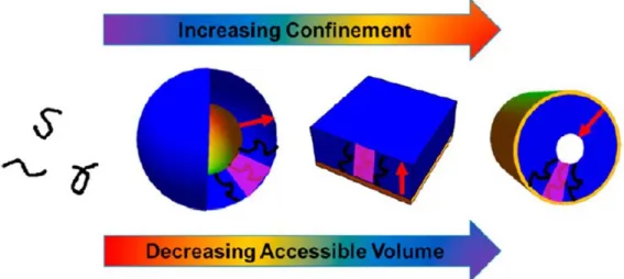
Figure 1-11. Schematic illustration of the confinement effect in SI-ATRP. ... 27
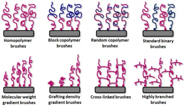
Figure 1-12. Schematic illustration of different polymer brush architectures obtained via SI-CPR. ... 36
Figure 1-13. Alexander’s model of neutral stretched brushes in a good solvent. ... 39
Figure 1-14. Schematic representation of the separate coils model. ... 41
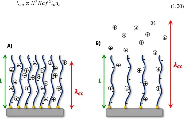
Figure 1-15. Polyacid brushes in the osmotic and Pincus regimes. ... 43
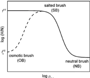
Figure 1-16. Illustration of different brush regimes for strong and weak polyelectrolytes. ... 44
Figure 1-17. Practical applications of weakly charged polymer brushes. ... 48
Figure 1-18. Schematic representation of contact angle (θ) of a droplet of liquid on solid surface. ... 52
Figure 1-19. Schematic representation of contact angle for hydrophilic and hydrophobic surfaces. ... 52
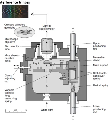
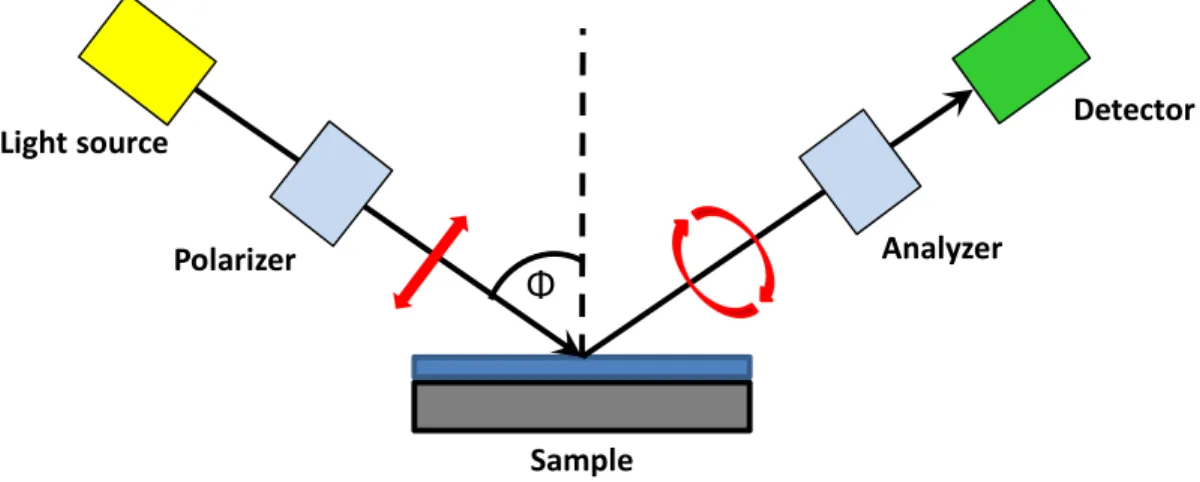
Figure 1-21. Schematic representation of set up for ellipsometry measurements. .... 58 Figure 1-22. A) Typical geometry of an ellipsometric measurement. B) Schematic
representation of p and s vector orientation in an elliptically polarized light. ... 59
Figure 1-23. Optical model for the PS-b-PAA brushes in air and MilliQ water and
the corresponding experimental data of Ψ and Δ obtained in air and liquid.. ... 66
Figure 1-24. TIR principle. A) Typical geometry incident, refrected and reflected light at the medium boundary. B) Critical angle, above which total internal reflection occurs. ... 68
Figure 2-1. AFM images of freshly cleaved mica and mica covered with initiator
layer. ... 89
Figure 2-2. AFM image showing the step-height difference between the polymer
layer of PNaA and the pristine mica. ... 89
Figure 2-3. AFM topographical micrograph of PNaA polymerized on a silicon wafer
... 91
Figure 3-1. Flow-through chamber of a silicon elastomer mounted on the glass
coverslip bearing the PMOH_PAA. ... 98
Figure 3-2. Normalized absorption and emission spectra (λex=520 nm) of immobilized PAA-PMOH on silica slides. ... 109
Figure 3-3. Time-dependent PMOH-PAA fluorescence as a function of pH with no
added NaCl.. ... 112
Figure 3-4. Time and pH dependence of PMOH-PAA degrafting at 10 mM NaCl.113 Figure 3-5. AFM images (10x10 µm) in the dry state showing the step-height
difference between the bare glass and the polymer layer. ... 114
Figure 3-6. The average PMOH-PAA polymer degrafting ratio taken as the ratio
between the polymer layer thickness after and before exposing the substrates to different pH without and with added salt.. ... 115
Figure 3-7. Fluorescence emission spectra of PM605 and PMOH in sodium dodecyl
Figure 3-S1. PAA-PMOH covered glass slide and blank silica under ambient
light. ... 119
Figure 3-S2. PAA-PMOH covered glass slide and blank silica under UV lamp
(λ=365 nm) ... 119
Figure 3-S3. Gel permeation chromatogram of poly(tert-butyl acrylate). ... 120 Figure 3-S4. AFM images in the dry state showing the step-height difference
between the native glass and the polymer functionalized surface. ... 120
Figure 4-1. Schematic representation of liquid cell used for ellipsometry
measurements. ... 132
Figure 4-2. Optical model used to calculate the thickness of swollen PAA brushes by
ellipsometry. ... 134
Figure 4-3. A) Mn of free polystyrene and PS thickness as a function of time. B) Evaluation of the free polymer PDI as a function of polymerization time. C) Polystyrene film thickness vs. molecular weight (Mn) of the free polymer in solution.
D) AFM image of polystyrene brushes grafted from silica substrate. The thickness of
the displayed sample is 10 nm. ... 138
Figure 4-4. Top-view and 3D AFM images of 1x1 µm scan size PS-b-PtBA
brushes... ... 140
Figure 4-5. Refractive index vs. wavelength for the different layers used in the model
illustrated in Figure 4-2. ... 142
Figure 4-6. PAA thickness measured by ellipsometry during first pH increase from
5.5 to 10.5 and decrease from 10.5 to 5.5, second pH increase from 5.5 to 10.5 and decrease from 5.5 to 10.5. ... 144
Figure 4-7. Variation of PAA thickness with time when alternately immersing the
sample in pH 10.5 and water. ... 145
Figure 4-8. Variation in PAA brush thickness with pH without salt or with different
Figure 4-S1. ATR-FTIR spectra of 10nm thick polystyrene brushes grafted from
silica wafer. ... 150
Figure 5-1. ATR-FTIR spectra of 5 as a powder and immobilized on silica. ... 171
Figure 2. AFM images of native silica, native mica, modified silica, and 5-modified mica. ... 173
Figure 5-3. ATR FTIR spectra of PSPMAA and PAA layers immobilized on silica substrates. ... 175
Figure 5-4. AFM images and surface topographical profiles of PAA and PSPMAA brushes grafted from 5-functionalized silica ... 176
Figure 5-5. Schematic representation of polymer brushes grafted from 6 and 5 immobilized on a silica substrate. ... 177
Figure 5-6. A) Variation of the PAA layer thickness grafted from initiator 6 at different pH without added salt. B) Variation of PAA layer thickness prepared from immobilized 5 at different pH without and with added NaCl. ... 180
Figure 5-7. Normalized force profiles measured on approaching two opposing PAA brushes across water, buffer solution pH 9.5 without salt and buffer solution pH 9.5 with salt.. ... 183
Figure 5-8. Friction force as a function of the normal force between two opposing PAA brushes measured in water, buffer solution pH 9.5 without salt and buffer solution pH 9.5 with 10mM salt.. ... 184
Figure 5-S1. Synthetic scheme for the preparation of phosphonic initiator (5). ... 187
Figure 5-S2. 1H NMR spectrum of 1, 2, 3, 4 and 5 in chloroform. ... 188
Figure 5-S3.13C NMR spectrum of 2, 3, 4 and 5 in chloroform. ... 18989
Figure 5-S4. Mass spectrum of 1. ... 1900
Figure 5-S5. Mass spectrum of 2. ... 1911
Figure 5-S6. Mass spectrum of 3. ... 192
Figure 5-S7. Mass spectrum of 4. ... 193
Figure 5-S9. High resolution mass spectrum of 5. ... 195 Figure 5-S10. High resolution mass spectra of freshly synthesized 5 (B) after 5
recycling cycles. ... 1966
Figure 5-S11. Theoretically calculated length of 5 after energy minimization. .... 1966 Figure 5-S12. PAA and PSPMAA brushes on silica. Polymer grafting reaction was
performed with the conventional (siloxane) initiator. ... 1977
Figure 5-S13. Degrafting studies of PAA brushes synthesized from 5-modified silica
List of Tables
Table 1-1. Comparison between free radical polymerization and controlled/ “living”
radical polymerization ... 16
Table 1-2. Refractive indices obtained by ellipsometry at 589.3 nm and
corresponding PAA layer thickness at different conditions. ... 66
Table 2-1. Comparison of polymer layer thickness of PNaA polymerized via ATRP
under similar polymerization conditions on mica and silica wafers………...91
Table 3- 1. Surface properties of initiator-functionalized and PAA-functionalized
silica substrates………..108
Table 4-1. Composition of PS-b-PAA brushes from different samples…………...141 Table 4-2. Refractive indices obtained by ellipsometry at 589.3 nm. ... 142 Table 4-S1. Some parameters of PtBA and PAA layers. ... 151 Table 5-1. Thickness and contact angle of water on 5-modified silica and polymer
brushes ... 170
Table 5-S1. PAA layer roughness measured under different conditions. The size of
List of Schemes
Scheme 1-1. Schematic illustration of the three main steps of radical
polymerization. ... 14
Scheme 1-2. Exchange between active and dormant species in CRP. ... 15 Scheme 1-3. Schematic illustration of formation of persistent Y• and transient R• radicals and their termination.. ... 16
Scheme 1-4. Mechanism of RAFT and NMP polymerizations. ... 17 Scheme 1-5. Schematic representation of Kharasch addition. ... 18 Scheme 1-6. Schematic representation of the ATRP mechanism. ... 19 Scheme 1-7. Schematic representation of the contributing reactions of Cu-mediated
ATRP. ... 21
Scheme 1-8. Schematic representation of SI-ATRP using Cu-based catalyst. ... 23 Scheme 1-9. Schematic representation of the “radical migration” mechanism. ... 25 Scheme 1-10. Schematic representation of ATRP in water. ... 29 Scheme 1-11. Schematic representation of possible coordination of deprotonated
PMAA with [Cu(II)L]+ complex. ... 34
Scheme 2-1. Schematic of immobilization of 1 and direct polymerization of NaA on
mica. ... 87
Scheme 3-1. Schematic representation of PMOH coupling to immobilized PAA to
afford the fluorescent polymer, PAA-PMOH. ... 106
Scheme 4-1. Synthetic route for the synthesis of PS-b-PAA brushes grafted from
silica wafer. ... 135
Scheme 5-1. Schematic representation of phosphonic acid initiator coupling to silica
Scheme 5-2. Synthetic scheme for the preparation of PAA and PSPMAA brushes
List of acronyms, abbreviations and symbols used
α average degree of ionization
αB degree of ionization of free chain in solution
βI stability constant of Cu(I) complex
βII stability constant of Cu(II) complex
Δ phase difference
Ψ amplitude ratio
ε0 vacuum permittivity
εT relative dielectric constant
λGC Gouy-Chapman length
ν excluded volume parameter
θa advancing contact angle
θobs observed contact angle
ρ polymer density
σ brush grafting density
Σ surface charge density
a size of monomer
AFM atomic force microscopy
ATR-FTIR attenuated total reflection Fourier transform infrared spectroscopy
AOI area of interest
ATRA atom transfer radical addition ATRP atom transfer radical polymerization bipy 2,2’-bipyridine cH+ proton concentration
cS salt concentration
d distance between brush anchoring points DCM dichloromethane
DMAP 4-(dimethylamino)pyridine DP degree of polymerization
e elementary charge
EDCl 1-ethyl-3-(3-dimethylaminopropyl)carbodiimide hydrochloride
f degree of ionization
f1 fraction of hydrophobic molecules grafted to the surface
f2 fraction of hydrophilic molecules grafted to the surface
F polymer chain free energy Fel elastic free energy
Fint interaction energy
Fstretch free energy of stretching
GPC gel permeation chromatography h dry polymer layer thickness H swollen polymer layer thickness
HPLC high-performance liquid chromatography HR MS high resolution mass spectrometry k extinction coefficient
kact ATRP activation rate constant
kB Boltzmann constant
kdeact dissociation constant
Kdisp ATRP deactivation rate constant
Kdisp∗ Disprosportionation constant
KD Conditional disprosportionation constant
Keq ATRP equillibrium constant
kp ATRP propagation constant
kt ATRP termination constant
KX halidophilicity
lB Bjerrum length
Mn number average molecular weight Mw mass average molecular weight
MS mass spectrometry
MSE mean-squared error
n refractive index
N degree of polymerization
NA Avogadro’s number
NaA sodium acrylate
NMP nitroxide mediated polymerization NMR nucreal magnetic resonance
p monomer conversion
PAA poly(acrylic acid)
PDI polydispersity index
PE polyelectrolyte
pKa acid dissociation constant
PM 605 8-Acetoxymethyl-2,6-diethyl-1,3,5,7-tetramethyl pyrromethenefluoroborate
PMAA poly(methacrylic acid)
PMDETA N,N,N′,N′′,N′′-pentamethyl diethylene triamine
PMOH 8-Hydroxymethyl-2,6-diethyl-1,3,5,7-tetramethylpyrromethene fluoroborate
PPTS pyridinium-p-toluene-sulfonate PS polystyrene
PS-b-PAA polystyrene-block-poly(acrylic acid) PSPMAA poly(3-sulfopropyl methacrylic acid) PtBA poly(tert-butyl acrylate)
RCE rotating compensator ellipsometer
Q brush swelling ratio
RF Flory radius
Rp rate of polymerization
rp amplitude of p orthogonal vector
rs amplitude of s orthogonal vector
RAFT reversible addition fragmentation chain transfer polymerization
RMS root mean square
s distance between two adjacent grafting points SDS sodium dodecyl sulfate
SE spectroscopic ellipsometry SFA surface forces apparatus
SPMA 3-sulfopropyl methacrylate potassuim
T temperature
Tg glass-transition temperature
tBA tert-butyl acrylate
T-BAG tethering by aggregation and growth
TFA trifluoroacetic acid
THF tetrahydrofurane
TIRFM total internal reflection fluorescence microscopy UV-vis ultraviolet-visible spectroscopy
Acknowledgements
First of all, I would like to thank my supervisors Prof. Suzanne Giasson and Prof. Will Skene for giving me this great opportunity to pursue my PhD studies in their laboratories. I am very grateful for their constant encouragement and guidance throughout my work, the possibility to attend multiple international and local conferences, and detailed reading and correction of this thesis.
I greatly acknowledge Department of Chemistry for providing me a waiver from high tuition fees for international students, as well as granting me the travel scholarship to attend 96th Canadian Chemistry Conference and Exhibition in Quebec City.
I would like to thank Centre for Self-Assembled Chemical Structures (CSACS/CRMAA) for the opportunity to share thoughts and ideas with scientists from different universities working in the same area.
I would like to acknowledge Prof. Antonella Badia, Prof. R.E. Prud’homme, and Prof. Christian Pellerin for granting me an access to their equipment. Also I want to thank our collaborators from McGill University Prof. Gonzalo Cosa and Prof. Peter Grutter as well as students from both groups Robert Godin, Wayne Mah, Matthew Rigby for their guidance and assistance with multiple techniques.
My special thanks to Patricia Moraille and Jacqueline Sanchez for introducing me the magic world of nano imaging. I am extremely grateful for their constant support with ellipsometrical and AFM experiments and, especially, for their inexhaustible humour. All time what I spent in AFM and Ellipso laboratories was a great pleasure to me.
Also I would like to acknowledge Pierre Ménard–Tremblay for his assistance and resourcefulness in GPC analysis. Moreover, I express many thanks to Prof. Christian Pellerin, Marie Richard-Lacroix, and Damien Mauran for helping me with IR experiments, interpreting results, and numerous fruitful discussions.
I am grateful to AIST NT and Andrey Kayev for the high resolution AFM images of phosphonate-modified substrates.
I would like to thank summer intern, Charly Ou, for his diligence and patience in performing ellipsometry kinetics studies.
The past and present members of the Giasson’s and Skene’s laboratories have been to me the much more than colleagues, through their scientific insights and their emotional support. Béatrice Lego, Andréanne Bolduc, Stéphane Dufresne, Dr. Yanmei Dong, Dr. Satya Barik, Sophie Bishop, Thomas Skalski, Lucie Giraud, Vivian Machado, words cannot describe my gratitude. Especially I would like to thank Andréanne and Sophie for taking care of in-time chemicals and disposables ordering, instruments maintenance and overall lab care. This made my synthetic work pleasant and effective. Also, I would like also to express my sincere thanks to the members of other groups for the good time spending together and helpful advices: Adeline Lafon, Eliza Hutter, Alexandre Moquin, Jean-Richard Bullet, Na Xue, Stéphanie Boissé, Fabien Perineau, Anna Gittsegrad.
I am thankful for the administrative support from André Beauchamp, Christian Reber, Nina Duguay-Hébert, Céline Millette, as well as technical support from Cédric Ginart, Jean-François Myre and Martin Lambert.
Thanks a lot to Maksym Kryuchkov and Iryna Perepichka for their many insightful suggestions in science and everyday life, moral support during early days in Canada and UdeM, and shared wisdom in facing the difficulties of graduate studies.
I would like to thank my dear parents Yurii and Olena Borozenko for giving me courage and determination to pursue my goals. Also I thank my sister Katia who brought me a piece of home when she decided to pursue her graduate studies in UdeM.
Finally, I am evermore grateful to my family: my husband, Vladimir, for his endless love, constant support, and absolute understanding, and to my little treasure, Eva, for giving me a new meaning of life.
Chapter 1
1.1. Polymer brushes. General concept
The term end-grafted polymers corresponds to systems where macromolecules are attached by one anchoring point to the surface (interface). During the last decades, such polymer films have served as useful platforms to develop intelligent multifunctional materials for colloidal stabilization against aggregation,1,2 for numerous biomedical3-6 and engineering7-9 applications as well as “smart” substrates having unique properties.3,10 The large variety of substrates that can be modified with polymer layers includes silica, mica, graphite, metals, carbon, cellulose, etc. The combination of polymer chains with an inorganic material opens new opportunities for contemporary material chemistry in terms of designing hierarchically-ordered structures having well-controlled morphologies and properties.3
There are three main conformations of surface end-grafted chains (Figure 1-1): pancake, mushroom, and brush. The pancake conformation is characterized by low polymer grafting density with d>>RG, where d is the distance between anchoring
points and RG is the corresponding radius of gyration of polymer chain in solution
(Figure 1-1, A). This regime is also characterized by polymer-surface attraction, resulting in spreading of the polymer chains over the substrate. Mushroom conformation is observed when the d≥2RG(Figure 1-1, B). With increasing surface
coverage, the brush conformation is adopted. In this regime d is much smaller than RG. All chains tend to stretch away from the surface because of strong repulsive
segment-segment interactions. (Figure 1-1, C).
The brush conformation exhibits particular properties because of its strong stretching. For example, polymer brushes can be used as ultra-low friction self-lubricating surfaces in artificial implants.11 “Smart” or stimuli-responsive platforms are also possible with polymer brushes by undergoing conformational changes in response to specific stimuli (pH, ionic strength, light, mechanical stress) and such responsive platforms are extensively used in biology and medicine as nanosensors.3
Figure 1-1. Conformations of end-grafted polymer chains
A) – “pancake” conformation; B) – “mushroom” conformation; C) – “brush” conformation.
This thesis focuses on the synthesis of polymer brushes and their surface properties at high grafting density. After a brief overview of different grafting methods, the synthesis of polymer brushes using controlled radical polymerization methods will be presented. A general theoretical description of different types of polymer brushes will also be given. The unique surface properties specified by higher-order interactions between adjacent polymer chains will also be reviewed and the current knowledge in the studied field will be provided.
1.2 Polymer grafting methods
Polymer grafting refers to linking (tethering) polymer chains to the substrate. Methods of polymer tethering can be divided into two major groups depending on the type of polymer interaction with the substrate: grafting by physisorption and grafting by chemisorption. Grafting by physisorption relies on physical interactions of the polymer with the substrate. This is straightforward and does not require complicated equipment. However, physisorbed films can be easily detached from the surface, and
their thermal instability leads to poor control over grafting density. Grafting by chemisorption is the covalent bonding of polymers to the substrate. This method is more complicated than physisorption and it requires precise grafting conditions and complex equipment. Chemisorbed polymer layers are more robust than physisorbed films and they show long-lasting stability. This is important for many practical applications.12-14
1.2.1 Physisorption of polymers
The physisorption of polymer involves weak interactions (electrostatic, hydrophobic, and hydrogen bonds) between the polymer chain and the substrate. Attaching the polymer to the substrate can be done using coating techniques, absorption from solution, Langmuir-Blodgett, and layer-by-layer deposition (Figure 1-2).13
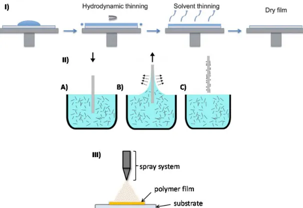
For all coating techniques (spin coating, dip coating and spray coating), the molecules are deposited by evaporating the solvent. Spin-coating is a deposition procedure where the polymer is dissolved in a volatile solvent and the solution is spun over the substrate, followed by solvent evaporation (Figure 1-2, I).15 Dip coating can be separated into several steps: immersion of the substrate into a solution, withdrawal from the coating fluid, and drying (Figure 1-2, II, A-C).16 Spray coating is done by depositing the polymer solution on a substrate by a sprayer and the film is dried under air (Figure 1-2, III). These techniques can give well-defined polymer thin films when the deposition conditions (solvent, deposition time) are controlled properly. The advantage of dip- and spin-coating is that homogeneous films of the order of few nanometers thick are possible.
Figure 1- 2. Schematic illustration of different coating processes.
I) spin-coating (Reproduced from ref. 15 with the permission of the Royal Society of Chemistry); II) dip coating process includes three steps: immersion of a substrate into the solution (A), withdrawal of the substrate (B), drying (C). (Reproduced from ref.
16 with the permission of Elsevier); and III) spray coating.*
Polymer adsorption from solution. Long polymer chains in solution can adopt numerous conformations because of entropic factors. However, the number of possible polymer conformations of a homopolymer is reduced when absorbed on a substrate. Polymer adsorption occurs when the attractive force between the polymer and the surface is higher than the conformational entropic loss.17-19 The simplest case is the adsorption of the homopolymer (Figure 1-3, A).
* It is important to mention that all these techniques can be applied for grafting by chemisorption when
Figure 1-3. A) Schematic representation of homopolymer adsorption on a flat
substrate from solution. B) Possible polymer chain conformation.
The possible polymer conformation on the surface was studied experimentally and it was confirmed with computer simulations. Figure 1-3, B shows a typical conformation of a homopolymer chain adsorbed on the substrate. This conformation is represented by a combination of tails, loops, and trains.20 Tails are the end parts of adsorbed polymer chains that extend far from the surface. Loops are groups of freely spaced adjacent monomers between two surface linked units. In contrast, trains are groups of adjacent units that are bonded to the surface.
In adsorption of diblock copolymers, the poorly-solvated block interacts with the substrate, while, the other block extends away from the surface into solution. The adsorption of diblock copolymers has also attracted much attention, particularly, because such adsorbed macromolecules can be considered as high molecular weight amphiphiles and their morphological characteristics, such as molecular weight and relative length of the blocks, determine macroscopic film properties.21,22
Layer-by-Layer (LbL) deposition. This technique is based on stacking of oppositely charged polymers (Figure 1-4). This is done by successively dipping the substrate into solutions containing interacting macromolecules. After each
deposition, the substrate is thoroughly washed to remove the weakly adsorbed molecules and to avoid cross-contamination of the solutions. The driving force for polymer adsorption is the entropic gain from releasing the counter ions. The layers are typically stabilized by electrostatic forces.23 However, there are some examples where LbL films are stabilized by hydrogen bonding, hydrophobic interactions, DNA hybridization, and covalent bonding.24
Figure 1-4. Schematic representation of layer-by-layer deposition on a flat surface.
(Reproduced from ref. 24 with the permission of Elsevier).
Langmuir-Blodgett (LB) technique. This is an elegant method for fabricating nanostructured films. It was invented by Irving Langmuir and Katherine Blodgett.25 In this method the insoluble amphiphilic polymer chains form a monolayer at air/water interface. The hydrophilic block usually stays immersed in the aqueous medium while the hydrophobic block tends to be collapsed at the air/liquid interface because of the unfavourable interaction with water. The monolayer can be transferred to a solid support either by touching the monolayer with the substrate horizontally Schaefer method) or by pulling the substrate vertically out (Langmuir-Blodgett method) (Figure 1-5).25,26 Once the monolayer is adsorbed, a thin film of accurate thickness and degree of ordering can be formed.27,28 LB polymer films,
however, suffer from limited mechanical and thermal stability. Particularly, decomposition of LB films often happens at temperature below 100oC.29 Also LB films can be destroyed under high pressure.
Figure 1-5. Schematic representation of Langmuir-Blodgett deposition.
(Reproduced with permission from ref. 13 Copyright Wiley-VCH Verlag GmbH & Co. KGaA.)
These deposition methods represent simple ways to prepare polymer-coated surfaces. However, the physisorbed polymer films have a limited range of potential applications due to the weak interactions between the substrate and polymers that results in film detachment or displacement. Polymer films can be destroyed by replacing the weakly attached polymers by strongly adsorbed polymers (adsorption-desorption exchange).30-32
Also, temperature changes cause many undesired processes with physisorbed polymers. For example, dewetting occurs when a thin polymer film is heated above its glass transition temperature (Tg), resulting in micro- or macroscopic ruptures in
the film and to morphology changes.33-35 Another process is film delamination. This usually occurs at temperature below the Tg, when the film is in a glassy state.
Delamination is caused by severe mechanical stress and also results in significant changes in film topography.24,25
Chemisorption overcomes most of the above mentioned shortcomings because of the stronger polymer-substrate bond. However, it requires more sophisticated deposition methods and equipment to accurately control the grafting conditions.1,13
1.2.2 Chemisorption of polymers
In contrast to physisorbed polymer coatings, chemisorbed layers are more robust because they are linked to the substrate via covalent bond. They can also sustain a larger variety of environmental conditions. There are three methods to get chemically attached polymer layers to the surface: grafting to (onto), grafting through and grafting from.
1.2.2.1 Grafting to method
In the grafting to method (Figure 1-6), presynthesized polymers are covalently attached to specific sites on the surface through their functional end groups. This results in end-tethered polymer chains.3 Typical end-groups that react with substrates are silanes,36-38 hydroxyls,39 thiols,40,41 amines42 and carboxylic acid groups.43 These chemical bondings are straightforward and are similar to the self-assembly.13,44 The anchor group is usually polar, and such polar or charged side groups compete with end-grafting. In this case, the attached layer consists of both physisorbed and covalently linked polymers.45,46 The main advantage of grafting to approach is that the polymer can be fully characterized prior to the grafting. This allows the polymers with low molecular weight distribution to be used in grafting, resulting in well-defined polymer brushes.
Figure 1-6. A) Schematic illustration of grafting to. B) Limitation of grafting to:
formation of steric barriers that prevent an additional attachment of polymers.
The main disadvantage of the grafting to approach is its grafting density, and consequently, its low polymer film thickness (1-5 nm).13,37 Large grafting densities are difficult to obtain because the adsorbing chains disfavour further polymer adsorption due to the steric hindrance (or excluded volume) effect (Figure 1-6, B). This effect is more pronounced when increasing the grafting density. However, the grafting density of the brushes prepared with the graft to approach can be improved either by grafting the polymer from its melt,47 or from its concentrated solution,48 or using a “theta” solvent as the grafting solvent.49 These approaches usually result in higher polymer grafting density because of the screening of the excluded volume effect.
1.2.2.2 Grafting through method
This is a straightforward technique that consists of polymerizing in the presence of a monomer-functionalized substrate.13 The substrate containing a monomer layer is added to the polymerization mixture. After polymerization, the synthesized polymers remain connected to the substrate.50,51
An example of grafting through polymerization using reversible addition-fragmentation chain-transfer (RAFT) is shown in Figure 1-7. A crosslinked layer of polycarbazole containing a methacrylate monomer was used for RAFT polymerization of methyl methacrylate and other monomers. The resulting PMMA film was varied from 9 to 22 nm in thickness.50
Figure 1-7. Schematic representation of RAFT “grafting through”. CTA refers to chain transfer agent.
(Reproduced from ref. 50 with the permission of Springer).
The grafting through has the advantage of being straightforward and utilizes controlled radical polymerizations. It is a good alternative to grafting to because it does not require synthesizing end-functionalized polymers. However, it suffers from the same disadvantages as the grafting to method, particularly, only limited grafting densities can be obtained.13
1.2.2.3 Grafting from method
Grafting from is a powerful alternative that involves the in-situ polymerization of an initiator-functionalized substrate. For this, the initiating groups
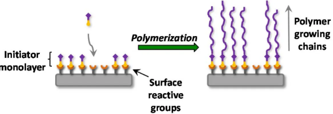
Figure 1-8. Schematic representation of “grafting from” consisting of an initiator
covalently immobilized on the surface and polymerization using a controlled polymerization technique.
In contrast to grafting to, the grafting from method produces well-defined polymer brushes of high grafting density. This is because the grafted layer is swollen by the monomer solution and monomer diffusion towards the growing chains is not
limited.53 It must be noted that the polymer molecular weight distribution of the
grafted chains is broader than in the grafting to method. This is linked to several aspects, such as polymerization side reactions, low initiator efficiency, and high
termination rate between neighbouring propagating radicals.54
The grafting from method is widely used to synthesize polymer brushes from substrates of different geometries, such as flat, curved, and linear topologies (Figure 1-9).
There are many polymerization techniques that can be used to synthesize
polymer brushes, such as anionic,55,56 cationic,57,58 ring-opening,59 ring-opening
metathesis,60 and conventional free radical polymerization.61,62 However,
controlled/“living” radical polymerization (CRP) techniques are particularly attractive to obtain polymer brushes having desired thickness, composition,
Figure 1-9. Examples of chemically attached brushes on different substrates.
1.3 CRP techniques: General overview
The precise control of polymer molecular weight, composition, and functionality is possible with controlled/ “living” radical polymerization (CRP) methods. There are three main methods of CRP: nitroxide mediated polymerization (NMP), reversible addition-fragmentation chain transfer polymerization (RAFT), and atom transfer radical polymerization (ATRP).
ATRP is the key polymerization technique that we used in the present work. We will therefore provide a brief comparison of CRP to conventional free radical polymerization. A detailed description of ATRP and its use for surface modification will follow.
1.3.1 CRP vs. conventional free radical polymerization
Understanding the principles of conventional free radical polymerization is of importance for investigation the advantages of CRP. Thus, this section focuses on comparing these two radical polymerization methods.
Conventional radical polymerization involves three main steps: initiation, propagation, and termination. The initiation forms the reactive species – radicals,
followed by their addition to the monomer. During the propagation step, the radicals react with the monomer until bimolecular coupling between two radicals occurs. This leads to the formation of a dead polymer and the active sites are irreversibly destroyed (Scheme 1-1).65
Scheme 1- 1. Schematic illustration of the three main steps of radical polymerization:
I) initiation, II) propagation, III) termination, where I is an initiator, R. is a radical, M is a monomer.
The overall kinetics can be expressed by the following equation (1.1):66
Rp=kp[M](fkd[I]o/kt)1/2 (1.1)
where Rp is a rate of polymerization, which is proportional to the initiation efficiency
(f), initiator decomposition (kd), chain propagation (kp), chain termination (kt) rate constants, and concentration of monomer ([M]).
The degree of polymerization depends on the termination and transfer rates. When the transfer is close to zero, the polymer average degree of polymerization (DPn) is proportional to the concentration of initiator ([I]) according to eq. 1.2:
DPn=kp[M](fkd[I]okt)-1/2 (1.2)
During free radical polymerization, the radical lifetime is extremely short (less than a second). Such conditions cannot assure proper control over polymer molecular weight and molecular weight distribution. Therefore, well-defined block or
graft copolymers are not readily possible. However, this control is possible with “living” polymerization that has a low termination rate.
Radical polymerization having “living” properties is called controlled radical polymerization (CRP). This approach was presented for the first time more than 35 years ago,67 but it only was employed for controlled radical polymerization. CRP has the advantage of simultaneous initiation and chain growth. A fast exchange between active and dormant species is an absolute requirement for controlled polymerization kinetics. An active species react with just a few monomers within a few milliseconds before it deactivates to the dormant state (Scheme 1-2).
Scheme 1-2. Exchange between active and dormant species in CRP, where Pn is a polymer of length n, Pn• is a polymeric radical of length n.
Some important features between conventional free radical polymerization and CRP are compared in Table 1-1.
There are three main types of CRP: RAFT, NMP and ATRP. RAFT is based on a degenerative transfer mechanism with the presence of a transfer agent, while NMP and ATRP are based on persistent radical effect. This effect relies on the formation of two species, persistent (Y•) and transient (R•) radicals, during the initiation step (Scheme 1-3, I). Transient radicals can self-terminate (Scheme 1-3, III), while persistent radicals cannot and they disappear only by cross-coupling (Scheme 1-3, II). 70-72 In NMP persistent radicals are free nitroxide species, whereas, in ATRP, it is a metal complex in a higher oxidation state.65,66,68,69
Table 1-1. Comparison between free radical polymerization and CRP
Parameter Free radical polymerization CRP
1. Initiation
Slow and continuous. Only a small initiator portion is consumed to initiate the reaction.
Fast. Instantaneous initiation and growth of all chains. 2. Growing chain
lifetime Less than a second Up to several hours 3. Polymerization
rate Fast polymerization
Relatively slow polymerization 4. Portion of dead
chains Almost all chains are dead
The part of dead chains is <10%
5. Steady state Balance between rates of initiation and termination.
Balance between rates of activation and deactivation
6. Termination
Bimolecular termination and chain transfer (chain-breaking reactions) take place between long chains and generated new chains.
No chain-breaking reactions. Because of the huge number of growing chains, only a small portion of them is terminated (1-10%), the rest of the chains are deactivated, but can be activated back. ⃰ Comparison from information provided by references13,65,66,68,69
Scheme 1-3. Schematic illustration of formation of persistent Y• and transient R• radicals and their termination.
RAFT is a Radical Addition-Fragmentation chain transfer polymerization assisted by a chain-Transfer (RAFT) agent. The polymerization is started with a conventional free radical initiator (peroxide or AIBN) decomposition that generates
I
R
.
+
R-R
R
.
+
R-Y
R
.
+
Y
.
Y
.
R
.
I)
II)
III)
the propagating radicals. The propagating radical adds to the carbon-sulfur double bond of the RAFT agent. This intermediate is further converted to another macroradical and an equilibrium between dormant and active species is established (Scheme 1-4, A).73,74
Scheme 1-4. Mechanism of RAFT (A) and NMP (B) polymerizations, where Pn• is a polymeric radical of length n, and kβ is a fragmentation rate coefficient.
The driving force in NMP is the thermal homolytic breakage of an alkoxyamine bond followed by monomer addition to the transient radical. The reactive radical can then be capped with a persistent nitroxide to form a dormant species (Scheme 1-4, B).66,75
ATRP is discussed more in details in the following sections.
1.3.2. ATRP: General concept
ATRP (Atom Transfer or transition metal catalyzed living Radical Polymerization) was introduced in 1995 by Sawamoto and Matyjaszewski independently.76,77 This polymerization method is based on atom transfer radical addition (ATRA), a well-known reaction of carbon-carbon bond formation.78 In turn, ATRA originates from the Kharasch addition reaction that was reported for the first
A)
time in 1940s. ATRA refers to a direct addition of polyhalogeneted alkane to an alkene in the presence of a free radical initiator and involves a free radical mechamism (Scheme 1-5).79,80
Scheme 1-5. Schematic representation of Kharasch addition.
ATRA is catalyzed by a metal complex. After the initial addition of the monomer to the double bond of an alkene, the obtained product is unstable and reacts with a transition metal complex irreversibly. Consequently, only one addition step occurs.81,82
The ATRP mechanism is described in Scheme 1-6. ATRP is based on the reversible oxidation of a transition metal complex (MtnLm) with transport of a halogen atom, (X), from a dormant species, (Pn-X). A dynamic equilibrium is established between the halogen-capped polymer chain and the corresponding radical (Pn•; active species) with a rate constant of activation, (kact), and deactivation, (kdeact). Propagating radicals polymerize with a propagation rate constant (kp) until it is deactivated by the Mtn+1Lm complex. The number of monomer units added during an activation cycle tends to be minimum and the kdeact is much larger than kp.83 At the
end of the polymerization reaction, all the chains are capped with a halogen through reversible halogen exchange reaction. Those can then be used as macroinitiators for further ATRP reactions.
Shifting the equilibrium towards the dormant species and fast switching between the activation-deactivation states assures a low concentration of active species and, consequently, good control over the polymerization. As it has been shown by means of electron paramagnetic resonance (EPR), the concentration of deactivator (that relates to the concentration of active propagating species) does not
exceed 6% for a well-controlled system. Adding small portions of deactivator at the beginning of the polymerization can improve the general polymerization control. The role of deactivator in this case shifts the equilibrium towards the dormant species and improves the overall reaction control. Usually about 10% of deactivator is added, corresponding to the deactivator quantity that is generated during polymerization due to irreversible deactivation.87 Termination reactions can also occur with a rate constant of termination (kt). However, in well-controlled ATRP, only a few percent (≤5%) of growing polymer chains are subjected to termination.88 The termination reactions usually occur during the initial step when the concentration of deactivator (as persistent radicals) has not reached yet the optimum.71,88
Scheme 1-6. Schematic representation of the ATRP mechanism.
A key component of ATRP is the transition metal complex catalyst.69,88 The ideal transition metal has two oxidation states that differ by one electron and it must be able to accommodate the halogen atom within the coordination sphere. Suitable metals that satisfy these criteria are iron, ruthenium, nickel, and palladium. However, the most extensively used catalysts for ATRP are copper salts because of their low cost and exceptional versatility. The nitrogen- and phosphorus-based ligands play a vital role in solubilizing the transition metal salt in organic media and they adjust the redox potentials of the transition metal. For copper-mediated reactions, nitrogen-based ligands are the most appropriate. 65,66,68,88 Figure 1-10 shows some examples of generally used ligands and initiators for ATRP.
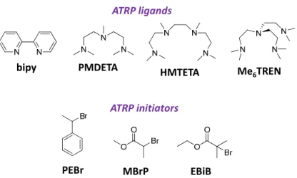
Figure 1-10. Examples of commonly used ligands and initiators in ATRP.
Ligands (from left to right): 2,2’-bipyridine (bipy), N,N,N′,N′′,N′′-pentamethyl diethylenetriamine (PMDETA), 1,1,4,7,10,10-hexamethyl triethylenetetramine
(HMTETA), tris[2-(dimethylamino)ethyl]amine (Me6TREN); Initiators (from left to right): 1-phenyl ethylbromide (PEBr), methyl
2-bromopropionate (MBrP), Ethyl 2-bromo-2-methylpropionate (EBiB)
The role of the initiator is to define the number of propagating polymer chains. The initiator structure determines the activation rate, which should equal the propagation rate for well-controlled reactions. Alkyl halides (R-X) are typically used as initiators in ATRP, where the halide group (X) and alkyl radical (R) are carefully chosen, depending on the catalyst/ligand system. The most active initiator is α-bromophenylacetate because of the active benzyl and ester moieties.89 Initiators containing multiple halide groups can also be used, resulting in the synthesis of complex architectures.
1.3.2.1.
ATRP equilibrium and kinetic aspects
Understanding the impact of kinetic parameters on “living” polymerization is of importance for the synthesis of polymeric materials having defined characteristics. The overall ARTP equilibrium can be separated into four contributing reversible
ATRP ligands
bipy PMDETA HMTETA Me
6TREN
ATRP initiators
reactions (Scheme 1-7). ATRP follows first-order kinetics for monomer, initiator and metal complex in its lower oxidation state, and negative first-order kinetics for metal complex in its higher oxidation state. The rate of polymerization, (Rp), is expressed
by the following equation (1.3), where kp is a propagation constant rate, [M] is a
concentration of monomer, [P•] is a concentration of polymeric radical, [PX] is a concentration of polymer, [XMtn+1Lm] is a concentration of deactivator, [MtnLm] is a concentration of activator , and Keq the overall equilibrium constant:
(1.3) The overall equilibrium constant, (Keq), is defined by equation 1.4, where kact and
kdeact are activation and deactivation rate constants, respectively. Both constants, kact
and kdeact, are strongly influenced by the structure of the ligand, monomer, and
environmental conditions. Thus, all these parameters are highly important for polymerization control.68,82,83
Scheme 1-7. Schematic representation of the contributing reactions of Cu-mediated
ATRP.
(1.4) The synthesis of polymers having controlled architectures requires controlling the degree of polymerization (DP) and polydispersity index (PDI). The degree of
polymerization is determined by the initial concentration of initiator, ([I]), and conversion, (p) according to eq. 1.5:
(1.5) The molecular weight distribution in well-controlled systems typically is less than 1.1.88 Equation 1.6 shows how the PDI is affected by concentration of the deactivator [XMtn+1Lm], monomer conversion and kp/kdeact ratio.90
(1.6) It can be concluded that the presence of the catalyst, which deactivates the growing chain faster, will result in a smaller kp and kdeact ratio and, consequently, a polymer
with a narrow PDI will be obtained.88 Also, the PDI can be easily decreased by increasing the deactivator concentration or by pushing the polymerization to high conversions. Equation 1.6 shows the ideal situation where no chain termination and transport occur. However, in reality, the termination and transfer occur. They can be limited by lowering the degree of polymerization.89,90 Accomplishing these requirements results in well-defined polymers having narrow molecular weight distribution.
1.4. Surface-Initiated ATRP (SI-ATRP)
In general, ATRP is the most versatile and robust polymerization technique for modifying surfaces. The first example of polymer brush synthesis via SI-ATRP was reported in 1997 by Huang and Wirth, where they successfully polymerized acrylamide from the benzyl chloride monolayer on silica particles.91
The key to SI-ATRP is the polymerization of a surface-attached initiator monolayer. This results in an end-tethered polymer layer. SI polymerization is based
on the same kinetic principles and rules as solution polymerization. Scheme 1-8 shows a typical ATRP from an initiator-functionalized flat surface.92
Scheme 1-8. Schematic representation of SI-ATRP using Cu-based catalyst.
(Reproduced from ref. 64 with the permission of Springer).
The first step is the attachment of the initiator (2-(4-chlorosulfonylphenyl) ethyltriethoxysilane, (CTS), to silica via a covalent Sisurf-O-Siinit bond. The Cu(I)X/L complex is transformed into a higher oxidation state (Cu(II)X2/L) by a halogen transition (activation). This results in a free radical at the end of the polymer chain, which reacts with monomers (propagation) until it is capped with the halogen (deactivation). The activation-deactivation occurs repeatedly and results in the simultaneous growth of surface-attached chains.
1.4.1. SI-ATRP characteristics
In spite of identical mechanism and general kinetic similarities between SI and solution ATRP, there are specific features of SI-ATRP that must be reviewed.
1. The properties of the polymer film can be tuned by the initiator grafting density. This requires proper control over the initiator grafting process.
There are several ways to do this. The most common way is varying the concentration of deposited initiator molecules and/or the coupling time.93 It can also be done by grafting a mixture of active and inactive (“dummy”) initiators in different ratios.94 Alternatively, a portion of grafted initiator can be destroyed under radiation exposure (post-grafting treatment).95 These approaches assure the proper number of initiator molecules to be attached to the substrate that, in turn, results in desired polymer brush characteristics (thickness, molecular weight, architecture). 2. Low concentration of surface-attached initiator on flat surfaces causes
slow generation of deactivating species. This results in extremely low deactivator concentration and, consequently, high probability of termination reactions. To overcome this, a deactivator or sacrificial initiator has to be added to the polymerization solution (see section 1.4.2 for details).
3. SI-ATRP is characterized by a limited rate of propagation due to the unavoidable hindered monomer and catalyst diffusion to the growing chain ends.96 This affects the polymerization kinetics and results in lower molecular weight of grafts compared to free chains. However, the opposite trend of larger Mn of grafts than free chains was also reported
(see section 1.2.3 for details).
4. Termination. As it was shown by Gao et al. for flat surfaces, the radical centers are distributed quite sparsely over the attached chains, even at high grafting density. The bimolecular termination is impossible when two radicals are separated by more than 1000 nm. However, termination takes place when the chain is activated in close proximity to the existing radical. Two radicals come together via activation-deactivation exchange with the catalyst in solution. This mechanism is called “migration-termination”97 or “radical migration” (Scheme 1-9).98