7^
(nor.,
J;r
4
C;ÿ^;,,
tSso,
Ë4,-,À.
Oy'l
ProJect No.2474
ARCHITECTURE OF A
MULTIMODAL
DIALOGUE INTERFACE FOR KNOIVLEDGE-BASED §YSTEMS.J-L. Binot,
BiM,
Everberg Belgium,P. Falzorq INRIA5 Voluceau - Rocquencourt, France
R. Perez, ISS, Barcelona, Spain
B. Peroche, Ecole des Mines, SainrEtienne, France
N. Sheehy, Universiÿ of [,eeds,
UK
J. Rouault, CzuSS, Grenoble, France
M. Wilson, Rutheford-Appleton laboratory, Chilton,
UK
ABSTRACT.
This
paper describes the architecture and thefirst
implementation resultsof
amultimodal dialogue interface for knowledge based systems developed in the context of Esprit
II
project MMI2. The paper reviews the basic principles
of
the architectureof
the system and theapproach taken by the project with respect to user modeling issues, then describes individually each
communication mode.
1. Overvlew of aims and basic approach
This paper outlines the first results of ESPRIT
II
project P2474:"MM2:
A Multi Mode Interfacefor Man Machine Interaction with knowledge based systems." These results were obtained through
the cooperative efforts
of all
researchers involvedin
the project: Jean-L,ouisBinot,
FabienneBalfroid, Lieve Debille, David Sedlock and Bart Vandecapelle
(Bllvt
Belgium), Gerard Henneron,Genevievre
kllich-Boidin,
Rosalma Palermiti, Jacques Rouault, Jean-Louis Zinger (CRISS, France), Helmi Ben Hamara, Christian Bertin, Christine Jouve, Dominique Michelucci, Bernard Peroche (Ecole des Mines de Saint-Etienne, France), Bernadette Cahour, Francoise Darse, Piene Falzon(INRIÀ
France), Alica. Manzanera, A. Moneta, Ricardo Perez, David Trotzig, Juan-CarlosRuiz (lSS, Spain), Farah Arshad, N. Ghali, Mark Howes, K. Marida, Noel Sheehy (Univ. IÆeds,
U.K.), Helen Chappel, Graham Doe, Gordon Ringland, and Michael Wilson (Rutheford Appleton laboratory, U.K.).
A multimodal system. The MMI2 project aims to build a marL/machine interface for different kinds
of users, integrating several modes of communication supported by modern workstations: natural
language, command language, graphic and gesture. The interface
will
provide simultaneously modes suitable to support the efficiency of experienced, professional users (command languages,menus) and natural communication modes well suited to naive users, such as graphics and natural
language. Natural language modules are being developed for English, French and Spnish.
Difference between modes and media.
It
seems first necessary to clarify the distinction that we make between the meanings of the trvo words medium and mode. A number of projects have alreadystudied multi-media phenomena and in particular multi-media interfaces. The multi-media concept
is present as soon as a cômputer system can deal with more than one type of input/output support.
Multi-media communication, however, does not imply multi modal communication.
lVhile a medium is only an information support, a mode is a rneans of expression and thus a meâns
to convey information: a mode is built on a lexicon, synlax, semantics etc. C-ommunication with a
computer through graphic mode requires not only a graphic medium but the definition of one or several graphic modes using that graphic medium.
Dialogue management. Advances are aimed at in each mode separately" However the main sowûe
of improvements to interface technology
will
come from the integration of the different modes. Toreach such an integration, one of the main aims of the project is to develop a dialogue managem€nt
and mode selection system
which
uses knowledgeof
the specificitiesof
individual mo&s, knowledgeof
the contextof
previous interactions, and knowledgeof
the application domain tointerpret the input, determine the content of system output and select the most appropriate mode in which
to
present particular inforrnation.A
user modeling modulewill
interactwith
dialogue management, so that the systemwill
react appropriately to different classes of users and individualusers.
Knowledge-based backend application. On the machine side, the interface is primarily aimed to
be connected to applications such as Prolog based expert systems (although $e expect many of the
results
of
this project should be usable, at least indirectly,for
many other kindsof
workstationapplication software). In order to focus on real practical problems, the interface prototype is being
connected to a specific application, also developed within this project. This application, câlled
NEST, is an expert system in computer network design. Such a system, besides having a very high
intrinsic interest
in
its own right, given the current trends in information technologÿ, has a geat varietyof
potential users and offers many opportuniliesfor
multimodal interaction, includingnatural language and graphics.
Finally, the interface is designed to be portable across a range of potential applications of Prolog
based KB.S. Special emphasis is put on designing a flexible and portable architecture having well defined interconnection points with the application and on developing a set of tools for the rapid
adaptation of the interface to a new application.
2. Architecture of the
MMI2
systemA
significant partof
the work done in the first yearof
the project has been concerned with thedefinition
of
a clear, modular and concepfually sound architecturefor
the whole system. Thearchitecture of the system is based on the notion of "expert module". The name "expert" should be
clearly understood. 'We are not proposing an architecture
of
"cooperating experts", or "multiple agen8", which, we believe, fall outside the scope of this project. V/hat we call an expert is simplya module performing specific tasks and with its own private data structures, and which represens a
sufficiently coherent set of processes to be gathered
in
a single module. While such a notion isclearly not new, the identification of the nature of the basic modules constituting the multimodal
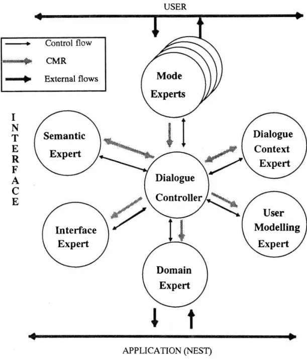
interface, and of the interactions between them, has been a crucial step in the project. The resulting architecture is illustrated in figure L below.
flow
==+
CMR
Externalflows
USER{1
a h z&
TN
T
E
R
F
A
C
E
User
Modelling
Expert
lnterface
Expert
Semantic
Expert
Dialogue
Context
Expert
Dialogue
Controller
Domain
Expert
Mode
Experts
APPLICATION
(NEST)Figure 1: General architecture of the
MMI2
systemThe basic idea of this architecture is that every input should be cast into some suitable meaning represenlation, then forwarded to the dialogue controller, which
will
decide what to do with it Thisshould hold not only for input in natural language mode, but also for inputs in command andlor
but go through the dialogue controller). The dialogue controller
will
call the dialogue contexl rnanagerto
updatethe
dialogue model accordingto
the new
interaction, then reason (oncommunication acts, inpul content, state of dialogue and user models) to decide what to do wilh the
input, how to gather resul8, what answers to present and in which output mode to present them.
To make such an architecfure possible, there has to be a meaning representation formalism
common to all modes, which is used as a vehicle for internal communicaüon of the semantic content
of
interactions inside the interface itself and also used as a support for semantic and pragmatic reasoning. This meaning representation formalism is called the CMR andwill
discussed in more details in a later s€ction.The main functionality of each of these expert modules can be described as follows:
The dialogue controller deals with:
- choosing and managing the structure of the dialogue
- performing response determination and output made selection
- activating whatever experts are necessary to support dialogue interaction
The dialogue conturt mantager manages everything which has to do with:
- identifying the dialogue structure and its various components
- recording thât structure
- extracting relevanl information from
it
a a a a t a
The zser modeling expert maintains and exploits the user model. The domain expert has all the expertise about the domain, including:
- what is covered by the domain
- how to translate the internâl meaning representation into domain terms - how to manage "task plans" describing problems to be transmitted to
the application.
The interface expeft has the knowledge about the interface
itselt
including- fea tures/capabi li tiesiconfi guration of the interface - current physical interface layout on the screen
.
The semantic expert has all the knowledge about the general (domain-independent) propertiesof meaning concepts, and of semantic inferences that can be performed on them.
The various mode experts perform input and output for each mode.
The modules being part of what is generally called the "dialogue management" process are the
dialogue controller, dialogue context manager, semantic expert and domain experl. The following
sections discuss further some basic aspects of the main modules enumerated above. But, in order to
provide a practical context, we first start iliith some words about the application chosen as a testbed
3. Testbed appllcation: an expert system in computer networh design
The application chosen for MMI2 and developed within the project is an expert system for Network Design.
It
has been chosen for its own interest and for its interest in lhe context of a rnulti-modeinterface development.
Indeed, information technology is evolving fast toward distributed systems. Configuring computer
networks is, in this context, a crucial and difficult task both from economical and technical poirts
of
view. The developmentof
expert system tools assisting such a task cân c€rtainly contribute significantly to the progressof
European information technology. On the other hand, an expert system such as the one considered here has a great variety of users: technicians and commercials,beginners and
exprts.
It
dealswith
graphic and text information and must allow request andupdating of data. So it supposes at least natural language, command language, graphics and gesture use. Thereby, it constitutes a credible praclical test for a multi-modal interface.
Different components are involved in a design system. \fo'e decided to start the development of the
application by the analysis component. This component is cunently implemented. It analyzes local area networl<s using Etherne, technology and checks
if
those networks are correct or satisfying according to differert evaluation criteria such as technological validity, extensibility, clicnt-server relatioq departmentalization or cosr. Networks which have to be analyzed are described by usingan object oriented model defined in BiM_Probe, an object oriented tool built on top of BIM_Prolog.
The next step of the application
will
be devoted to the devek:pment of the configurated component able to compute a local area network configuration respecting some given constraints such as thosespecified
by
the customer (budget, building limitations,...)or
the technological ones already considered in the analysis tool.4. Mode lntegration and dialogue context management
The MMi2 architecture is based on the fundamental assumption that
mode integration should mainly be achieved by an integrated management of a
single, generalized, discource contexL
The basic idea is that any interaction, or any "discourse" between the user and the interface, in any
of
the modes, takes placein
a
common "discourseworld"
(which may butis
not necessarilyconnected
to
the real world,or
to
an application).Any
entity mentionedin
the courseof
aninteraction acquires, by the sole virtue
of
having been mentioned, an existencein
this discourseworld, where it shall be called a "discourse referent".
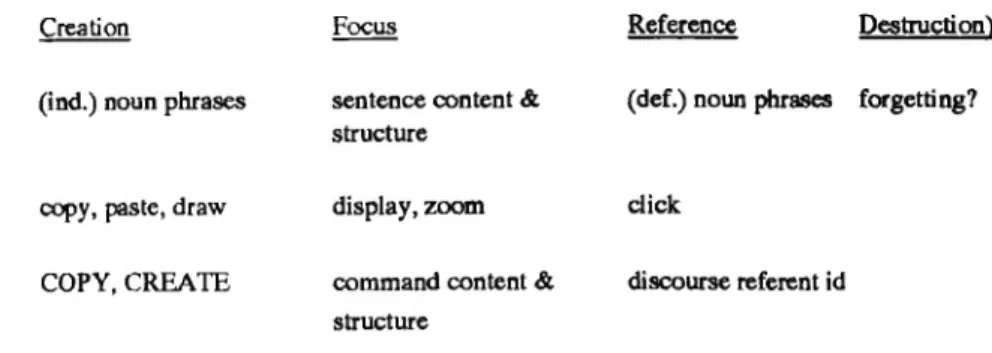
Various operations may apply to discourse referents. They may be "introduced" (or "created", or "brought into the discourse"), referred to by using a "description" of a referent, and even possibly
"forgotten" ("deleted"). They may also be brought in or out of focus, and different sorts of foci can
possibly be distinguished.
These notions are familiar to people involved in Natural l:nguage Processing. What we argue is
integration. Iæt us give a few examples about each of the mode'
In
notaral language, new discourse referents areÿpically
iûtroduced by indefinite noun phrases and refened to by definite noun phrases (many special cases can be found in the literature, butwill
not be discussed here). Thus, in
Add a server to the network Connect this server to.
the indefinite expression "a server"
will
cause the introduction of a new discourse referent in thediscourse world, and this referent
will
receive a unique identifier. The expression "this server" can then refer to the newly introduced discourse referent, and can possibly bring it into focus.For NL interaction, the referencing operation is done mainly through the use of descriptions which
take the form of (definite) noun phrases. The basic problem is to relate such descriptions to unique referent identifiers: this process is usually known as "noun phrase resolution".
In the graphical or gesture mode, any basic graphical operation
will
have an effect on discoursereferene. Creating a graphical object
will
obviously introduce a netü/ referent. Selecting an objectwith the mouse
will
perform a reference to a existing referent. Moving a graphical objectwill
bringthe
conesponding discourse referentinto
focus. Changingthe
graphical display (zooming,displaying another network, selecting another window where something else is displayed) would bring a different set of discourse referents into focus.
For the graphical mode the referencing operation is done by selection: the referent has a graphical description (as it could have one or several NL descriptions) and selecting the graphical description
leads to the identification of the referent. The problem of identifÿng the referent selected is trivial,
as each graphical object should have as associated property the unique identifier of the referent
it
represents. This association is easy to maintain: when a graphical object is created,
it
is either todisplay an existing referent (in which case the referent identifier is known) or to create a new one,
in which case a new referent identifier name should be created automatically by the system.
In
the command language mode, finally, basic operations on discourse referents âre easy toidentify, and bear close similitude to graphical ones. Thus a command to add an object
will
creale adiscourse referent for that object; commands performed on objects
will
tend to bring these objecs into focus. Reference to existing discourse referents can be done by using the unique identifier of areferent as parameter
in
a command. The referencing operationfor
command languageis
alsosimple, as the referent identifier itself can serve as description of the referent.
Reasoning
in
termsof
discourse referents and focus provides already for very interesting modeintegration, which goes further than the more or less traditional graphical deixis (simply selecting something with the mouse and asking "what is this"). Thus in a sequence like:
System:
User (NL)
System:
<Graphical act to displry nsat network> What is the server?
<Graphfual act to display an icon>
the first (graphical) utterance
will
bring a ne'ÿÿ set of discourse referent into focus. The NL querycurrent focus. The response determination module of the dialogue controller would then decide
of
a mode (graphics) and an appropriate graphical "communication act" (highlighting) to provide the ân§wer.
lVe are thus led
to
study the conditions governing creation, focusing, reference and possiblydestruction of discourse referents across all communication modes. A first attsmpt to organize the
factors controlling these events is indicated in the figure below.
NL iaput
Gtryhics
Command
Creation Focus
(ind.) noun
phrases
sentence æntent & structuredisplay, zoort
command conûent &
structure
Reference
Dcstuction) (def.) noun ptuases fugettiag?click
discourse refereot id
cçy, paste, draw COPY, CREATE
Figure 2: Operations on discourse referents across modes
5. Representing interactions - the Common Meaning Representation
A
second sourceof
integration arisesfrom
thefact
that many interactions can be expressedequivalently (from the point of view of meaning,
if
not of ease of expression) in several modeq as the following examples illustrate:NL:
Graphics:
NL:
Graphics:
Suppress the SUN3 connected to server Ella <Click on icon and select dclete opti.on> Augment Wrformance of Ella by 100Vo
<klect
appropriate bar in a bar chan about computer performance andmodifyit>
NL:
Suppress the blue servers (on color screen)Graphics:
<Click on icons and select delete option>Although expressed quite differently, all these input must have the same effect on the application
(knowledge-based system) and on the dialogue context. Thus one
of
the resultsof MMI2
is toestablish a taxonomy of actions across modes (e.g. the verb "suppress", a DELETE option in a
menu, a DELETE command or a gesture of crossing out something with the mouse all refer to a
"deleting" operation). But integrating the representation of interactions across modes can go further
than that. A second basic architectural principle of MMI2 is that
therre is a meaning representation formalism, common to all modeq whlch is used as a vehicle
for
internal communication of the semantic content of interactions inside the interface itself and also used as a support for semantic and pragmatic reasoning.This meaning repre,sentation formalism is called the CMR. The purpose of the CMR is to represent
the meaning of interactions between system and user, or user and system. Such interactions are
called "communication actions".
In
MMI2 a
communication actionis a
graphical action, acommand language/gesture action, or a natural language action, which can be canied out by either
the user or the system. lVhen the communication action is expressed in a natural language, the action is an utterance.
The proposition expressed
by a
communication action consislsof
content and logical form.Following many other practical natural language processing systems, we have chosen to express the
propositional content of a communication action in a language based on a first order ÿped predicate Iogic where relations are, as a general rule, reified. Specialized languages, such as frame or semantic
network languages, fall short of the expressive power we expect to find used in our application. (See
Chapter 2 in [Genesereth 1987]. Of course, There are extensions of these specialized languages, but
these extensions end up looking like predicate logic.) On the other hand, we do not expect to need the extra expressive power that a second order language affords.
Our approach to representing meaning can thus be regarded as logical. However, we recognize that
there are aspects to communication that are difficult, perhap impossible, to capture on a purely
logical approach. Therefore, we have decided to include extra information
in
CMR concerningillocutionary force, enunciation conditions and other things that we call "annotations". So a CMR
expression contains four sorts
of
information: illocutionary force, propositional content, logical form, and various other annotations.A
CMR expression is also part of a larger data structure thatpossibly includes the following additional information: processing status, mode, time of action, user
presuppositions, user mistakes, and some syntactic information. The following figure illustrates one
example of CMR representation. Although we shall not describe
it
in more details here, the fuil specification of the CMR language has been completed and is one of the major results of the f,rrstyear of the project.
User input:
Wat
da the machines on the nefiryork cosl?cMR( ICMR_exp(
Irequest,referent( [var(x 1 )])1,
[anno(x3,
[definitejlural
])1, (desc(the,x2, MACHINE,(desc(the,x3, NETWOR§ true), (desc(some,x4,I S_ON, true), and(
Ipred(SUBJECT, [var(x4),va(x2)]),
pred(LOC, [var(x4),var(x3)DD»), (desc(null,x 1, QUANTITY,tTUe),
(desc(some,x5, HAS_COST, true), and(
[pred(PRESENT, [var(xS)]),
pred(S UBJECT,[var(xS), var(x2) ]),
pred(OBJECT, [var(xS),va(x t)]) l)))))1,
ok,
time( 1., 1., L, 1, 1, 1990),
none, none,
none)
Figure 3: Example of a CMR representation
A series of communication actions forms a
"dialoÿ'.
CMR is not meant to be a representation of adialog although it is supposed to lend itself to the comtruction of dialog representations. Of course,
how you detine actions or utterances is not so clear in general. In practice, however, each action is
individuated by an illocutionary force: one force, one action, one thing to be represented in a CMR
expression.
6. Dialogue
flexibility
and dialogue controlThe application, being a knowledge-based system, has its own data and knowledge structures.
A
typical knowledge-based system has usually
a
"problem space", where theinitial
dataof
theproblem
to
be solved are placed, a "solution spâc€", where the expert system would build iB solution, and a knowledge base containing general knowledge and expertise about the domain.'What,
then, should happen when the user strarts to specify a problem?
Typically, for an expert system, the specifTcation of the problem may require a set of information of different types.
If
the dialogue is application-driven, these informationwill
presumably be asked tothe user in some systematic order. But, in a real problem acquisition dialogue, the user may shift topics, answer questions by other questions, proüde ambiguous or incomplete answers that
will
require subdialogues, request help, or even change his mind. It is obviously the job of the interface, and not of the application, to deal with such problems.
If
the user-provided daa were sent directly to the application, they might well be in the wrong order or proüde wrong values that would have to be corrected later. We have thus decided that for reasons offlexibiliÿ,
there should be a levelof
representation of the problem in the interface itself.
This kind
of
problem has started 10 interest researchers in dialogue management, and has beendiscussed notably
by
[Julien andall
89], who illustrateit
with an example taken from financialadvising expert systems:
SYSTEM:
How much d.o you want to invest in an emergency planU§EÀ;
Let us talk about tny car loan instead!In the face of such an answer, the interface must either enforce a strict dialogue schema, or accept a
shifting of topic, which supposes that it should be able to detect it, and to remember to come back later to the "emergency plan" topic
if
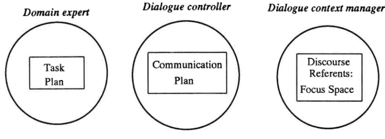
this one is essential for the formulation of the problem.To implement this kind of behavior, we decided to provide lhe interface with three basic kinds
of
data structures, a "task plan", and a "communication plan", and a "discourse referent space", the two first being inspired from [Julien and all 89]. The position of these structures in the architecture is
Task Plan
Communication Plan illustrated in figure 4 below:.
Domain
expertDialogue
controller
Dialogue
contexînunager
Figure 4: Key structures to support interaction
with
userThe basic role of the space of discourse referents has been described before.
The task plan is a model of the kind of information that need to be provided to the application in
order to specify a well-formed problem. It can be seen âs a kind of "skeleton" of a ÿpical application problem, which
will
be progressively instântiated in the course of the dialogue. Task plans areof
course domain dependent, and are thus managed by the domain expert. Several task plans may be
available for a single domain, corresponding to the different kinds of problems one can submit to
the application. The task plans
will
haveto
be provided as partof
the application dependentinformation and
will
be storedin
some partof
the domain model. Normally, the task plan to beapplied should be identified through interaction with the user.
The communication plan is a plan structure for guiding a dialogue with the user. Once â task plan is identified, there
will
be a communication plan activat€d to acquire the information necessary forthe task plan. There will be at least a communication plan for every task plan available in the cunent domain; but the selection of such communication plans
will
also depend on the user model. Therecan also be communication plans for other parts or subparts of the dialogue; for example there could be one
for
greeting the userand
ascefiainingthe kind
of
problem he wantsto
solve. As communication plans have to do with controlling the structure of the dialogue, theywill
be storedin the dialogue controller, in a "communication plan library". At any time there
will
be one activecommunication plan, which
will
be executed, andif
needed updated by the dialogue controller.7. User modeling
7.1. THE USER MODEUNG EXPERT
In MMI2, the role of the user modelling module is to increase the cooperativity of the system. The user modelling expert builds up and mainlains the user model. The user model is the knowledge
Discourse Referents: Focus Space
source in the system that contains explicit assumptions on all aspects of the user that may be relevant
t the behavior of the system. User models
will
be stored bet'r/een sessions as User Profiles whichwill
be downloaded for experienced user at logon.The major uses of the information in the user model are for:
.
The Dialogue C-ontext Expert to identify speech acE, ellipsis and other pragmaüc featureson the basis of the user's goal and beliefs.
.
The Mode Experts to present information using the symbols, lexical items and style the userprefers.
.
The Dialogue Controller, to use the user's current goal to identify the usêr's current plan and thus provide co-operative responses. Responseswill
also be tailored on the basis of theuser's beliefs according to Grice's maxims [Grice 1975] to avoid redundancy and to
empha-size and explain the user's misconceptions.
.
The Domain Expertwill
use items of user specific information in completing domain planswhich
will
form queries to the knowledge based system.The basic framework of the user modelling component comes from General User Modelling System
- GUMS - of Finin and Drager [Finin and Drager 1986]. This provides four €ssential features of the user model itself:
.
An interface between the user model and the rest of the system;.
A
mechanism for overridable default inheritance from stereotypes with opüonal negationas failure;
'
A
truth maintenance mechanism to manage the updating of inheritance from differentsu-perordinate classes during a session as the user's membership of a class changes;
.
A mechanism for storing user and class models between sessions.Two advances on the GUMS model are required fro the underlying framework of the user modelling
component in the
MMi2
architecture.Fintly,
the GUMS model only supports inheritance from a single stereotype which is limiting since users could be both a member or a class with kaowledge about the domain, and another with knowledge about the interface and system itself. InheriAnce from multiple stereotypes has been added to the GUMS system. Multiple inheritance brings *'ithit
the possibility
of
conflicts between informationin
different stereotypes. These are handled by searching for certain information râther than just default values;if
these conflict then the certaininformation overrides the default. Similarly, where negation as failure is used to show the lack
of
knowledge or belief, and knowledge or belief is stated, then the presence of knowledge or belief is
returned.
If
certainbut
contradictory knowledgeis
statedin
different places,â
tômporaryunsatisfactory heuristic is applied thât the first version encountered in the bottom up breadth first
search is returned. The second change follows from the use of multiple stereotypes. Sparc Jones
[1987] succinctly the problems
with
assuming that the userof
the system whois
entering thecommands is actually the user of the system for both the interface and the reasoning components
of
the system. Her potent example is one of a social welfare worker entering information on behalf
of
a client where the view of the user act as a filter on the information obtained about the client; eitherapproving or otherwise. The overcome this complexity, the leaf node
of
the user modelin
thepresent system represents the combination
of
the user and the client. Therefore this user model inherits from both the user and the client nodes in the lattice, each in turn from other stereotypically defined nodes.A
major requirement of the MMI2 system is to produce co-operative responses for the user. Theclass of co-operative responses expected follows IKaplan 1983, Allen 1ff]3, Carberry L985, Pollack
1986]. Their generation require representations of the user's goals; the plans for achieving them; the
user's beliefs; an evaluation of whether they are correct knowledge of misconceptions with respect
to the systems view of the world which is assumed to be rue; some decision relevant information to
be used in task plans for the KBS application; and various âttitudes and preferences of the user for
explanation style, lexical item choice, and interface style and options.
The user's beliefs are stored in the prototypes and the user's own model. These can be acquired
explicitly or implicitly as suggested above. The rules for implicitly acquiring user beliefs follow
those used by Kass [].988, 1989]. In order to use user beliefs üo interpret input to the interface or to
tailor output for the user it is useful to identify the beliefs as true to the world, and therefore user
knowledge, or false in the world, and therefore misconceptions. The test of truth in the world is
made by comparing the user's beliefs with the representâtions in the other experts and change their
status if a judgment can be made.
If
no cornparison is possible, the beliefs remain belieB and are not classified as knowledge or misconception.7.2. USER MODELING EXPERIMENTS
The set of classes and rules for determining
if
users belong to them, along with the sets of possible relevant goals, preferences, decision relevant information, knowledge and beliefs which must beincluded
in
this architecture are established for the demonstration application by the experiment described below.The experiment included two steps: simulation
of
interactions between users and a system, andpostverbalization supported by a record of the acüvity.
One expert simulated the system and different types of subjects (or 'users') requested his advice to
solve two problems of physical network design that had been previously defined in collaboration with the expert: the first problem consists of designing a network for a research department and the second one consists in designing a network connecting different buildings in a university. According to the expert these problems are typical and
of
average difficulty. The 10 subjects differed incomputer education and in type and level of knowledge about network design.
The expert used MUSK as a tool for interaction between the subjects and the expert. MUSK is a
program (designed at Rutherford Appleton I-aboratory) that allows both graphic and written
interaction befween several users simultaneously. Each of the ten subjecs solved the two problenrs
successively in the same order, the interaction for each problem taking about two hours. Every ten
minutes the expert was given evaluation sheets on which he quickly noted the user's level and type
of competence (on-line evaluation).
The second phase of the experiment consisted of a post-verbalization supported by the transcript
of
the dialogues: the expert was brought to look at the transcriptions
of
the interactions (text andgraphics) and comment on them line by line, the on-line evaluations constituting further support for
his
commenls. The aimof
this
methodis to
re-create the consullation situation theexprt
participated in. The expert's comments were focused on interlocutor modelling: he was asked to point out he clues he used for elaborating the model of the interlocutor and to stress the effecs
of
check the reliability of the evaluations.
Gathering dialogues and having the expert commenting on them have proven to be very beneficial.
This method yields rich information concerning the modelling process to be gathered [Cahour
1989]. For MMI2, the analysis of these protocols allows:
.
the specification of the content of the user rnodel, i.e. the predicates aad arguments that must be included, the stereotypes that categorize the different users and the inference rules thattrigger them.
'
the description of the elaboration of the UM, i.e. the clues in the discourse or in the drawingsof the "user" on which the expert bases his elaboration of the UM.
.
the identification of various effects of the modelling on the interactio4 i.e. the use of theuser model for identifying misconceptions, adapting the explanations (level and quantity), identifying users' plans, managing initiative distribution and disambiguations.
S.Input - Output modes
Once the archilecture was defined, design and implementation work has started in parallel on all input - output modes. The following sections review briefly the aims and the first results achieved
for each mode.
8,1. GRAPHICS MODE
When designers consult with clients with problems such as our test application of computer network design, they not
only talk
üo them but draw copiouslyon
paper.In
the expertise acquisition interviews we made, these notes contain plan and elevation views of buildings, with initially none and then reducing granularities of description of the designed network. The notes also contain listsof numbers and tables for showing the component costs, calculating composite lengths and load on the network. During a consullation both the client and the consulting expert refer to these diagrams and tables verbally, by pointing at them and by drawing signs or 'gestures' on them
in
'designer shorthand'.An analysis of this class of data from design consultations clearly shows that MMi2 must represent the plan and elevation building geography, and the designed network at differcnt granularities. The
information displayed in tabular form is sometimes used to calculate exact figures, but is often used
to show relative costs, lengths
or
loads, so not only must tables be used, but also pie charts,histograms and graphs which more effectively convey ratios and relative values. This range of graphical tools should not only presenl the information to the user, but also allow it to be changed and manipulated. For example, the histogram tool should not present a set of data, but allow the user
to drag a bar up or down to change the value represented; the tool representing the network must
allow
the systemto
presenta
designed network,but
must alsoallow
the userto
state therequirements by placing devices which ought to be connected, and to modify the system's design
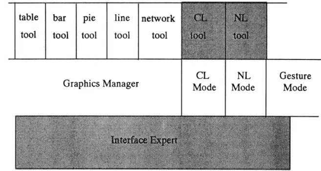
suggestion. Therefore five graphics tools have been developed !o display tables, histograms, line
and scatter graphs, and building and network geography.
In
orderto
generalisethe
intelligent interfaceto
other domains, newCAD
tools should bedesign constraints:
1.
Individual tools must be accessible for different functions2.
A Graphics Manager which provides a clear inlerface between all tools and the rest of the MMI2 interface must be provided. l.,lew tools can be added to this manager.3.
A window manager is used to facilitate portability. The cunent window manager used isSun-Viewÿhough
their are plans to port the system to the rnore general X-windows managerIn operation, the graphics manager receives CMR packets from the rest of the interface, which are
decomposed so a tool can be selected to display the information. The CMR is then translated into
the internal representation required for thât tool which opens a window and presents the information graphically. The selection of the appropriate tool is made by a rule set which assesses the structure
of the information and accesses the User Modeling Expert to determine the preferences of the user.
The rules determine the structure of gnphs and chars draw on the methods proposed by Tukey (1977), Cleveland (1985), Beach (1985) and Mackinlay (1986). When a user makes a selection or modification this is translated into CMR by the graphics manager which passes the packet dorm to
the Dialogue Controller. Figure 5 shows an interaction
with
the system illustrating the range ofgraphics tools.
The graphics tool to allow the presentalion and manipulation of building and network geography is
the most complex. This allows users to enter building geography as a free hand sketch which is then
digitally sampled and adjusted to turn wavy free hand lines into straight lines and the square up
angles between these lines. Linked planar maps are used to represent the building and network
geography so that either may be viewed and modified separately, as well as together. This approach
of allowing free hand input with a smoothing process was chosen rather than the conventional use
of a menu selected 'straight line' tool with handles to move it, since it fits the details of the style of
the observed experts better.
8.2.INTERFACE EXPERT
The Interface Expert serves three main roles in the MMI2 system:
Declarative Knowledge of the MMI2 Interface is stored in a knowledge base in the Interface Expert.
This is called upon by the dialogue controller when the user asks questions about the limitations, abilities, structure or components of the interface itself rather than the domain. For example, if the
users asks "What natural languages can
I
user here?" the knowledge that English, French andSpanish are available would be provided by this knowledge base.
Screen layout managemenl is performed by the interface expert in as far as it provides windowing tools with a position in which to appear on the screen. This ovenides the default algorithm in the
window manager to position windows in task relevant positions rather than progressively across the screen. The need for this role arises since the windows within the application are overlapping rather than tiled to allow more flexibility in dialogue.
Text interaction in natural language and command language is performed in a pair of windows which are part of the interface expert. Once text is input and a carriage return typed, the string is sent
to the appropriate natural or command language mode which returns a CMR packet that is setrt to the Dialogue Controller. This provides a uniform image to the user which rnay not occur if separate
Insert Figure 5 here
Figure 5: Example of an interaction with MMI2. The windows in the upper left and center show a toc
in which the user can enter details of buildings and computer networks
for
those buildings, andi
which MMI2 can display design solutions. The windows on the right and bottom show tools for th system to display answers as charts
or
tables. The windowin
the middleleft
supporls comlnan, language and natural language interaction. Users can perform design gestures in any of these windowlinteraction windows were developed for each text mode. These windows are pârt
of
the interface expert rather just another graphics tool since they include the main event handling procedures for the interface, and support the gesture modein
different windows. Consequently the gaphicsmanager actually passes its CMR packets through the Inlerface Expert to the Dialogue Controller. This provides a clear interface between all modes and the dialogue controller as shown in figure 6.
USER
window
manager (Sun
View
/
X-windows)
Graphics Manager
Gesture
Mode
Figure 6: Layered interaction of the graphics and text tools
with
thewindow
manager. Shaded âreas are partof
the Interface expert.8.3. COMMAND T-ANGUAGE
The purpose of the command language (CL) is to provide users with a language based mode but
without the computational overhead associated with a
full
natural language. The improvement inspeed is offset by a cost to the user in terms of syntactic structure : users are required to comply with the syntactic constraints of the CL. The CL comprises a syntacfic part and a semantic part. The
syntactic part comprises two data sets: a set
of
operators/actionsor
commands such as 'add', 'connect' etc. and a set of application objects which are common or proper nouns.A
command comprises an action-object pairing. In order to determine whether the command conforms $/ith thetable
tool
bar
tool
ple
tool
line
tool
nettwork
tool
CL
Mode
NL
Mode
semantics of the application the cornmand is coded in CMR and passed for evaluation. The Semantic Expert determines whether the pairing is legitimate and returns and evaluation.
8.4. GESTURE MODE
As the complexity of graphical representations of a network increases the efficiency the efficiency of natural language modes of dialogue tends to decrease while the use of direct manipulation tends to increase. Designers routinely use a wide range of non-standard but familiar graphical annotations
to their work plans in order to edit and modify them. Moreover, they usually retain a cumulative
record of this part of the design process using it as an aid to quality conlrol in a design audit trace.
Thus, the use of 'design shorthand' is an integral part of the design process and the MMI2 interface permits designers to continue to use this mode of dialogue.
An algorithm has been implemented which allows designer to draw up to L9 different shapes. The
shapes are recognized as commands (e.g. 'delete', 'transpose') within the application. Users can
draw onto a graphical representation
of
a plan and make technical modifications. For example,designers can remove graphical objects by 'scribbling' over them or transpose objects by drawing
the appropriate shape around the objects to be transposed. The algorithm recognizes the shape
drawn by the user (the syntactic part of the process) and pairs it with the objects around which it has been drawn (the semantic part) for subsequent evaluation by the Semantic Expert. The algorithm is
scale, location and style invariant. In other words the shapes can be drawn to different scales, in any location using a wide range of individual drawing styles. Improvements in the algorithm
will
satisfyrotational invariance, allowing users to draw the shapes in a varieÿ of orientations. The algorithm can be used
in
a
varietyof
applications where designers routinely employ graphical, gesturalshorthand within the design process. 8.5. SPANISH LANGUAGE MODE
The Spanish System is envisaged around two components: an analysis module and a generator. The latler is to be implemented from L9ÿ2 on.
The analysis module includes a morpholexical component that does an extensive morphological
analysis of Spanish - including resolution of collocations and idioms likecable delgado (thin cable), de todns formas (anyway), tener en cuenta (to take into account), etc.
The result of the moqphological process is a graph that reveals the set of categorical ambiguities in
a given input texl.
It
is worth saying that some of these ambiguitieswill
be solved with the aidof
statistical methods. læxical lookup is performed upon that pruned graph. This component is entirely written in C. The approach adopted is extremely lexicalist. The assumption is that lexical enlries are
rather huge structures containing
a lot
of
information (selectional restrictionsfor
arguments,semantic typing for CMR formulas, etc.)
The output information
from
the morphological componentis
the inputto a
syntactic parser(developed in BIM_Prolog) that yields a CMR representation by means of a compositional
feature-based formalism grounded on functional dependency grammâr (cf. Kaplan and Bresnan [1982], Kay [1985]).
A
formalism has been devisedthat
extensively supports several typesof
featuremanipulation: unification, constraint evaluation, and value overlapping. This parser is currently
Some parts of the parser
will
inæract with other modules of the MMI2 systetr! in order to solve problems like word sense and attachment ambiguiües ellipsis or anaphora, that need contextual andworld knowledge.
8.6. FRENCH I.-ANGUAGE MODE
The French processing system
will
include both the analysis ofNL
utterances in order to reach aCMR expression and the generation of the expert system ânswers. The objective of NL analysis is not to build any possible parse, but only the right ones. Concurrently, the generation system has to
buiid a NL answer according to the user expectations.
The approach to French NL analysis has the following characteristics:
.
the ana\yzer is modular; it is made of little modules associated with limited tasks.'
the analysis is driven by the content of the l.{L sequences: at each step, all the accurateinforma-tions are stored, and are used for local prediction, in order to avoid to build spurious solutions. The steps of the analysis are:
.
preprocessing,which
normalizes the inputNL
sequence,'
morphological analysis, associatedwith
a
50 000 wordsdictionary which
tags eachword
with
its lexical entries, grammatical categories, etc.'
disambiguationof
the sequence of categories based on a Markovianfilter,
.
segmentationof
a sentence in clauses,'
parsing of each clause through a Earley's automaton which is supervised by a linguisticexpert system,
'
transformationof
the constituent structure^s in a categorical formalism. Inside this for-malism, some operations like anaphora resolution, modification of the word order...,üo
done in order to reach a CMR expression.The first state of the analysis, producing the constituenl structures, has been implemented in C; the rest of the parser is currently under development.
8.7. ENGLISH LANGUAGE MODE
The English NL input mode of MMI2
will
use the English parser of the LOQUI system, developedfirst within the context of the LOKI ESPRIT project (P 101 [Binot et al. 88], then within an internal development project called BIM_LOQUI.
LOQUI consists
of
a numberof
heavily intenelated modules, among which the following main components can be distinguished: morphology, pars€r and interpretrtion module on the analysis side and response determination module and generator on the generation side. These processing modules make use of several sources of knowledge: the lexicon, a body of morphological rules, a body of "dat;abase mapping rules", a "world model" including general semantic knowledge aboutword meanings as well as pragmatic knowledge of the application domain and a dialogue memory
holding the discourse structure represontation.
Grammar (GPSG) [Gazdar et al. 85] but allows mechanisms from other theories as they seem useful, the aim being to develop an implementation of English gramnnar which is not only theoretically
sound but also computationally efficient. Prolog itself is the formal expression language
of
theEnglish grammar, mainly for reasons of efficiency.
The work required to adapt the LOQUI parser to MMI2 is rather limited, due to the portable natüe of the system. This work, which is currently under way, mainly includes:
.
defining an appropriate lexicon for the domain of the application (computer network design);.
defining an appropriate conceptual model for the domain of the application; this is related to thedesign of the "Semantic Expert" introduced in the general architecture;
.
modifying the output of the parser so that it generates CMR expressions;.
improving some aspects of the parsing itselt mainly from the point of view of extending itscov-erage and/or efficiency.
9. Conclusions
We
have presentedwhat
should probablybe
considered as an ambitious architecturefor
amultimode interface system, including concerns such as user modeling, communication planning,
multimodal meaning representation, dialogue context management, etc. Vle do not necessary expect
to develop all above mentioned features to the same degree of completeness within the scope of this
project. But we see the architecture itself, which we tried to describe in a clean and modular way,
as a kind of reference framework for further research and implementation work on these topics.
The
MMI2
project itselfwill
eventually produce an interface prototype illustrating (maybe atvarious stages of completion) all aspects of the proposed architecture. In this respect, the current
phase of the project is focused on the implementation of prototypes for the various components
of
the system, including the various input - output modes and on the integration
of
someof
theseprototypes in a first version of the multimodal system.
10. References
Allen
J. (1983) Recognizing Intentionsfrom
Natural l,anguage Utterances.In
M.Brady
&
R.C
Berwick (Eds)
"Computational
Models
of
Discourse". CâmbridgeMA: MIT
Press.Beach, R.J. (1985), Setting tables and illustrations
with
style.
PhD.thesis, Departmentof
Computer Science, University of Waterloo, CanadaBinot J-L.,
Demoen8.,
HanneK.H.,
SolomonL.,
Vassiliou
Y., von
Hahn V/.,Wachtel
T.,
(1988),
LOKI:
A
logic
Oriented Approach
ro
data
andknowledge bases supporting Natural I-anguage Inüeraction, Proceedings
of
the ESPRITS8 Conference, North-Holland.of
the "'VÿorkWith
Display
Units"
Second Conference,Montréal,11'14
Sept. 1989. Amsterdam: ElsevierCanberry,
M.S.
(1985) "PragmaticModelling
in
Information
System Interfaces." Ph.D. thesis, Universityof
Delaware.Cleveland (1985), The elements
of
Graphing Data, Wadsworth Advanced Books and Softrvare: Monterey, California.Finin
T.
and Drager
D.
(1986)."GUMS:
A
GeneralUser
Modelling
System." Technical Report MS-CIS-S5-35, Department of Computer and Information Science, U.of
PennsylvaniaGazdar G.,
Klein E.,
PullumG.
and SagI.,
(1985), Generalized Phrase Structure Grammar, Blackwell.Genesereth,
M.R.,
Nilsson,
N.J.
(1987),
Logical
Foundations
of
Artificial
Intelligence (Morgan Kaufmann Pub., I-os Altos,CA).
Grice, H.P. (1975) I-ogic
and C.onversation.In P.
C-ole andJ.L.
Morgan
(e.ds.)"Syntax
and Semantics",volume
3,
pages 64-75, Academic Press, NewYork
Julien
C.
and
Marti
J-C. (1989),: Plan revision
in
person-machine dialogue, Proceedings of the FourthACL
European Chapter Conference, Manchester. Kaplan R. and Bresnan J. (1982), læxical-functional grammar:A
formal systemfor
grammatical representation, in J. Bresnan (ed.) The Mental representation
of
Grammatical Relations. TheMIT
Press.Kaplan
S.J.(1983)
Cooperative Responsesfrom a
PortableNatural
languageDatabase
QueV
System.
In
Brady,
M.
and
Berwick,
R.C.
(eds) "Computational Modelsof
Discourse". CambridgeMA: MIT
Press.Kass, R.J. (1988)
"Implicit
Acquisition
of
User Modelsin
Cooperative Advisory Systems" Technical Reports MS-CIS-878-05, Department of Computer andInformation Science, U.
of
PennsylvaniaKass, R.J. (1988)
"Acquiring
aModel
of
the User's Beliefsfrom
a
Co-operativeadvisory Dialogue."Technical Reports MS-CIS-88-L04,
Departmentof
Computer and Information Scien@, U. of PennsylvaniaKay
M.
(1985), Parsing
in
functional
unification grammar,
in
D. Dowÿ,
L.U.Press, PP.25l'278.
Mackinley,
J.
(1986), Automating the
Design
of
Graphical
Presentationsof
Ràhtional
Information,ACM
Transaction on Graphics, 5(2),110-141 pollack,M.E.
(1936)"Inferring
Domain Plansin
Qr.lestion-Answering". TechnicalReport MS-SIC-86-40, Department
of
Computer andInformation
Science,Univ. of
PennsYlvania.Sparck Jones