*[email protected]
1
Assessment of HVDC Frequency Control Methods in the Nordic Test System
D. OBRADOVIC
1*, M. DIJOKAS
2, A. TOSATTO
2, T. VAN CUTSEM
3, R. ERIKSSON
4,
M. GHANDHARI
11
KTH Royal Institute of Technology,
2Technical University of Denmark (DTU),
3University of Liège,
4Svenska kraftnät
Sweden, Denmark, Belgium
SUMMARY
The Frequency Containment Reserve (FCR) is one of the balancing actions to keep the frequency within acceptable limits. The objective of the FCR (also known as primary frequency control) is to stabilize the system frequency within a short time interval after a disturbance. Related to that, maximum steady-state frequency deviation and maximum Instantaneous Frequency Deviation (IFD) are defined. With higher integration of renewable energy sources, power systems will reduce its impact on pollution, but face much more often with low inertia scenarios. With low inertia values, the system decreases its inherent property to react to large power disturbances. In these cases, IFD is profoundly affected, and there is a need for fast and cost-effective solutions.
High-Voltage Direct-Current (HVDC) links, with appropriate control strategies, could offer a solution to this problem. According to current system requirements, HVDC links must be capable of providing frequency support. Several studies have focused on control methods that adjust the power output of HVDC converters in response to frequency deviations; however, which method performs best in terms of reliability, robustness, and cost-effectiveness has still not been proved.
The aim of this work is to apply and compare two control methods for HVDC frequency support in a test system representing the Nordic Power System (NPS), where this control mode is referred to as Emergency Power Control (EPC). The first method, the current paradigm in the NPS, is based on ramp power injections and frequency triggering activations. The second method, here proposed as the method for future EPC operation in the NPS, is a droop frequency-based EPC. The performance of these two methods is tested for two different disturbances, with the same EPC power capacities. The main objective of the EPC is to meet the frequency requirements and avoid any negative interactions. The results show how the new proposed method outperforms compared to the current one, highlighting the benefits of a change of paradigm. The Nordic test system has been designed by authors to capture the frequency response of the NPS. Additionally, a single machine model is used to study the performance of the proposed EPC for the low inertia scenarios.
KEYWORDS
Droop Frequency Control, Emergency Power Control, Frequency Containment Reserves, HVDC Frequency Support, Low Inertia System, Nordic Power System.
2
I. INTRODUCTION
With ambitions of reducing carbon emissions, future power systems will progressively integrate larger shares of Renewable Energy Sources (RES) to phase out conventional thermal and nuclear generators. Since RES (such as wind and solar power units) are connected to the grid by means of power electronics devices, they do not inherently contribute to system inertia. Inertia represents the ability of power systems to oppose changes in frequency after a disturbance; with decreasing inertia, the Instantaneous Frequency Deviation (IFD), which follows a power unbalance, is significantly impacted. For stabilizing the frequency, different frequency response products have been designed and integrated into existing ancillary services markets. Frequency Containment Reserves (FCR), also known as primary frequency control, provide a fast dynamic response to stabilize the frequency within a short time interval after a contingency. The requirements for these reserve products are based on the maximum allowed IFD and Steady-State Frequency Deviation (SSFD) [1].
Large power disturbances result in large IFDs, which may activate frequency protection schemes, such as under-frequency load shedding and generator tripping. In order to meet power quality requirements, Transmission System Operators (TSOs) try to avoid such measures. During large disturbances, FCRs should provide an appropriate dynamic response to restore the power balance before the frequency leaves the allowed range. In power systems with low inertia, the time frame for power balance restoration drops to a few seconds. Consequently, the governor's controllers should be tuned appropriately, taking into account the physical properties of the turbine and the water (steam) flow [2].However, system operators cannot always guarantee that all FCR units are capable of providing such a service within stated requirements.
Due to their fast dynamics and flexible operation, additional support can be provided from High Voltage Direct Current (HVDC) interconnections in the form of Emergency Power Control (EPC), when they are available for such support [3]. ENTSO-E report [3] states that an HVDC link should be capable of providing fast active power as frequency support. Still, it does not oblige HVDC link to serve any (arbitrary) frequency support, since AC system dynamics is affected as well. Previous research focused on testing usage of HVDC link frequency support through different system models and HVDC controller designs. The various studies focused on the influence of capacity limits, power rate limits, and HVDC frequency support methods comparison [4]-[14].
Dynamics of the generators involved in FCR play an essential role in designing EPC support. The work [4] assessed the governor (and generators in general) dynamics and its influence on minimum requirements towards EPC dynamic response. Minimum EPC requirements are crucial for system operation, and they indicate a range of values for which EPC methods should be evaluated. Otherwise, a random gain/ramp constant gives only vague information about EPC performance.
This work investigates a comparison between two EPC methods for the two disturbance scenarios. The first EPC method is the one currently implemented in the Nordic Power System (NPS). It is based on the ramp power injections (in several steps) after frequency triggering activations, with data provided in [15]. The newly proposed EPC method is based on a droop frequency control and a lower and unique frequency-triggering value. For both methods, the same EPC power capacities are used. The main objective of these two methods presented is to keep the IFD within the required frequency limit and to observe the EPC and FCR power required for such actions.
For case studies, the Nordic test system is designed to assess the two EPC methods and the system frequency response. Two cases of disturbances are applied to this test system, and for both of them, the lowest (close to) estimated amount of inertia is used. The first case is the worst-case scenario in which the largest generation unit is tripped – the largest active power disturbance according to the N-1 criteria. In the second one, a less severe disturbance is applied since this kind of disturbances are more prone to happen, and proper EPC response should be guaranteed. Furthermore, an equivalent single machine model (proposed by ENTSO-E) with low inertia is used to study the performance of the frequency droop based EPC.
3
II. MODELING AND STRUCTURE OF THE NORDIC TEST SYSTEM
For frequency control analysis simplified generator model (2-order dynamics with governor/turbine system) is usually found to be sufficient. In that way, the only active power balance in the system is assessed, and voltage dynamics are neglected. By doing so, the challenges of designing higher-order dynamics and components are avoided. However, with the introduction of the new HVDC frequency control methods, the overall stability should be guaranteed, and negative interactions ought to be avoided. That is why, for the purpose of assessment of the new HVDC frequency support method, a test system that includes various dynamic phenomena is designed and tuned in PowerFactory software.
The analysis is established for the case of NPS equivalent, where this system also includes HVDC interconnections (some of them are involved in EPC) - illustrated in Fig. 1, and generator equivalents of Continental Europe and Baltic countries.
The Nordic test system is represented as a transmission grid where the distribution grid quantities (i.e., generation, load, wind generation) are modeled as aggregated representations at the transmission voltage level. The model comprises of 474 transmission busses and 81 synchronous machines (providing approximately 26.5 GW), of which ten are involved in FCR. By introducing 14.4 GW of wind generation (modeled as negative loads) in the Nordic test system, the kinetic energy level of the system is adjusted to 131.2 GWs (before disturbance) – close to lowest estimated one in the NPS which is 120 GWs [2]. The connection to the other asynchronous areas is
Figure 1. Nordic system map (purple color) with HVDC interconnections to other synchronous areas (apart from Fennoskan).
GERMANY POLAND LITHUANIA ESTONIA RUSSIA THE NETHERLANDS NORDBALT KONTEK RG Continental Europe RG Nordic RG Baltic REGIONAL GROUPS LATVIA
FINLAND
SWEDEN
NORWAY
BELARIUS UKRAINE (RU)4
achieved by introducing 17 HVDC connections, twelve of which are modeled as Line-Commutated Converters (LCC), and five as Voltage Source Converters (VSC). The initial steady-state frequency was set to 49.9 Hz - the lowest value where Frequency Containment Reserves for Disturbances (FCR-D) are not activated.
Generators are modeled as 5/6th order models (salient pole/round rotor type) with excitation system type SEXS. Additionally, all generators in the Nordics except DK2 contain power system stabilizer type STAB3 that was tuned to provide a sufficient amount of system damping. All parameters were taken as typical ones for the given nominal power and voltage level, and generator type. Ten hydro units involved in FCR-D contain HYGOV/TGOV1 governor/turbine system.
LCC HVDC links were modeled as a two-port element connected to 2-winding transformers and capacitor banks at Point-of-Common Coupling (PCC). The two-port element includes rectifier and inverter (equipped with dynamic control), and DC cable. In addition, the converter station is equipped with two slow controllers for transformer tap changer and switching shunt.
HVDC VSC stations are represented as an average model, two-level voltage sources with the DC capacitor and in series connected RL phase reactor. The inner PI converter controllers were carefully tuned to provide a satisfying response.
All converters located in NPS are providing the reference for active and reactive power, while others are responsible for the control of DC voltage. Furthermore, the chosen HVDC links, the same one as in [15], have an EPC service implemented, but their availability (EPC capacity) of providing it could be limited due to power flow scenario.
III. METHODOLOGY OF AN HVDC EPC
To ensure frequency stability, system operators require an appropriate dynamic response from the generator units involved in the FCR. The proper dynamic response is related to the ability of FCR units to increase (change) the mechanical power output within a specified time (for the given frequency input). The requirements are set concerning open/closed-loop analysis. One way to make units react faster is to establish stricter requirements and simply require more power (or the same power within less time). However, synchronizing machines have physical limitations, and, for even lower inertia values, they might not be capable of providing the necessary power. Additionally, creating too aggressive (high gain) governors could lead to a decrease in the closed-loop stability margin. On the other side, it is questionable if, in practice, governor settings are appropriate and able to meet presented requirements.
HVDC systems provide a high level of flexibility and fast active power control. Even though there are plenty of ways to use HVDC links, system operators are generally looking into reliable, cost beneficial and simple solutions. Implementing static EPC, based on local measurements, is a convenient way to support FCR. Usually, it is applied if there are already available HVDC interconnections for such support.
III.i. Principles of the currently implemented ramp/step EPC HVDC method in the NPS
The control method for currently implemented EPC in the NPS is presented in [15]. This method is referred to as the "ramp/step" method, and it provides a static response. This power is distributed in several steps (different for each HVDC link) containing the following properties:
• frequency activation level (Hz),
• step capacity (or total EPC capacity) (MW), • step ramp (MW/s), and
• time hold (s),
where these values are set by the respective TSO(s) and presented in [15]. The working principle is illustrated in Fig. 2 with a blue color. Provided figures are obtained from the test case of an equivalent single machine model [2] (used for FCR analysis).
5
After a disturbance, the change in frequency triggers the EPC. HVDC power is injected with defined ramps in terms of (MW/s), where each of the steps contains the capacity limit (MW) together with the total EPC limit. The implemented ramp/step method and its control settings are recognized as sufficient for the higher inertia scenarios. However, poor performance in the low inertia cases is identified in this work.
III.ii. Principles of proposed EPC HVDC droop frequency method for the NPS
The idea of introducing a new EPC method is to shift the HVDC frequency control from open-loop to closed-open-loop control type. The solution, which is considered simple and robust, is droop frequency control. In this way, after the EPC activation, the injected power is proportional to the local frequency deviation (from activation value), and there is no need to create separate frequency activation levels, while EPC gains (MW/Hz) can be distributed among HVDC links. The example of an EPC droop frequency response is presented in Fig. 2 with orange lines.
IV. RESULTS FROM THE NORDIC TEST SYSTEM
IV.i. Case A: The largest power disturbance according to N-1 criteria
In the previously introduced multi-machine Nordic test system model, the system response and performance of the presented HVDC EPC methods ware assessed. The reference incident (Oskarshamn 3 - 1450 MW) was applied, and it is referred to as case A. With respect to different frequency support services, four main cases were analyzed:
• No EPC support
• Ramp/step EPC method with limited capacity • Droop frequency EPC method
• Ramp/step EPC method with sufficient capacity on available HVDC links
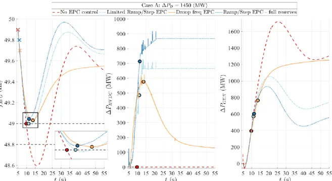
The main results of these case studies are presented in Fig. 3: average frequency (left), total system EPC power (center), and total mechanical power contribution from FCR-D units inside the Nordic system (right).
Initially, the system response without EPC control is tested, in Fig.3 red dashed line. In this case, only units providing FCR are responsible for keeping the frequency within limits. They were designed to provide 3625 (MW/Hz) of regulating strength (minimum SSFD=0.4 Hz and 1450 MW of disturbance). However, the governor's response is not sufficient to meet the frequency requirement (49.0 Hz) and avoid load shedding at 48.8 Hz.
6
The EPC that is currently implemented in the NPS (method and control settings) were used in the second case study - light blue dash-dotted lines. HVDC links have 673 MW of available EPC capacity. As a result, substantial improvement in frequency response compared to the "No EPC" case was achieved. Nevertheless, the frequency minimum (nadir) is still lower than 49.0 Hz.
In the third case study, the EPC droop frequency method was tested – full orange lines in Fig.3. The total HVDC gain is chosen to satisfy the frequency requirement (f>49.0Hz) and distributed to avoid violating EPC capacity limits (no HVDC EPC limits are reached). HVDC links with EPC function are activated from 49.7 Hz. This value is arbitrary chosen in order to be low enough to avoid activation during "small" disturbances, but still to be fast enough to support the system in the bigger ones and not require too high EPC gains. In comparison to step/ramp EPC case, droop frequency EPC provided smaller frequency deviation and smaller oscillations during the frequency settling. Maximum EPC power is lower, while EPC energy is substantially lower, which also affects the impact in the other end – Continental Europe (CE) power system.
As a further analysis, the aim was to satisfy the frequency requirement by using the ramp/step EPC method, but not to change the control settings. In order to do so, the EPC capacity of Baltic
Figure 3. System response for different cases of frequency support through FCR and HVDC EPC for the largest dimension incident in the Nordic test system – case A
7
Cable is set to be fully available (from 100 to 300 MW - total EPC equal to 873 MW) – the case with a darker blue dotted line in Fig.3. The cost of providing a better frequency minimum is a substantial increase in injected EPC power and energy. Additionally, the frequency swing is even more present and could lead to undesired over-frequency activation.
In all tested cases, the total FCR mechanical power response is highlighted with the exact values in moments when frequency ether crosses 49.0 Hz or reaches the minimum. It is interesting to observe that with a better EPC design, there is a more efficient response of mechanical power as well.
From Fig. 3, it is noted that less, or in some cases much less, EPC power/energy is required, which is also reflected in a positive way to the response in the CE power system. The obtained CE frequency behavior is presented in Fig. 4, and a better contribution of droop frequency EPC is obvious – uses less power/energy.
IV.ii. Case B: "Smaller" power disturbance
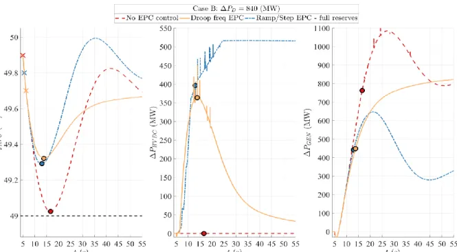
In the previous analysis, different EPC method was designed to support the frequency response for the currently estimated worst-case scenario, which was the initial goal. Anyhow, it should be noted that this scenario is improbable to happen. That is why it is essential to analyze the system behavior within other more probable, but less severe disturbances, and compare the performance of implemented EPC methods. In this case, referred to as case B, the system response was tested for a disturbance of 840 MW generation loss in SE2. Droop frequency and step/ramp with a sufficient amount of reserves are presented. As it is demonstrated in Fig. 5, generation units were capable of keeping the frequency within limits, so no EPC support services were necessary.
Nevertheless, EPC is a feedback control method, and (so far) there is no infrastructure to identify the amount of disturbance immediately after the event, so this method cannot be applied as feed-forward control. It implies that EPC must be activated even though it is not necessary. In addition, with current EPC, there is always a trade-off between dead-band and power ramp rate. The comparison provided in Fig. 5, droop frequency EPC produces better frequency response in terms of IFD (slightly) and, which is even more critical in this case, does not create potential over-frequency swings, implying a higher stability margin. A ramp/step method injects (sometimes
Figure 5. System response for different cases of frequency support through FCR and HVDC EPC for generator loss of 840 MW in SE2 – case B
8
unnecessarily) a large amount of power with a steady-state contribution, and after the frequency nadir, oscillations in frequency response are to be expected.
IV.iii. EPC methods and power flow analysis
As can be noted from Figs. 3 and 5, there is a significant difference in steady-state power contribution between EPC methods presented. In the currently used EPC method, the maximum injected power is the same as the one provided in steady-state. On the other side, the steady-state contribution of the EPC droop frequency method is proportional to the frequency deviation (from triggering activation level), and it is much less than the maximum injected EPC power in this case. It implies that, by using the ramp/step EPC method, there is more power provided by HVDC and less by generators, compared to the case where the HVDC droop frequency method is used.
Depending on the cases observed, different EPC methods provide a better post-disturbance load flow state. In some cases, injecting more power from HVDC links could reduce the system stress. For example, a disturbance in the South of the Nordic system could benefit more from a larger power EPC contribution. In that way, it avoids stressing the tie-lines corridors that connect hydro generation from North to consumption in the South. On the contrary, with a power disturbance in the North of Nordic system, less EPC power contribution is desired and more from Northern generators.
Nevertheless, using HVDC droop frequency control, the steady-state frequency deviation is easily determined by knowing the amount of disturbance and total regulating strength of the system (the same as the "only generator" case). In the case of ramp/step EPC, the steady-state frequency deviation is a function of inertia (since different steps are activated depending on how low the frequency drops, which depends on inertia), which implies higher uncertainty in load flow distribution and power dispatch.
The conclusion is that careful design of droop frequency EPC, with no additional infrastructure, can provide:
1. Better frequency response (lower frequency deviation) • No activation of frequency relays
• Frequency quality 2. Less HVDC power used:
• Lower cost of provided EPC service
• Stressing of the sending-end system (less frequency deviation in CE) • Controlling the post-disturbance power dispatch
3. The lower level of frequency triggering value
• Avoid unnecessary activation of EPC support during “smaller” disturbances • Lower cost of the EPC service on a long time scale
V. FUTURE INERTIA SCENARIOS WITH DROOP FREQUENCY EPC
By using a comprehensive multi-machine system, we aimed to test the new EPC method (droop frequency) and provide a comparison to the one currently used. For further analysis, the equivalent single machine system is used (voltage dynamic is neglected). The case studies focused on required EPC actions and frequency response with different values of inertia. In Fig. 6, the cases have a total kinetic energy of 100, 80, and 60 GWs. The results are presenting the required EPC actions to keep the frequency above 49.0 Hz, given the reference incident. Assuming that system operators aim to improve the governor response, the same cases of inertia and EPC droop frequency method are presented with improved governor settings without changing the amount of regulating strength – red lines in Fig. 6.
Obviously, with decreasing inertia, the needed amount of EPC power increased. Relatively high values of inertia (100 GWs in this case) with the improved governor settings significantly reduced
9
the amount of required EPC power, while steady-state generators reserves remained the same – implying less total costs. On the other side, moving towards a meager amount of inertia values (60 GWs), there are no significant changes in terms of maximum power provided. In these cases, the frequency control depends mainly on the careful design of HVDC frequency support. Meaning that the future frequency control essentially belongs to fast controllers, and it is vital to increase the confidence in applied control methods by thorough analysis and, as well, practical testing.
VI. CONCLUSIONS
The ongoing displacement of conventional synchronous generation is gradually resulting in lower power system inertia. Thanks to their fast dynamics and flexible operation, HVDC lines can be used for the provision of frequency support using the Emergency Power Control functionality. In this paper, the performance of two control methods for EPC has been tested on a multi-machine model representing the Nordic Power System. The first method, the current paradigm, relies on fixed power injections while the second, presented in this paper, on droop frequency control.
The results presented in the paper show that both EPC methods are able to substantially improve the IFD in case the reference incident (the loss of Oskarshamn 3) occurs. However, droop frequency EPC reduces the IFD using much less power (and energy), and does not cause frequency swing after reaching the nadir. Moreover, the droop frequency method uses a single and lower frequency triggering value and avoids unnecessary activation for small power disturbances. Finally, with droop frequency EPC, there is higher controllability over post-disturbance power dispatch, which can be important for preventing line overloading and cascading faults.
Furthermore, by using a single machine equivalent system, the performance of droop frequency EPC is presented for "extreme" low values of inertia, where frequency requirement is satisfied as well. The work highlighted the importance of proper tuning of governor's settings. The results illustrate that they can play a crucial role in frequency response and reduce the requirements towards EPC. However, for the lowest tested inertia case, most of the transient contribution goes to EPC, and that is why their careful design is of high importance.
Figure 6. Low inertia scenarios with EPC droop frequency method in a single machine equivalent system.
10
VII. ACKNOWLEDGMENT
This work is supported by the multiDC project, funded by Innovation Fund Denmark, Grant Agreement No. 6154- 00020B, and as well by Swedish Transmission System Operator - Svenska kraftnät.
BIBLIOGRAPHY
[1]
P. Kundur, Power System Stability and Control, New York: McGraw Hill, 1994.
[2] M. Kuivaniemi, N. Modig, R. Eriksson, “FCR-D Design of Requirements”, ENTSO-E Report, July 2017.
[3] European Commission, “COMMISSION REGULATION (EU) 2016/1447 establishing a network code on requirements for grid connection of high voltage direct current systems and direct current-connected power park modules,” Official Journal of the European Union, Art 15, August 2016.
[4] D. Obradovic, M. Ghandhari, R. Eriksson, “Assessment and Design of Frequency Containment Reserves with HVDC Interconnections”, 2018 North American Power Symposium (NAPS), pp. 1-6, Sep. 2018.
[5] L. Papangelis, X. Guillaud, T. V. Cutsem, “Frequency support among asynchronous AC systems through VSCs emulating power plants”, 11th IET International Conference on AC and DC Power Transmission, pp. 1-9, Feb. 2015.
[6] S. P. Teeuwsen, R. Rössel, “Dynamic Performance of the 1000 MW BritNed HVDC Interconnector Project”, IEEE PES General Meeting, pp. 1-8, July 2010.
[7] J. Huang, R. Preece, “HVDC-based Fast Frequency Support for Low Inertia Power Systems”, 13th IET International Conference on AC and DC Power Transmission, pp. 1-6, February 2017. [8] J. E. S. de Haan et al., “Stabilising system frequency using HVDC between the Continental
European, Nordic, and Great Britain systems”, Sustainable Energy, Grids and Networks, vol.5, pp. 125-134, 2016.
[9] C. E. Spallarossa, Y. Pipelzadeh, T. C. Green, “Influence of Frequency-Droop Supplementary Control on Disturbance Propagation through VSC HVDC Links”, IEEE Power Energy Society General Meeting, pp. 1-5, July 2013.
[10] A. G. Endegnanew, K. Uhlen, “Global Analysis of Frequency Stability and Inertia in AC Systems Interconnected through an HVDC”, 2016 IEEE International Energy Conference, pp. 1-6, April 2016.
[11] L. Papangelis et al., “Decentralized Model Predictive Control of Voltage Source Converters for AC Frequency containment”, International Journal of Electrical Power and Energy Systems, vol. 98, pp. 342-349, 2018.
[12] E. Mallada, “iDroop: A Dynamic Droop controller to decouple power grid's steady-state and dynamic performance”, 2016 IEEE 55th Conference on Decision and Control (CDC), pp. 4957-4964, Dec. 2016.
[13] D. Martin, W. Wong, G. Liss, B. Arnlov, T. Jonsson, J. Gleadow, and J. de Silva, “Modulation controls for the New Zealand DC hybrid project”, IEEE Transactions on Power Delivery, vol. 6, no. 4, pp. 1825-1830, Oct. 1995.
[14] J. Fradley, R. Preece, and M. Barnes, “VSC-HVDC for frequency support (a review)”, 13th IET International Conference on AC and DC Power Transmission (ACDC 2017), pp. 1-6, Feb. 2017. [15] E. Ørum et al., “Future System Inertia 2”, ENTSO-E Report, August 2016, pp. 31-41, 94-98.