HAL Id: hal-01276607
https://hal.archives-ouvertes.fr/hal-01276607
Submitted on 19 Feb 2016
HAL is a multi-disciplinary open access
archive for the deposit and dissemination of
sci-entific research documents, whether they are
pub-lished or not. The documents may come from
teaching and research institutions in France or
abroad, or from public or private research centers.
L’archive ouverte pluridisciplinaire HAL, est
destinée au dépôt et à la diffusion de documents
scientifiques de niveau recherche, publiés ou non,
émanant des établissements d’enseignement et de
recherche français ou étrangers, des laboratoires
publics ou privés.
Safety Analysis of a Medical Robot for Tele-echography
Jérémie Guiochet, Adriana Vilchis
To cite this version:
Jérémie Guiochet, Adriana Vilchis. Safety Analysis of a Medical Robot for Tele-echography. 2nd IARP
IEEE/RAS joint workshop on Technical Challenge for Dependable Robots in Human Environments,
Toulouse, France, Oct 2002, Toulouse, France. �hal-01276607�
Safety Analysis of a Medical Robot for Tele-echography
J. G
UIOCHET
LESIA
Electrical and CS Eng. Dpt., INSA, 135 Av. de Rangueil 31077 Toulouse cedex4 France
email : Jeremie.Guiochet@insa-tlse.fr
A. V
ILCHIS
TIMC/IMAG GMCAO Faculté de Médecine de Grenoble
38706 La Tronche France email : Adriana.Vilchis@imag.fr
1. Motivations
Among many types of medical equipment, ultrasound di-agnostic systems are widely used because of their conve-nience and safety. Performing an ultrasound examination involves good eye-hand coordination and the ability to in-tegrate the acquired information over time and space. Some of these specialized skills may lack in some healthcare cen-ters or for emergency situations. Tele-consultation is there-fore an interesting alternative to conventional care. Devel-opment of a high performance remote diagnostic system, which enables an expert operator at the hospital to examine a patient at home, in an emergency vehicle or in a remote clinic, may have a very significant added value. There-fore a robotic tele-ultrasound system is proposed in order to realize the examination in small towns or cities with-out needing highly qualified medical staff. This system for Robotic Tele-Echography (TER) is designed and developed by a French consortium composed of universities, hospitals and industrials companies [28].
Medical robots belong to safety critical systems. In such systems, the robot shares its working area with opera-tors (docopera-tors or assistants), and has a close interaction with the patient. Safety, defined for industrial robots as the pre-vention of damage to the robot itself and its environment, and particularly the human component [5], can now be de-fined as the property of a medical robot to be "free from unacceptable risk" [13]. Therefore it is necessary to reduce the risk to an acceptable level with a complete risk man-agement activity (see the norm [12]). Safety is also pro-vided by the evidence of safe functionality (completeness of safety requirements and validation of several checks).
Those activities are based on a system model. Ideally, the system definition is modelled formally, but the use of formal methods in industrial development of safe systems is still rare. A significant barrier is that many formal lan-guages and formal analysis techniques are unfamiliar and difficult to understand and to apply for engineers. Devel-opers must also integrate medical specialists requirements, and explain them the whole system definition. For these reasons, existing techniques must be considered. UML (Unified Modelling Language) notation fulfill these claims, and is now a standard in system and software engineering. It is also well adapted to robotic systems [4].
In this presentation we will focus on risk analysis
(which is a part of risk management [12]) and also on the importance of the human factors. The integration of hu-man factors in this activity is still in work [10, 3]. But it is obvious that the interaction between the human and the technology in a medical robotic system, plays a major role in safety and therefore in risk management.
In scope of the TER project, we have studied the rela-tionships between the main activities of risk management including human factors and system definition in UML. First, we present an overview of the tele-ultrasound system. Second, the risk analysis of the TER slave site is detailed in three points. A first step is to present general concepts of risk management. A second step concerns system defi-nition, and human factors studies as task analysis and func-tion allocafunc-tion. Finally, risk assessment is presented with the use of an analytical method, Failure Modes Effects and Critically Analysis (FMECA).
2. Tele-ultrasound system overview
The aim of this paper is not to present the whole devel-opment process of the TER system, but to focus on safety points. Hence we present in this section most of the design choices that have been realized even if next parts deal with some of this points (how they have been chosen, how they are implemented, etc.).
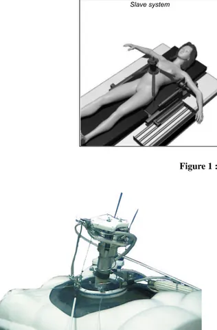
The tele-operated TER system allows the expert physician to move by hand a virtual probe in a natural and unconstrained way and safely reproduce this motion on the distant robotic site where the patient is. Then, mainly based on the echographic images and force information he re-ceives back, the expert operator can move the virtual probe to control the real one, see Figure 1. The real probe is placed on the slave robot end-effector (see figure 2). Posi-tion and force informaPosi-tion are transmitted bi-direcPosi-tionally (together with live visual and audio). The slave robot ex-ecutes the orders sent from the master site. A non-expert operator is located close to the patient and supervises the procedure that he can interrupt. The patient can at any time communicate with him or with the expert. From clinician side, the haptic control station is developed to give more realistic environment and finer command of what remotely occurs, it integrates a PHANToM device (from SensAble Device Inc) which has 6 degrees of freedom (dof) and ren-ders 3D-force information. Position and orientation track-1
Slave system Network Master system Audio flow Video flow Robot Information Ultrasound images Doppler Haptic flow
Figure 1 : TER system overview
Figure 2 : TER slave robot
ing of the virtual probe is performed within a workspace of 16cmx13cmx13cm and with maximum a force of 6.4N. Real time force feedback information and a virtual geomet-ric model of the patient are rendered to the expert operator. From patient side, the slave robot is remotely controlled by the medical expert, who handles his virtual probe via the force feedback robot. The precise position of the ul-trasound probe is provided by an optical localizer and is sent to the master site where the position is represented as a visual information. Two IDSN 128kb/s connections are used; one is for the Visio-phonic data and echographic im-ages and the other one is for the transmission of the control information for the slave-robot.
3. Risk Analysis
3.1 Terminology
Risk management can be guaranteed only if the terminol-ogy is stable and non ambiguous. In the safety analysis field, different notions are often used and can have different definitions. Based on recent medical norms and on safety critical system terminology we propose to apply them to the medical robotics field.
Harm and risk
Both in generic and medical norms as CEI 300-3-9 [11], Guide 51 [13] and ISO 14971 [12], a harm is defined as a
physical injury or damage to the health of people, or dam-age to property or the environment. A harm can be defined
by its gravity (minor, major, sever, etc.) and its probability of occurrence. Then, risk is defined as the combination of
the probability of occurrence of harm and the severity of the harm.
Hazard and hazardous situation
In order to describe how accidents appear, the term hazard is used as an anterior notion i.e. a hazard may result in an accident. For industrial robotics, hazard was defined as an energy transfer [18], which is similar to MORT (Man-agement Oversight and Risk Tree) [15]. Leveson [21] de-fine hazard as "a state or set of condition of a system that, together with other conditions in the environment of the system, will lead inevitably to an accident". To cope with those different points of view we chose to use the more generic definition of the Guide51 [13]: a hazard is a
po-tential source of harm. For instance, a sharp edge may be
defined as a hazard, it will not necessary produce a harm, it depends on the situation. Therefore, a hazardous situation is a circumstance in which people, property or the
environ-ment are exposed to one or more hazards. This notion can
be compared to the Leveson’s definition of hazard.
Risk management and risk analysis
According to the most recent medical and generic norms [12, 13], Risk management is the term for all the process including:
• Risk analysis: system definition, hazard identification and risk estimation
• Risk evaluation: procedure based on the risk anal-ysis to determine wether the tolerable risk has been achieved
• Risk control: procedure based on the two previous ac-tivity in which protective measures are chosen and im-plemented in order to reduce risks.
Risk assessment is also used to express risk analysis and
risk evaluation. In the previous norm on risk management EN 1441 (1997) [8], the generic term was risk analysis for the whole process. In the new terminology, risk analysis is the core of the risk management, therefore we focus on this activity in this paper.
3.2 TER slave control system definition
The first step of a risk analysis concerns the definition and the descriptions of the system, its boundaries and the in-tended use. This step is particularly linked with require-ments analysis and human factors integration. We focus on two main activities of human factors engineering: the func-tion allocafunc-tion and the task analysis. The funcfunc-tion alloca-tion aims at determining the distribualloca-tion of work between human actors and machines. It is particularly important to define non ambiguous and consistent tasks for humans who are using the robot. Task analysis is conducted to identify the details of specified tasks, including the required knowl-edge, skills, attitudes, and personal characteristics required for successful task performance.These activities are usually performed with different algorithms. The allocation should be iterative and can follow algorithms as in [20, pp.231-236], [1] and [22]. Through this description of function allocation, modeling furnish basis for task analysis. One of the difficulties is to model those allocations and to integrate them to system modeling. The purpose of this section is not to present al-gorithms for those activities, but to study how UML help in modelling the specification of the function allocation and the definition of task analysis.
General Scenario
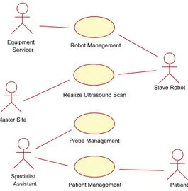
The first step is to describe the general scenario of the ap-plication to determine system functions. The UML use
case diagram in figure 3 presents the main use cases during
an ultrasound scan examination. This diagram belongs to the business modelling (as defined in [14]). The business is here the real ultrasound scan examination. The busi-ness modelling permits to increase the understanding of the business and facilitate communication about the busi-ness [9], particularly between engineers and doctors. Based on this diagram, the TER system is later integrated in the requirement modelling in the next diagrams. In the TER project, experts have studied the ultrasound scan examina-tion and particularly the use case Realize Ultrasound Scan, to determine all the interactions between the doctor ma-nipulating the probe, and the patient (particularly pressures and movements on the patient’s body which are critical for safety). This leads to the choice of a parallel robot ture (Cf. fig.1) which is different from a serial robot
struc-Patient Diagnose Realize Ultrasound Scan
Patient Management Probe Management Specialist
Figure 3 : Use case diagram of the business ultrasound scan
ex-amination
ture (like a robot arm). The main safety criteria was to limit the work envelope and limit the collisions (which are well-known with robot arms). The difficulty of modelling the work space (the patient’s body), leads to the choice of a compliant slave robot, with an actuation by intrinsically compliant artificial muscles [27]. The other use cases have also be studied to determine the architecture of the TER system. For example, the use case Patient Management, contains scenarios of communication between the patient and the medical expert which are essential. This led to choose a bi-directionally visioconference subsystem.
From actual echography to robotic echography
First UML diagrams (use case and object diagrams) show all the interactions between actors and the system, but also between actors themselves. An actor characterizes an out-side user or related set of users who interact with the sys-tem [2]. It is possible for an actor to be a human user (like in figure 3) or an external system. This is really use-ful in socio-technical systems, and particularly in the TER project. Indeed, such a modelling allows the interactions to be handled for safety studies. We choose to represent two external systems as actors: the Master Site and the Robot. The Master Site replaces the actor Specialist (Cf. fig. 3) who is in the charge of realizing the examination.
The use case diagram presented on figure 4 shows the TER slave site in a business modelling view. This model shows a first allocation of tasks between actors according to the medical domain. Tasks can be described with
col-laboration or sequence diagrams for each use case.
How-ever, on this diagram, the boundaries of the computer con-trol system are not defined. We defined the TER Concon-trol
System as all the machine parts (computer control system,
actuators, sensors, monitors, etc.) but without the physical structure of the robot. In order to specify requirements, it is important to define whether each use case belongs to the system or not. For example, the use case Robot
Manage-ment includes tasks such as maintenance operations. This
fault prevention operation (preventive maintenance) can be entirely independent of the TER system or may be assisted by the system (for example by monitoring the use time of
Realize Ultrasound Scan
Specialist
Assistant Patient Management Probe Management Patient Robot Management Master Site Equipment Servicer Slave Robot
Figure 4 : Use case diagram of the TER slave site
TER Control System
Operator
Patient Management Robot Management
Install / Init Control System <<include>> Calibrate Controller <<include>> <<include>> Patient Master Site
Realize Ultrasound Scan
Slave Robot
Figure 5 : Use case diagram with control system boundaries critical units). Patient Management is a set of scenarios that can be clean patient, position patient, or monitor pa-tient during operation. These use cases imply a collabo-ration between cognitive ergonomists, medical specialists and requirement engineers to determine, for each task, how the system can help the actors to perform the task, make decisions, diagnose or act. Again the models have to be understood by all the participants of the development pro-cess (analysts, designers, etc.).
TER slave control system boundaries
The determination of the system boundaries is a funda-mental step of requirements analysis, and is entirely linked with the definition of human tasks. In this step, it should be determined which of the requirements are system re-quirements, which are requirements for the operational pro-cesses associated with the system and which requirements should be outside the scope of the system [26]. Based on figure 4, we have chosen use cases that belong to the computer control system for the TER slave robot. Figure
Specialist Assistant Equipment Servicer TER control system Slave robot Patient Move probe on Operator Installing, monitoring
Figure 6 : Class diagram in a business modeling 5 models the computer control system use cases where a new actor is specified in the class diagram presented in fig-ure 6: Operator inherits from the Equipment Servicer and the Specialist Assistant. Some previous use cases as
Vi-sioconference Management (not shown for readability) and Probe Management have been removed from this use case
diagram (fig. 5) because they don’t belong to or have any interaction with the computer control system.
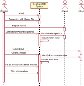
On sequence diagram presented in figure 7, the main scenario of the installation of the whole system is pre-sented. We present this diagram because most of the in-teractions between human and technology appear during this scenario (during the use case Realize ultrasound scan, human tasks are less numerous). Such diagram help in de-scribe tasks that humans have to do. For instance the
Oper-ator has to Prepare Patient, which can be extend in position
the patient, put ultrasound scan gel on patient’s body, give information to the patient, monitor the patient, etc. There-fore, this diagram and some refinements help in represents all the tasks.
This modelling of tasks is also useful to determine a sequence of actions, which can be essential for safety. Indeed, the sequence of actions presented on figure 7 has been determined according to functional requirements and safety requirements. For instance, Connection with master
site has been placed before all the installation procedures
in order to minimize the waiting time (connection can be long) of the patient with the robot placed on her/his body (that can create a psychological trouble). Another exam-ple is the action Set air pressure in artificial muscles com-ing after all installations and calibrations. Without any air pressure in artificial muscles, the robot system is safe and all the installations and checks can be done safely.
On the same diagram it is also important to study in-terlocks between tasks. The calibration of the controller depends on the patient corpulence, and this factor influence also the robot settings (for example the length of the ca-bles connected from muscles to the slave robot, see figure 1). Hence, it is important to calibrate the controller, first
: Operator
: TER Control System
: Patient : Robot
Prepare Patient Calibrate for Patient corpulence
Identify Patient position
Identify Robot configuration Calibrate Robot
Calculate Patient model
Calculate Robot model Install
Set air pressure in artificial muscles
Start teleoperation Install Robot Connection with Master Site
Figure 7 : Sequence diagram of installation of the whole system according to the patient body, and then to the robot set-tings. The order of those actions presented with sequence diagram is easily readable by non expert modelling.
These models which are essential in a safety critical project, can directly be used for different safety-dependent tasks: writing of a user-guide (using the sequence dia-grams), specification and design of the Human-Machine Interface (HMI) and furnish models for the specification of the system. It is important to note that in such robot systems, HMI includes the robot-human interface (control panels, teach pendant, computers, etc.) but also the robot itself (in the TER project the slave robot is always in con-tact with the patient’s body).
3.3 Hazard identification and risk evaluation
with analytical methods
In order to perform the risk analysis, engineers use several analytical methods. We have chosen to use both FMECA (Failure Modes and Effects Criticality Analysis) and FTA (Fault Tree Analysis), because of their complementarity (a forward and a backward analysis) and expressiveness (in-tegration of software, hardware units or human failures). They are also widely used in robotics [6, 16, 29] and rec-ommended in both critical systems [21] and norms [11, 12]. An important point which is rarely developed in those techniques, is the human error analysis. Indeed, this field has been studied for years in cognitive sciences, but the notion is still rare in risk management norms. Neverthe-less, it is often noted that human error can be integrated in techniques as FMECA and FTA. A first part of this sec-tion deals with human error, its identificasec-tion and analysis with UML modelling. Then, we present some results of our study with FMECA. In order to be concise we don’t present any diagram of FTA. This work is still in progress and we
Interface design proposals Scenarios from use
cases Human error and performance models Elaborate scenarios description Human error identification New requirements & re-design & documentation Human
error analysis
System definition assessmentRisk Risk control
Figure 8 : Structure of human error analysis method don’t have enough results on relationships between FTA and UML. We also don’t present the hazard tables which must be done during hazard identification step. Moreover, we focus on risk evaluation, taking account that a complete presentation of all the models and all the results is impos-sible in an paper.
3.3.1 Human error analysis
Human error can be defined as a failure of a human to do
a specified action, which results in undesirable outcomes. The aim of this activity is to reduce the undesirable actions, their propagation and their outcomes. It leads to the speci-fication of new requirements, re-design and documentation production. The complexity of human error classification and cognitive theory [24] usually lead to the use of design checklists and guidelines [21]. Human error analysis meth-ods are also often based on experimentation, simulation, and on human reliability analysis [17]. But for innovative projects, it is really difficult to get information on experi-ence, incident and accident reports. Moreover, guidelines are not sufficient for new projects as medical robots [30]. For instance, we found nothing on medical robots. Thus, we had to develop our own accident scenarios. We notice that a human error is linked with a use case because it ap-pears during a scenario of use. So the description of the error can be modelled with a sequence diagram. It is a sce-nario of a use case with an erroneous message generated by a human actor. Then, a number of models, theories and collections of empirical data about human performance and human error can be useful in deciding which scenarios it will be important to analyze [25]. This analysis process is presented in figure 8 adapted from THEA [23], a method for human error analysis.
A first analysis can be based on the business mod-els and then on the requirement modmod-els (as explained pre-viously). The business modelling leads to identify er-rors linked with social interaction whereas the requirement modelling identifies errors during the use of the system, di-rectly linked with human-machine interfaces. For instance, based on the sequence diagram in figure 7, different errors can be identified:
• Omission, non execution of an expected action: the operator forget to do Connection with master site • Action performance error:
– Bad execution of an expected action: the
opera-tor place the patient in a wrong position
– Execution of an action at a wrong instant: the
operator do the Set the air pressure in artificial
muscles before position patient
– Execution of several actions in a wrong
se-quence: the operator can change the order of the installation and calibration.
• Unknown or unplanned actions: the patient try to catch the robot.
For each identified error it is possible to describe the sce-nario with a sequence diagram but also to describe effects and to present corrective measures (interlocks, checks, use modification, etc.).
Later, for each HMI proposal, all the potential errors have to be analyzed in the same way. In the TER project, the operator is in charge of calibrating the robot controller in order to calculate robot and patient models (cf. fig. 7). The proposal interface for this scenario is the use of a 3-D position sensor manipulated by the operator. The use of such an interface can produce errors. Based on the se-quence diagram, we can determine for each message how it is possible to reduce errors (supervision of the system and validation of the calculated models) and also produce a documentation for the procedure. This is detailed with UML diagram in part 3.3.2. For the TER system, there are three main HMI on the slave site: a computer, a power con-trol panel and the robot itself. The human error analysis has to consider how the human can fail in interacting with those HMI during a use case scenario. For example, it is impor-tant to identify what will happen if the operator pushes the wrong button during a use case. Again, this implies the use of sequence diagrams. In order to identify scenarios and system responses to the errors, it is useful to use a state
di-agram (Harel’s statecharts) to model the external black box
behavior to indicate in which state the system is when the error happens.
As presented here, it is possible to describe human er-ror with sequence diagrams. But today there isn’t any tools to integrate errors in the UML models, the description re-mains qualitative. Moreover, during requirements analysis, models are not enough refined to identify the error propa-gation. This can be done later, and particularly during risk management activities. Indeed during risk analysis, fail-ures and their effects are analyzed. And it is possible to integrate human errors in techniques as Failure Modes Ef-fects and Critically Analysis and Fault Tree Analysis.
3.3.2 Failure Modes Effects and Critically
Analysis (FMECA)
FMECA is a method used for the identification of poten-tial errors (failure modes) of the examined object (sys-tem, segment, software/hardware unit) in order to define and classify their effects (failures) with regard to criticality
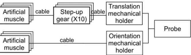
Artificial muscle Translation mechanical holder Orientation mechanical holder Probe cable cable Artificial muscle Artificial muscle Artificial muscle Step-up gear (X10) Step-up gear (X10) cable
Figure 9 : Main mechanical units of the slave robot (see fig. 2) (also called Failure Modes, Effects and Criticality Analy-sis). This is to prevent faults (causes of failure) and thus weak points in the design which might result in harm. Sec-ondly, the FMECA is also to furnish results for corrective measures, and for the determination of operating and ap-plication conditions of the system. Each failure mode (the way the component fails) is analyzed, and effects on the system are assessed. This analysis should lead to hazards previously identified. Several models are necessary to per-form this study, and each designer has to provide models from his domain: electronic, electrical, computer and me-chanical. It is also possible to analyze human error. A FMECA is appropriate when the analysis has progressed to the point where hardware and software items may be eas-ily identified in UML diagrams. Therefore, UML diagrams presented here belong to the analysis model (whereas pre-vious diagrams were requirement diagrams).
Mechanical component analysis
It is possible to perform a risk analysis on mechanical units based on block diagrams or other mechanical notations. There isn’t any UML diagram that can be directly used for mechanical notation. However, it is possible to represent units with object diagrams. Figure 9 represents the main physical units of the slave robot with an UML object di-agram (similar in this form to a block didi-agram). Based on this diagram it is possible to perform a FMECA. For instance, in figure 10, we can identify two failure modes for an artificial muscle. For risk evaluation, we have used a classic table, that permits to perform a qualitative eval-uation. Severity, expresses the fact that the failure effect can have a high level (1 is for death or serious harm) or a low level (3 is for no harm). Occurrence has five lev-els from I (improbable) to F (frequent). Risk is the prod-uct or those two code. Then, during risk evaluation, each risk code is analyzed in order to decide if the risk is ac-ceptable. Important points are highlighted during FMECA. For instance, we had to determine the occurrence of failure modes (more than one time per year for Muscle pierced and never for Breaking), the decrease of pressure for Muscle
pierced (at least a decrease of 0.6 Bar from a control
com-mand of 1 Bar), and life cycle of artificial muscles (still in study). In the last column, the Action required point means that the air pressure has to be removed from all the artifi-cial muscles. In this case, the state of the TER slave robot is changed. This is modelled with a state diagram as in fig-ure 11. Based on this diagram it is possible to represent all
Component / Function A. Local effect B. Effect on system Risk
estimation A. Failure detection method B. Action required C. Other Failure cause Failure mode Occurrence Severity Risk Artificial Muscle Pierced - Abrasion of inner tube - Bad maintenance - Bad use A. Decrease of air pressure B. Increase of length, decrease of pressure on the patient A. Pressure sensor B. Cut off the air pressure F 3 F3 Breacking Wear of muscle outer cover A. No physical constraints B. Patient struck by a moving part A. Length sensor B. Protection device around muscles or emergency stop I 1 I1
Figure 10 : Example of a FMECA table for a mechanical unit
Active Motion
control IDLE
Verification do/ Repair
entry/ Remove air pressure
End of use Motion
control IDLE
Verification do/ Repair
entry/ Remove air pressure
End of use
Repair is impossible
Stop examination
Start motion control
Muscle failure
Stop motion control
End of repairing
Emergency Stop entry/ Shut down power
Emergency stop pushed
/ remove patient
Figure 11 : Reduced state diagram
the states but also the events causing a state transition. In case of Failure of a muscle (see fig. 11), the system changes in state Verification. If it is impossible to easily re-pair, this means that the examination must be stopped (End
of use state). Another important state is the emergency
stop. This state can be reached by any other states dur-ing use of TER (modelled as Active state). The transition only depends on the Operator, he must push an emergency button. By definition emergency stop cannot be a software measure, this condition was the same for industrial robots. In our case, if power (air and electricity) is removed from TER control system, the muscle length increases and then the pressure on patient decreases to zero.
Electronic components analysis
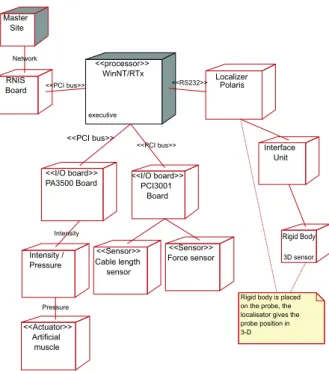
Figure 12 illustrates a part of the electronic components of the slave TER control system with a deployment diagram. Electric parts can also be integrated in this diagram. Based on this diagram it is possible to specify for each
stereo-type (a well known component who belongs to a class of
devices, as a «sensor», an «actuator», etc.) a set of fail-ure modes. For instance a «sensor» has failfail-ure modes as: frozen, biased, run-away, or spike. Therefore, it is possible to associate UML stereotype to failure modes for FMECA. We present the analysis of failure modes of the control sys-tem processor (WinNT/RTx) in figure 13. Those two fail-ure modes can be both controlled with well-known safety patterns. First, a Random output, can be controlled with a
WinNT/RTx executive <<processor>> Localizer Polaris Interface Unit Rigid Body 3D sensor PA3500 Board <<I/O board>> PCI3001 Board <<I/O board>> Intensity /
Pressure Cable length sensor <<Sensor>> Force sensor <<Sensor>> Artificial muscle <<Actuator>> <<PCI bus>> <<PCI bus>> <<RS232>> RNIS
Board <<PCI bus>>
Pressure
Rigid body is placed on the probe, the localisator gives the probe position in 3-D Intensity Master Site Network
Figure 12 : Deployment diagram of the slave TER Control
Sys-tem Component / Function A. Local effect B. Effect on system Risk
estimation A. Failure detection method B. Action required C. Other Failure cause Failure mode Occurrence Severity Risk Processor WinNT/RTx Frozen Interlock in the program or in the OS A. No control data B. Frozen motion A. External system (Watchdog type) B. Reboot system after removing patient F 3 F2 Random output Memory overflow B. Uncontrolled motion A. Dual channel pattern B. Back recovery or reboot system R 1 R1
Watchdog Subsystem Stroke Stroke Stroke Timeout Reset Missed watchdog stroke Service period
Figure 14 : Sequence diagram: watchdog pattern from [7]
Pause do/ Connection entry/ Freeze robot Verification
do/ Repair
entry/ Remove air pressure
End of use Init IDLE Motion control do/ Control Connexion failure or delay exceeded Install patient, Connection, and calibrate Connestion established Connection cut Stop control Failure
/ place robot in initial position
Muscle failure
Stop examination
Start motion control
End of repairing
Repair is impossible
Figure 15 : State diagram of slave TER control system
dual channel for control as presented in [19]. In this case,
there is two control subsystems (also called channel1 and channel2) calculating command position values and a com-parison is then applied. This safety pattern can be modelled in UML and is presented in [7]. The other failure mode can be controlled with the use of a watchdog, described in fig-ure 14. As long as Subsystem requires service (Stroke mes-sage) to the Watchdog, nothing happens. This design mea-sure can be hardware or software. In our case, a possible action is to implement an external watchdog, i.e. an hard-ware device. This safety measure should be modelled in the deployment diagram in figure 12 (no represented here). Relationships between units must also be analyzed. Only represented with stereotypes (as «RS232») or comments (as
network), they can also failed. For instance, the control
sys-tem must change state in cause of network failure occurring during Motion control. The motion is frozen for a while un-til the connection is established. This is modelled in figure 15. New states have been added to the previous state dia-gram (see fig. 11. The Emergency stop is not represented in this diagram for readability but it nevertheless exists.
Software analysis
FMECA applied to software is still in study. Indeed, it is impossible to calculate the occurrence of a software error, and then to decide if the risk is acceptable. Therefore,
eval-Human Machine Interface TELEOP : Tele-operation GENE : trajectory generator Force Sensor I/O Boards Position sensor Motion Generator TELEOP Controller GENE Controller
Motion planner HMI Robot Model Localisator Patient Model Geometrical model Motion controller Actuator Sensor Position Controller
Figure 16 : Class diagram: main classes
Component / Function A. Local effect B. Effect on system Risk
estimation A. Failure detection method B. Action required C. Other Failure cause Failure mode Occurrence Severity Risk Position controller Unstable - external perturbation - Bad calculation
B. Curt motion, few fluidity C. Determine stability and robustness Spike - external perturbation - Bad calculation B. Uncontrolled motion, pressure on patient too high
A. Digital filter on command position value B. Ignore value
Figure 17 : FMECA table for the position controller
uation is performed by the designer, who decide to imple-ment fault tolerant mechanisms or not. A first way is to consider software as a component and to analyze only its outputs. In this case classical measures, as redundancy, polling systems, watchdog subsystems, etc, can be used to guarantee a risk reduction. But those solutions are not easy to implement because of complexity, time and cost. A second way can be an analysis of the software in several units. Based on class diagrams and on sequence diagram, it is then possible to identify some failure modes and their effects. FMECA in this case is useful to identify crit-ical units. For instance, the class Position controller (in figure 16) has to be studied in order to determine its robust-ness. The FMECA table in figure 17 illustrate this analysis. Some design choices can nevertheless be integrated in this analysis (as the Digital filter in the last column).
: Localizer : Operator : 3D sensor : Patient Model : HMI Start calibrate
patient model Create (number of points) Moves 3D sensor on patient body
Read 3D position Localize Read 3D position Read 3D position Localize Localize Calculate model
Show patient model 3D representation of
patient Validate
Moves 3D sensor on patient body
Moves 3D sensor on patient body ETC... Operator points a 3D
sensor on patient body. Localizer furnishes 3D position of the sensor. The model is calculated with a limited number of 3D points.
Figure 18 : Sequence diagram of the action "Calibrate for patient corpulence" (see fig.7)
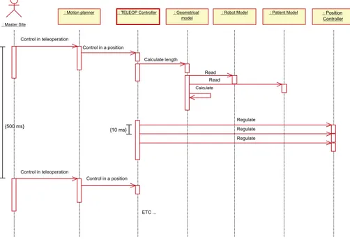
: Master Site
: Geometrical model
: Robot Model : Patient Model : Position Controller
: Motion planner : TELEOP Controller
Read Read Calculate length Regulate Regulate Control in teleoperation Control in a position Control in teleoperation Control in a position Regulate {10 ms} ETC ... Calculate {500 ms}
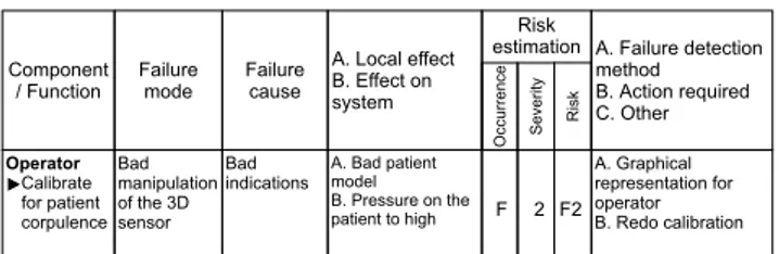
Component / Function A. Local effect B. Effect on system Risk
estimation A. Failure detection method B. Action required C. Other Failure cause Failure mode Occurrence Severity Risk Operator Bad manipulation of the 3D sensor Bad indications A. Bad patient model B. Pressure on the patient to high A. B. Redo calibration Graphical representation for operator Calibrate for patient corpulence F 2 F2
Figure 20 : Human failure for "Calibrate for patient corpulence"
Human component analysis
Human errors can be identified as exposed previously in section 3.3.1. In figure 18 we have refined the message
Calibrate for patient corpulence represented on sequence
diagram in figure 7. An error that can be identified, is a re-alization error (bad manipulation of the 3D sensor), noted as a failure mode. In this case, the object Patient model is wrong. And we can see on the figure 19, that this model is used in order to calculate the Geometrical model. Then, it will produce a bad regulation of the robot position. In order to limit this error, the operator must have the possibility to stop calibration and to do it again. We have not represented this scenario, but it can be easily done with sequence dia-gram. The table of figure 20, illustrates this analysis. An action is here to let the operator to decide if the model is correct or not by a validation step (last column).
4. Conclusion
Medical robots belong today to safety critical systems. Therefore, their development process must include a risk management activity. Risk analysis is described in medi-cal and generic norms as the core of this activity. We have used this technique to the TER project, with two contribu-tions. First the integration of human factors in risk analysis is not obvious and still in study. Second, we proposed to use UML as the language for the requirements and analysis modelling.
In the robotics field, and particularly for medical robots, UML can be useful to model requirements integrat-ing human factors. Activities as task analysis and function allocation, which are critical for safety, depend on commu-nication between engineers, doctors, or any other actors. UML, as an human centered language, and with its graph-ical notation is really useful for those activities. UML can also model several fields as electronics and computer sci-ence. Nevertheless, mechanical modelling is hardly per-formed. An important point, is that this notation can be used from requirements to design. This permits to guar-antee a complete and consistent modelling from requiments to design, and particularly for medical specific re-quirements. UML models, in an object-oriented modelling, can also be used in an FMECA, even if this technique was first used with functional models.
Following the method presented in this paper, the number of diagram can quickly increase and it is
impor-tant to decide which ones are the most imporimpor-tant for safety. This can only be done if the analyst knows UML notation. But UML has now became a standard for system defini-tion and more and more analysts use it. For a risk analysis, UML diagram don’t provide any tools or guidelines in or-der to identify failure propagation on objects and effects on the system. We performed this analysis qualitatively by in-terpreting sequence and state diagrams. FMECA is useful to determine component failure effects, but don’t analyze failure and events interactions as Fault Tree Analysis does it. We are still studying how FTA can be useful for those tasks based on UML diagrams.
Finally, we can say that such an analysis is mostly qualitative. The main problem is that it is difficult to quan-tify probability of a failure or an event. Risk is often eval-uated with qualitative metrics. This is particularly true for software analysis, where it is impossible to evaluate any failure rate. This led to a different approach; instead of controlling risk of a system, it is now experimented to con-trol the manner the system was produced, i.e. to concon-trol the development process. This paper is closed to this concept. Moreover, certification, which is an important concern for today medical robots, is based on the same principle. A further work consists in complete our safety analysis, but also to study how our results can contribute to a certifica-tion process for medical robots.
Acknowledgements
This project is supported by the French Ministry of Re-search and Technology (action line "ACI Telemédecine"), by France Telecom R&D and by UAEM/CONACyT.
References
[1] D. Beevis, R. Bost, B. Döring, E. Nordø, F. Ober-man, J-P. Papin, H. Schuffel, and D. Streets. Analy-sis techniques for man-machine system design. Tech-nical Report AC/243(Panel 8)TR/7, NATO, Canada, 1994.
[2] G. Booch, J. Rumbaugh, and I. Jacobson. Unified
Modeling Language Users Guide. Addison Wesley
Longman, 1999.
[3] M. Carey. Proposed framework for addressing human factors in IEC 61508. Technical Report 373/2001, Health and Safety Executive, UK, 2001. http://www.hsebooks.co.uk.
[4] L. Caroll, B. Tondu, C. Baron, and J.C. Geffroy. Comparison of two significant development methods applied to the design of real-time robot controllers.
IEEE International Conference on Systems, Man and Cybernetics (SMC’98), pages 3394–3399, October
[5] B.S. Dhillon. Robot Reliability and Safety. Springer-Verlag, 1991.
[6] B.S. Dhillon and A.R.M. Fashandi. Safety and reli-ability assessment techniques in robotics. Robotica, 15:701–708, 1997.
[7] B.P. Douglass. Doing Hard time : developping
real-time systems with UML, objects, framewoks and pat-terns. Object technology. Addison-Wesley, 1999.
[8] EN 1441. Medical devices - risk analysis. CEN, Eu-ropean Committee for standardization, 1997. [9] H.E. Eriksson and M. Penker. Business Modeling
with UML: business patterns at work. John Wiley
and Sons, Inc., 2000.
[10] Food and Drug Administration. Medical device use-safety: incorporating human factors engineer-ing into risk management. Technical report, U.S. Departement of Health and Human Service, 2000. http://www.fda.gov/cdrh/humfac/1497.pdf.
[11] IEC 60300-3-9. Dependability management - part 3: application guide - section 9: risk analysis of techno-logical systems. International Electrotechnical Com-mission, 1995.
[12] ISO 14971. Medical devices - Application of risk management to medical devices. International Orga-nization for Standardization, 2000.
[13] ISO/IEC Guide 51. Safety aspects - Guidelines for their inclusion in standards. International Organiza-tion for StandardizaOrganiza-tion, 1999.
[14] I. Jacobson, G. Booch, and J. Rumbaugh. The
Uni-fied Software Development Process. Addison Wesley
Longman, 1999.
[15] W. Johnson. MORT safety assurance systems. Deker, Marcel Incorporated, New York, 1980.
[16] K. Khodabandehloo. Analyses of robot systems using fault and event trees: case studies. Reliability
Engi-neering and System Safety, 53:247–264, 1996.
[17] B. Kirwan. Human error identification in human re-liability assessment. Part I: Overview of approaches.
Applied Ergonomics, 23(5):299–318, 1997.
[18] H. Kumamoto, Y. Soto, and K. Inoue. Hazard identifi-cation and safety assessment of human-robot systems.
Engineering Risk and Hazard Assessment, 1:61–80,
1986.
[19] U. Laible, T. Bürger, and G. Pritschow. A fail-safe dual channel robot control for surgery appli-cations. Proceedings of SAFECOMP01,
Springer-Verlag Berlin Heidelberg, pages 75–85, 2001.
[20] J-C. Laprie, J. Arlat, J-P. Blanquart, A. Costes, Y. Crouzet, Y. Deswarte, J-C. Fabre, H. Guiller-main, M. Kaâniche, K. Kanoun, C. Mazet, D. Powell, C. Rabéjac, and P. Thévenod. Dependability
hand-book (in French). Cépaduès - Éditions, Toulouse,
France, 1995.
[21] N.G. Leveson. Safeware - System safety and
comput-ers. Addison-Wesley, Univesity of Washington, 1995.
[22] M. Mersiol, C. Mazet, H. Guillerman, and H. Waese-lynck. Human dependability in complex system: an issue of task consistency and task allocation.
Interna-tional Conference on Probabilistic Safety Assessment and Management (PSAM’4), 4:2693–2698,
Septem-ber 1998.
[23] S. Pocock, B. Fields, M. Harrison, and P. Wright. THEA - A reference guide. Technical Report 336, University of York Computer Science, 2001. http://www.cs.york.ac.uk/ftpdir/reports/.
[24] J. Reason. Human Error. Cambridge University Press, Cambridge, 1990.
[25] J. Rushby. Modeling the human in human factors.
SAFECOMP01, pages 86–91, 2001.
[26] I. Sommervile and P. Sawyer. Requirements
engineer-ing : a good practice guide. John Wiley and Sons,
Inc., 1997.
[27] B. Tondu and P. Lopez. Modeling and control of McKibben artificial muscle robot actuators. IEEE
Control Systems, 20(2):15–38, 2000.
[28] A. Vilchis, P. Cinquin, J. Troccaz, A. Guerraz, B. Hennion, F. Pellissier, P. Thorel, F. Courreges, A. Gourdon, G. Poisson, P. Vieyres, P. Caron, O. Mérigeaux, L. Urbain, C. Daimo, S. Lavallée, P. Arbeille, M. Althuser, J-M. Ayoubi, B. Tondu, and S. Ippolito. TER: a system for Robotic Tele-Echography. Lectures Notes in Computer Science,
Medical Image Computing and Computer-Assisted Intervention (MICCAI’01), pages 326–334, 2001.
[29] I. Walker and J. Cavallero. Failure mode analysis for a hazardous waste clean-up manipulator. Reliability
Engineering and System Safety, 53:277–290, 1996.
[30] P. Wright, B. Fields, and M. Harrison. Deriving human-error tolerance requirements from tasks. IEEE
International Conference on Requirements Engineer-ing (ICRE’94), 1:462–467, 1994.

![Figure 14 : Sequence diagram: watchdog pattern from [7]](https://thumb-eu.123doks.com/thumbv2/123doknet/2354558.37215/9.892.497.825.81.480/figure-sequence-diagram-watchdog-pattern.webp)