HAL Id: hal-00953008
https://hal.archives-ouvertes.fr/hal-00953008
Submitted on 28 Feb 2014
HAL is a multi-disciplinary open access
archive for the deposit and dissemination of
sci-entific research documents, whether they are
pub-lished or not. The documents may come from
teaching and research institutions in France or
abroad, or from public or private research centers.
L’archive ouverte pluridisciplinaire HAL, est
destinée au dépôt et à la diffusion de documents
scientifiques de niveau recherche, publiés ou non,
émanant des établissements d’enseignement et de
recherche français ou étrangers, des laboratoires
publics ou privés.
Antennas
Jonathan Bor, Olivier Lafond, Hervé Merlet, Philippe Le Bars, Mohamed
Himdi
To cite this version:
Jonathan Bor, Olivier Lafond, Hervé Merlet, Philippe Le Bars, Mohamed Himdi. Technological
Process to Control the Foam Dielectric Constant Application to Microwave Components and
Anten-nas. IEEE Transactions on Components, Packaging and Manufacturing Technology. Part A,
Man-ufacturing Technology, Institute of Electrical and Electronics Engineers (IEEE), 2014, 99, in press.
�10.1109/TCPMT.2013.2294871�. �hal-00953008�
Abstract—A technological process to control the foam
dielectric constant, an important issue for the design of microwave components and antennas, is described. For that purpose, the use of different commercial foam materials has been considered. This kind of foam substrate is made of original material (PVC, resin, …) into which gas is injected. So the dielectric constant of such foam is close to 1. It can be increased by expelling the gas out of the foam material. The authors are presenting the technological process used to expel the gas by pressing a foam slab at relatively low temperature (90°C). Thanks to this technological process, the dielectric constant variation can be controlled by the ratio between the initial and final slab thickness. It holds a great interest for the design of microwave antennas and circuits. Indeed, the dielectric constant inside gradient index lenses (Luneburg, Maxwell fish-eye and Fresnel lenses) must follow a particular law to obtain the desired radiation capabilities. Results of materials characterization are presented to validate the technological process. Foam based antennas and components are also shown to illustrate the interest of the process.
Index Terms— Foam material, controlled dielectric constant.
I. INTRODUCTION
ATERIALS with controllable permittivity are mainly used for electromagnetism and chemistry. Foam and composite materials exist with different dielectric constants [1, 2]. They can be used as a support or directly to design microwave circuits or antennas [3]. The foam material used in [3] has the particularity to offer low dielectric constant (close to 1). This allows for the designing of antennas with high efficiency. This kind of foam is composed of basic initial PVC material into which air is injected or special gas. In microwave applications, substrate integrated non radiative waveguides can be manufactured with a particular dielectric constant material [4]. In such applications, it could be interesting to adjust the dielectric constant for different waveguides and so to design phase shifters for example. In microwaves, antennas with inhomogeneous lenses can be designed to focus the radiation pattern [5] [6] [7] but such lenses (Fresnel-zone plate lens, Luneburg lens, Maxwell fish-eye lens and Rotman lens)
require the use of materials with different dielectric constant. For this kind of lens, the objective is to simplify the manufacturing and to reduce the cost by using only one material with controlled dielectric constant. The authors investigate a new and simple technological process to control the dielectric constant of a basic foam material. By expelling the gas contained inside a foam slab, the dielectric constant can vary, for example, between 1.3 and 3.2.
In the first part, the technological process is related in details. In the second part, the measurement setup of dielectric constant is presented and results are shown to validate the principle of controlled dielectric constant based on one initial foam material. These experimental results are compared with theoretical data allowing to predict the dielectric constant of the manufactured material. In the third part, several applications at 60 GHz are presented.
II. TECHNOLOGICAL PROCESS
Four different foams are used and tested to validate the technological process [8]. The first two kinds of foams (H200 and HCP50) are sold by Divinycell while the third and fourth ones (two different references of Airex PXc) are marketed by Corematerials.
A. Some instances of the foams used
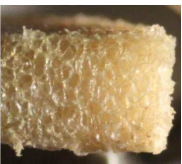
These materials have dielectric constants close to one because they are filled with small gas bubbles as it is shown in Figure 1 for the H200 foam. There is four kinds of foams feature low dielectric constant and loss, as presented in Table 1. These characteristics are obtained from a free space measurements setup which is depicted in the second part of the paper. Foams are closed-cell foams and are used for their mechanical properties in the field of construction.
TABLE 1
ELECTRICAL PROPERTIES OF THE FOUR FOAMS MEASURED AT 60GHZ
Foam type r tan
H200 1.23 0.005
HCP50 1.31 0.004
Airex PXc 245 1.31 0.010
Airex PXc 320 1.43 0.014
Technological Process to control the Foam
Dielectric Constant
Application to microwave components and
antennas
J. Bor, O. Lafond, Member, IEEE, H. Merlet, P. Le Bars, Member, IEEE, and M. Himdi
Fig. 1. Cross sectional photograph of a 5mm thick H200 Divinycell Foam.
B. The main idea
In order to determine permittivity of a foam sample, several parameters are involved:
- Density: ρx
- Permittivity: x
- Volume: Vx
- Thickness: hx
Where x can be replaced by the appropriate material: g for the gas (air for us), p for the polymer, fi for the initial foam, ff for the final foam.
Two different theories are reviewed: Knott and Plonus theories. The first one used the density and permittivity while the second one is based on the permittivity and volume. Both are computed and compared to measurements.
Firstly, the foam dielectric constant can be predicted by
Knott‟s formula [9]:
(1) Where f is the foam dielectric constant, p is the dielectric
constant of the base polymer, g is the dielectric constant of
the blowing agent gas (air in our case), and α is the volumetric fraction of polymer in the foam given by:
(2) The foam density depends on its volume:
(3)
Then the main and innovative idea for microwave antennas is to reduce the height of the foam by pressing it (without altering the foam surface area S). When being pressed (Figure 2), the gas is expelled out of the foam, thus increasing the density and the dielectric constant of the foam. The density of the base polymer does not change during the process.
The density ratio between the initial foam height hi and the
final height hf is given by:
(4)
(5)
Secondly, as mentioned in [10], knowing the volume ratio, we can calculate the effective relative dielectric constant of pressed foam by (6):
(6) Where Vg and Vp are the volume of gas and polymer.
In the reference [10], Plonus finds the volume ratio of gas to base polymer in the foam as a function of foam density and uses this to determine the dielectric constant of the foam. The equation (7) gives the volume of gas to volume of the base polymer ratio in considered foam knowing the density of
base polymer (ρp) and gas (ρg).
(7)
In order to verify the accuracy of the formulas (1) and (6), we used to predict the dielectric constant of H and HCP Divinycell foam [1].
In order to determine the dielectric constant and density of the
base polymer ( p and ρp) of each foam material (unavailable
data‟s from manufacturers), the foam samples were powdered
(Figure 3a) before being pressed (Figure 3b) to make sure there would be no gas left inside it during measurement. It will thus determine the utmost permittivity and density that can be reached (permittivity of the mixture composed of only core materials without gas). Every references of H or HCP foam
(10, 20, 50, 100 …) are made of the same base polymer; the
only difference is the final density of the foam. - For the gas (air): ρg=1.2 kg/m3and g=1.
- For H200 foam, the base polymer is PVC material, we
measured: ρp=1600 kg/m3and p=3.0.
- For HCP50 foam, the base polymer is PVC material, we
measured: ρp=1500 kg/m3and p=2.92.
- For Airex PXc 245, the base polymer is glass-reinforced
urethane material, we measured: ρp=1075 kg/m3and p=2.8.
- For Airex PXc 320, the base polymer is the same as PXc
245, but we measured: ρp=1273 kg/m3and p=3.15.
(a) (b)
Fig. 3. Picture of the powdered foam (a) and pressed foam (b)
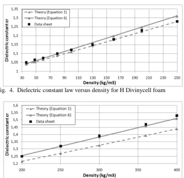
The formulas (1) and (6) compared to measurements of permittivity (10 GHz in the data sheet) show a good agreement. The measurements are made for different references of foams using the same base polymer but with different densities. Figure 4 and Figure 5 show this agreement
hi h
f
Pressure at T°
for both Divinycell foams (Airex does not present those values in their data sheet).
Fig. 4. Dielectric constant law versus density for H Divinycell foam
Fig. 5. Dielectric constant law versus density for HCP Divinycell foam
C. Pressing process
The first important parameter is the adjustment of the temperature during the pressing process. An optimized temperature compromise has to be determined in order to avoid melting and burning (with a too high temperature) or to avoid the sample to change size once pressure ceases (if temperature was not high enough). The optimized temperature depends on the type of foam material that is used. The second important parameter is the duration of the pressing. It can vary depending on the foam and will affect the stability of the foam. A sufficient pressing period is needed for the sample to keep its size after pressure. The temperature inside the whole sample of foam must be evenly spread.
For the four kinds of foams mentioned above, the samples are pressed during 20 minutes at 90°C.
A picture of a foam sample before and after being pressed is featured in Figure 6 and Figure 7. A stepped sample with different thicknesses has been pressed. In the figure 7, it is easy to see that the air bubbles have been expelled from the foam after pressing. The density of the foam material is higher after pressing because air has been expelled.
In the next section are presented the results of dielectric constant characterization for different initial thicknesses of foam and with the same final thickness (3mm).
Fig. 6. Stepped sample before being pressed (5, 10, 15mm).
Fig. 7. Stepped sample after being pressed at 5mm.
III. CHARACTERIZATION
A. Free space measurement setup
The measurement of dielectric constant is performed by using a free space measurement [11, 12] bench (Figure 8), composed of an ABmm Vector Network Analyzer (working between 8 GHz and 75 GHz) and a computer with software to extract the dielectric constant from measurements. The free space setup consists of two horns associated with two polyethylene biconvex lenses in order to obtain a focusing plane where the sample under test is placed. The computation of dielectric constant can be obtained either from reflexion (S11) or from transmission measurement (S21), the latter being used in this paper. Permittivity and loss tangent can be determined with formulas given in [13] and [14]. First, the bench is calibrated without any sample. Then, the same measurement is carried out with the sample under test and measurements results are computed in order to find out the dielectric constant of the sample.
This measurement process is fast but limited in terms of bandwidth by the size of the horns and lenses (from 46 GHz, up to 74 GHz). It also requires samples at least a few millimeters thick and with a diameter at least greater than five lambda. To ensure stable results, the whole band has to be measured and results are given at the middle frequency of the band (60 GHz here).
Fig. 8. Photograph of the free space measurement setup composed of horn-lens antennas and support of sample under test.
B. Experimental results of electrical properties
Measurements are done in the V band and electrical properties are given at 60 GHz. The foam samples have been pressed at 90°C during 20 minutes. The final thickness of samples is consistently 3mm after pressing. The four different foams have been characterized using the same method and results of pressed foam dielectric constant versus densities
II.b for all foam material.
Fig. 9. Dielectric constant law versus densities ratio for pressed H200 foam.
Fig. 10. Dielectric constant law versus densities ratio for pressed HCP50 foam
Fig. 11. Dielectric constant law versus densities ratio for pressed Airex PXc245 foam
Fig. 12. Dielectric constant law versus densities ratio for pressed Airex PXc320 foam
The results show that it is possible to increase the dielectric constant from 1.33 to 2.8 for the Airex PXc245 foam and 1.43 to 3.15 for the Airex PXc320. For the H200 foam, the range of dielectric constant is reached from 1.22 up to 2.35 and from 1.3 to 2.2 for the HCP50 foam.
In this section, applications on microwaves components and antennas are presented.
Several applications require a control of the dielectric constant. Non-radiative waveguide is a simple one. It is composed of a dielectric waveguide with two parallel metal plates above and below it. A 3dB/90° dielectric coupler has been manufactured at 30 GHz (Figure 13 and 14) with Airex PXc 245 and a permittivity of 2.1 inside the waveguide has been reached (after being pressed) while the dielectric constant is 1.33 outside of the waveguide.
Fig. 13. Dielectric coupler at 30 GHz before being pressed
Fig. 14. Dielectric coupler at 30 GHz after being pressed without Lens antennas are another example where dielectric constant must be control. Fresnel lens or metallic lens require several areas with fixed permittivities. Luneburg and Maxwell fish-eye lens require a gradient index inside the lens. A Luneburg lens has been manufactured at 60GHz as shown Figure 15. Inside the lens, the permittivity ranges from 1 to 2 (for a perfect lens) from the edge of the lens to the centre of the lens. It is made of 6 areas, one with a ring of Rohacell foam
( r1=1.05) and five areas made of one piece of foam ( r2=1.33, r3=1.46, r4=1.62, r5=1.77 and r6=1.92).
(a) (b)
Fig. 15. Foam lens before (a) and after (b) being pressed
V. CONCLUSION
A technological process to design foam material with controlled permittivity has been presented and validated by measurements. The process is simple, inexpensive and materials are lightweight. The permittivity range is limited by the core material properties.
Although four types of foams have been investigated, the proposed process is general.
This technology can be directly applied to the design of microwave components and antennas. It makes for instance the manufacturing of gradient index lenses much easier as detailed in a forthcoming publication.
ACKNOWLEDGMENT
The authors acknowledge L. Cronier, X. Morvan, X. Castel and C. Guitton from IETR de Rennes (France) for their support on mechanics.
REFERENCES [1] Divinycell, www.diabgroup.com.
[2] Airex Baltek, www.corematerials.3AComposites.com.
[3] S. Chainon, „‟Etude et conception d‟antennes composes de guides
d‟ondes en technologie mousse métallisée. Applications aux antennes à balayage électronique‟‟, Dissertation at the University of Rennes 1,
France, 2002.
[4] F. Xu, K. Wu, „‟Substrate Intergrated Nonradiative Dielectric
Waveguide Structures Direcly Fabricated on printed Circuit Boards and
εetallized Dielectric δayers,‟‟ IEEE Transactions on εicrowave
Theory and Techniques, Vol. 59, No 12, December 2011.
[5] H. D. Hristov, H. A. J. Herben, “εillimeter-wave Fersnel-zone plate
lens and antenna,” IEEE Transactions on εicrowave Theory and
Techniques, vol. 43, no. 12, Dec. 1995
[6] B. Fuchs, O. Lafond, S. Palud, L. Le Coq, M. Himdi, M. C. Buck and S.
Rondineau, „‟Comparative Design and Analysis of δuneburg and Half
Maxwell Fish-Eye δens Antennas,‟‟ IEEE Transactions on Antennas and Propagation, vol. 56, no. 9, Sept. 2008.
[7] δ. Schulwitz, A. εortazawi, “A new low loss Rotman lens design using
a graded dielectric substrate,” IEEE Transactions on εicrowave Theory
and Techniques, Vol. 56, No. 12, Dec. 2008.
[8] H. εerlet, P. δe Bars, O. δafond, ε. Himdi, “εanufacturing method of
a dielectric material and its application to millimeter-waves beam
forming antenna systems,” patent WO2013083794, June, 2013.
[9] E. F. Knott, “Dielectric constant of plastic foams,” IEEE Transactions on Antennas and Propagation, Vol. 41, No. 8, pp. 1167-1171, August 1993.
[10] ε. A. Plonus, “Theorical investigations of scattering from plastic
foams,” IEEE Transactions on Antennas and Propagation, Vol. 13, no. 1,
pp. 88-94, January 1965.
[11] G. L. Friedsam and E. M. Biebl, “A Broadband Free-Space Dielectric Properties Measurement System at Millimeter Wavelengths,” IEEE Transactions on instrumentation and Measurement, Vol. 46, No. 2, April, 1997.
[12] ABmm, www.abmillimetre.com.
[13] D. Bourreau, A. Péden and S. δe εaguer, “A Quasi-optical Free-Space Measurement Setup Without Time-Domain Gating for Material Characterization in the W-Band,” IEEE Transactions on Instrumentation and Measurement, Vol. 55, No. 6, December 2006.
[14] D. K. Ghodgaonkar, V. V. Varadan and V. K. Varadan, “Free-Space Measurement of Complex Permittivity and Complex Permeability of
εagnetic εaterials at εicrowave Frequencies,” IEEE Transactions on
Instrumentation and Measurement, Vol. 39, No. 2, April 1990.
Jonathan Bor was born May 10, 1987. He received the Electronics Engineering degree and French DEA (Masters) degree in signal processing and telecommunications from the Ecole Supérieure d'Ingénieurs de Rennes (ESIR), Rennes, France, in 2010, and is currently working toward a Ph.D. degree
in signal processing and telecommunications at the Institut
d‟Electronique et de Télécommunications de Rennes (IETR),
University of Rennes 1, Rennes, France. His research interests are millimeter-wave focusing and multibeam devices. His focus is on inhomogeneous lenses.
Olivier Lafond received his M. S. degree in radar and telecommunications from the University of Rennes, Rennes, France, in 1996, and the Ph.D. degree in
Signal Processing and
Telecommunications from the University of Rennes 1, Rennes, France, in 2000. Since October 2002, he has been an Associate Professor with the Institute of Electronics and Telecommunications of Rennes (IETR), University of Rennes 1. He has authored or coauthored of 25 journal papers and 50 papers in conference proceedings. He has also authored/coauthored three book chapters. He holds 6 patents in the area of antennas.
His research activities deal with passive and active millimeter-wave multilayer antennas and circuits, reconfigurable antennas, inhomogeneous lenses for shaping radiation patterns with active devices, imaging antenna systems.
Hervé Merlet was born in Angers, France. He received his Master's degree in electronic engineering from the University of Nantes, Nantes, France. In 1983, he joined the Research and Development laboratory of MATRA Communication, Quimper, France, where he contributed to the development of telecommunication terminals in
collaboration with the C.N.E.T. (Centre National d‟Etudes des
Télécommunications), Lannion, France. In 1994, he joined PHILIPS, Le Mans, France, as Staff Engineer to develop wireless technology and products. In 2001, he joined Canon Research France, Cesson, France, where he worked in the Network and Connectivity Department as Research Engineer. He holds more than 15 European patents. His current research interests are millimeter-wave antenna system and signal processing.
Philippe Le Bars (ε ‟06) received his Engineering degree from Ecole Nationale Supérieure de Caen in 1982. In 1987 he joined Apple Computer Research and Development in La Défense France, where he was involved in the development of the hardware of Public Switched Telephone Network modems for the Portable and Performa computers. In 1997 he joined Canon Research Centre France, Cesson,
His current research interests include digital signal processing, error correction, RF design and antennas.
Mohamed Himdi received a Ph.D. degree in signal processing and telecommunications from the University of Rennes 1, Rennes, France, in 1990. Since 2003, he has been a Professor with the University of Rennes 1, and is currently the Head of the High Frequency and Antenna Department,
Institut d‟Electronique et
Télécommunications de Rennes (IETR), Unité Mixte de Recherche, Center National de la Recherche Scientifique. He has authored or coauthored 76 journal papers and over 180 papers in conference proceedings. He has also authored/coauthored two book chapters. He holds 24 patents in the area of antennas. His research activities concern passive and active millimeter-wave antennas. His research interests also include theoretical and applied computational electromagnetic, development of new architectures for printed antenna arrays, and new three-dimensional (3-D) antenna technologies. Prof. Himdi was the recipient of the 1992 International Symposium on Antennas and Propagation (ISAP) Conference Young Researcher Scientist Fellowship (Japan) and a 1995 award presented by the International Union of Radio Scientists (Russia). He was Laureat of the Second National Competition for the Creation of Enterprises in Innovative Technologies in 2000 (Ministry of Industry and Education, France).