HAL Id: tel-02917467
https://pastel.archives-ouvertes.fr/tel-02917467
Submitted on 19 Aug 2020
HAL is a multi-disciplinary open access
archive for the deposit and dissemination of
sci-entific research documents, whether they are
pub-lished or not. The documents may come from
L’archive ouverte pluridisciplinaire HAL, est
destinée au dépôt et à la diffusion de documents
scientifiques de niveau recherche, publiés ou non,
émanant des établissements d’enseignement et de
Topology Finding of Patterns for Structural Design
Robin Oval
To cite this version:
Robin Oval. Topology Finding of Patterns for Structural Design. Other. Université Paris-Est, 2019.
English. �NNT : 2019PESC1042�. �tel-02917467�
Topology Finding of Patterns for Structural Design
École doctorale Sciences, Ingénierie et Environnement
Thèse de doctorat
Spécialité Génie Civil
Topology Finding of Patterns
for Structural Design
présentée par
Robin Oval
Une collaboration École des Ponts ParisTech – ETH Zurich Soutenue le 3 décembre 2019
devant le jury composé de:
Rapporteurs Mark Pauly EPF Lausanne
Paul Shepherd University of Bath Examinateurs Maurizio Brocato ENSA Paris-Malaquais
Bernard Maurin Université de Montpellier Directeurs de thèse Olivier Baverel École des Ponts ParisTech
Philippe Block ETH Zurich
Co-encadrants Romain Mesnil École des Ponts ParisTech Matthias Rippmann† ETH Zurich
Acknowledgements
My PhD has been a nomadic journey between Paris and Zurich, which pro-vided me the chance to meet so many people from whom I learned a lot, both on a personal and professional level.
First, I would like to thank l’École des Ponts and the Block Research Group who funded my PhD.
Thank you to my advisers in Paris. To Olivier Baverel, who saw me growing up from my first year at l’École des Ponts and who accepted my application as a PhD student and offered me the chance to embark in this great adven-ture with ETH Zurich. I always appreciated your trust, your passion and your curiosity. To Romain Mesnil, to whom I relate very much. Thanks for these years, for your support, starting even before the end of your PhD, and for all these interesting conversations. Also, thank you to Marie-Françoise Kaspi, Jean-François Caron and Karam Sab, who shield PhD students so we can work in the best possible conditions. A special thank to Cyril Douthe for the insightful discussions and teaching opportunities, and to Laurent Hauswirth for his introduction to discrete differential geometry.
Thank you to my advisers in Zurich. To Philippe Block, who got me into this beautiful adventure and helped me discover a different world. I am thankful for introducing me to your vision, sharing your enthusiasm and helping me improve in many ways. To Tom Van Mele, who I enjoyed work-ing with. Thank you for the cohesion you brwork-ing to the group, your sharp expertise and your insight in framework development. To Matthias Ripp-mann, who supported me all along the way and who I miss very much. I am for ever grateful for everything you brought me, from the Venice Biennale to discussions about my future. Also, thank you to Noelle Paulson, who keeps the group running and who helped a lot in so many ways during my time
in Zurich. A special thank to Juney Lee, who introduced me to the art of graphic making, and to Mariana Popescu, who reviewed the graphics of this thesis.
I want to thank the members of the jury for the interesting discussions dur-ing the examination, the examiners Benard Maurin and Maurizio Brocato, and particularly the readers Paul Shepherd and Mark Pauly, for accepting to review my thesis.
Thank you very much to all my colleagues that constituted the two groups where I thrived so much. Without you, these three years would not have been the same. I will be missing these breaks, matches, drinks, grills, par-ties and travels. What I experienced with these two families goes beyond the research group and will last long afterwards towards new adventures. Particularly, thank you to Charlotte Allemand, Shajay Bhooshan, Marie Bonnet, Romain Boulaud, Cristian Calvo Barentin, Paul Carneau, Gregoire Corre, Julien Cravero, Alessandro Dell’Endice, Romain Duballet, Nicolas Ducoulombier, Leo Demont, Lionel du Peloux, Baptiste Durand, Lluis En-rique, Chadi El Boustani, Sandie Kate Fenton, Tristan Gobin, Philippe Hannequart, Gene Kao, Olivier Knepper, Katya Kuzmenko, Antonino Ian-nuzzo, Tran Le Hung, Nicolas Leduc, Juney Lee, Andrew Liew, Vianney Loing, David Lopez Lopez, Ricardo Maia Avelino, Sebastien Maitenaz, Ko-liann Mam, Pierre Margerit, Tomas Mendez, Nicolas Montagne, Mahan Motamedi, Rafael Pastrana, Mariana Popescu, Emma Radaelli, Francesco Ranaudo, Mark Tam, Xavier Tellier, Maryanne Wachter, Una Wang, and everyone else!
I am thankful to the countless number of people of the academic and practice community I had the chance to meet, who share my passion for structural design and had a positive impact on me, in various manners, many of which I consider as friends today.
Thank you to all my friends, in Paris, Zurich and elsewhere, whose friend-ship easily resisted my nomadic situation and strengthened me.
Thank you to my family for their love, particularly my sister and my par-ents. As always, you offered me the best conditions to pursue this adventure trouble-less, as my repère during these wandering years.
Résumé
Les structures de type coque permettent de couvrir de larges espaces de façon élégante et efficace. Les maillages de quadrangles sont des motifs naturels pour représenter ces objets surfaciques, qui peuvent aussi servir à appliquer d’autres motifs. Les motifs pour ces coques, voûtes, résilles et autres réseaux peuvent representer une materialisation de la structure, un équilibre des efforts ou une carte de la surface. La topologie de ces motifs contraint qualitativement et quantitativement la liberté de modéli-sation pour l’exploration geométrique. À moins de réaliser une exploration topologique.
La conception paramétrique supportant l’exploration et l’optimisation de la geométrie des structures se répand au sein de la communauté de con-cepteurs et bâtisseurs. Malheureusement, la conception topologique est à la traîne, malgré des stratégies orientées vers l’optimisation pour des ob-jectifs de conception spécifiques. Des stratégies, algorithmes et outils pour l’exploration topologique sont nécessaires pour s’attaquer aux multiples ob-jectifs de l’architecture, de l’ingenierie et de la construction pour la con-ception de structures à l’échelle architecturale. La tâche de la concon-ception des structures est riche et complexe, nécessitant des algorithmes interact-ifs orientés vers la co-conception entre l’humain et la machine. Une telle approche est complémentaire et renforcée par les méthodes éxistantes pour l’exploration geométrique et l’optimisation topologique.
Le travail présenté introduit la recherche topologique pour l’exploration ef-ficace de l’espace de conception topologique. Cette thèse repose sur trois stratégies pour la recherche topologique de singularités dans des motifs de maillages de quadrangles, présentées de l’approche la plus haut niveau à celle la plus bas niveau.
L’exploration encodée par des objets geométriques repose sur la décompo-sition d’une surface par des patches à quatre côtés à l’aide de son squelette topologique, incluant des points et courbes attributs. Ces paramètres ge-ométriques peuvent provenir d’heuristiques de conception à intégrer dans la conception, liées au système statique ou la courbure de la coque, par exem-ple.
L’exploration encodée par des graphes de connectivité repose sur les bandes topologiques dans les maillages de quadrangles. Une grammaire de règles permet l’exploration de cette structure de bandes pour explorer l’espace de conception. Un algorithme de recherche informé par la similarité trouve des structures avec différents degrés de similarité topologique. Des struc-tures optimisées pour des objectifs uniques peuvent informer ce processus de génération pour obtenir des structures offrant différents compromis entre plusieurs objectifs. Un algorithme de recherche de deux-colorabilité trouve des structures qui remplissent un critère de maillage deux-colorable. Cette propriété topologique permet une partition des éléments du motif, que né-cessite de nombreux systèmes structurels.
L’exploration encodée par des chaînes de caractères repose sur la traduc-tion des règles de grammaire en des operatraduc-tions alphabétiques, changeant l’encodage d’un maillage phénotypique à une chaîne de caractères génotyp-ique. Des modifications, ou mutations, de la chaîne transforment le géno-type et change le phénogéno-type de la structure. L’encodage en une chaîne, ou un vecteur, ouvre la voie à l’utilisation d’algorithmes d’exploration et d’optimisation, comme l’optimisation linéaire, les algorithmes génétiques ou l’apprentissage automatique.
Mots-clefs: conception structurale, exploration topologique, motifs, mail-lages de quadrangles, singularités, recherche de topologie, coques, résilles.
Abstract
Shell-like structures allow to elegantly and efficiently span large areas. Quad meshes are natural patterns to represent these surface objects, which can also serve for mapping other patterns. Patterns for these shells, vaults, grid-shells or nets can represent the materialised structure, the force equilibrium or the surface map. The topology of these patterns constrains their qualita-tive and quantitaqualita-tive modelling freedom for geometrical exploration. Unless topological exploration is enabled.
Parametric design supporting exploration and optimisation of the geometry of structures is spreading across the community of designers and builders. Unfortunately, topological design is lagging, despite some optimisation-ori-ented strategies for specific design objectives. Strategies, algorithms and tools for topological exploration are necessary to tackle the multiple objec-tives in architecture, engineering and construction for the design of struc-tures at the architectural scale. The task of structural design is rich and complex, calling for interactive algorithms oriented towards co-design be-tween the human and the machine. Such an approach is complementary and empowered with existing methods for geometrical exploration and topology optimisation.
The present work introduces topology finding for efficient search across the topological design space. This thesis builds on three strategies for topology finding of singularities in quad-mesh patterns, presented from the most high-level to the most low-high-level approach.
Geometry-coded exploration relies on a skeleton-based quad decomposition of a surface including point and curve features. These geometrical parame-ters can stem from design heuristics to integrate into the design, related to the statics system or the curvature of the shell, for instance.
Graph-coded exploration relies on the topological strips in quad meshes. A grammar of rules allows exploration of this strip structure to search the de-sign space. A similarity-informed search algorithm finds dede-sign with differ-ent degrees of topological similarity. Designs optimised for single objectives can inform this generation process to obtain designs offering different traoffs between multiple objectives. A two-colour search algorithm finds de-signs that fulfil a two-colouring requirement of two-colouring. This topolog-ical property allows a partition of the pattern elements that many structural systems necessitate.
String-coded exploration relies on the translation of the grammar rules into alphabetical operations, shifting encoding from a phenotype mesh to a type string. Modifications, or mutations, of the string transform the geno-type and change the phenogeno-type of the design. String or vector encoding opens for the use of search and optimisation algorithms, like linear pro-gramming, genetic algorithms or machine learning.
Keywords: structural design, topological exploration, patterns, quad meshes, singularities, topology finding, shells, gridshells.
Contents
I
Introduction
19
1 Context 21
1.1 Computational structural design . . . 21
1.1.1 Design exploration . . . 22
1.1.2 Design interactivity . . . 24
1.2 Patterns in structural design . . . 26
1.2.1 Materialising elements . . . 26
1.2.2 Modelling equilibria . . . 26
1.2.3 Parameterising surfaces . . . 27
1.3 Design aspects of patterns . . . 28
1.3.1 Geometrical aspects . . . 28
1.3.2 Topological aspects . . . 28
1.4 Structural design of quad-mesh patterns . . . 34
1.4.1 Quad-mesh patterns . . . 34
1.4.2 Geometrical design . . . 35
1.4.3 Topological design . . . 36
1.5 Summary . . . 38
2 Literature review 39 2.1 Design of patterns for structures . . . 39
2.1.1 Trimming grids . . . 39
2.1.2 Sculpting meshes . . . 41
2.1.3 Optimising layouts . . . 41
2.1.4 Integrating fields . . . 42
2.1.5 Concentrating distributions . . . 43
2.2 Exploration of topological spaces . . . 45
2.2.1 Non-parametric spaces . . . 45
2.2.3 Design grammars . . . 47
2.3 Topology and graph theory . . . 52
2.3.1 Origin . . . 53
2.3.2 Data structure . . . 54
2.3.3 Applications . . . 54
2.3.4 From graphs to meshes . . . 55
2.4 Topology of quad meshes . . . 55
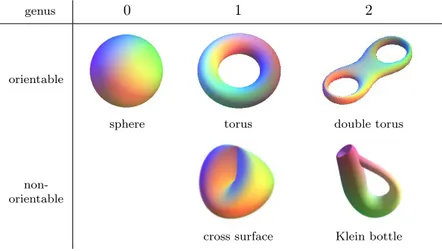
2.4.1 Shape topology . . . 55
2.4.2 Pattern topology . . . 62
2.4.3 Pattern and shape topology . . . 65
2.4.4 Pattern topology and geometry . . . 68
2.5 Summary . . . 69
3 Thesis scope 71 3.1 Research objectives . . . 71
3.2 Design approach . . . 75
3.3 Intellectual contributions . . . 77
II
Geometry-coded topology finding
81
4 Feature-based exploration 83 4.1 Motivations . . . 83 4.2 Surface decomposition . . . 84 4.2.1 Surface skeletonisation . . . 85 4.2.2 Skeleton decomposition . . . 87 4.2.3 Decomposition modification . . . 88 4.2.4 Examples . . . 90 4.2.5 Non-null-genus shapes . . . 90 4.2.6 Computation time . . . 93 4.3 Additional features . . . 94 4.3.1 Point features . . . 94 4.3.2 Curve features . . . 984.4 Feature-based topology finding . . . 101
4.4.1 Design problem . . . 101
4.4.2 Pattern design . . . 103
4.4.3 Numerical results . . . 105
III
Graph-coded topology finding
109
5 Rule-based exploration 111
5.1 Motivations . . . 111
5.2 Quad mesh structure . . . 113
5.2.1 Quad mesh strips . . . 113
5.2.2 Counting strips . . . 115
5.2.3 Strip graph . . . 117
5.3 Quad-mesh grammar . . . 119
5.3.1 Strip addition . . . 120
5.3.2 Strip deletion . . . 123
5.3.3 Strip data update . . . 125
5.3.4 Strip graph relation . . . 126
5.3.5 High-genus example . . . 126
5.4 Rule-based topology finding . . . 129
5.4.1 Design problem . . . 129 5.4.2 Pattern design . . . 130 5.4.3 Numerical results . . . 131 5.5 Summary of contributions . . . 136 6 Similarity-informed exploration 139 6.1 Motivations . . . 139 6.2 Quad-mesh equality . . . 140 6.2.1 Graph isomorphism . . . 140 6.2.2 Mesh isomorphism . . . 142 6.2.3 Quad-mesh isomorphism . . . 142 6.2.4 Pseudo-quad-mesh isomorphism . . . 144 6.3 Quad-mesh similarity . . . 144 6.3.1 Definition . . . 145 6.3.2 Computation . . . 147 6.3.3 Validation . . . 152 6.3.4 Limitation . . . 152 6.4 Quad-mesh combination . . . 155 6.4.1 Approach . . . 155
6.4.2 Hybrid mesh generation . . . 157
6.4.3 Data management . . . 159
6.4.4 Result prediction . . . 162
6.5 Similarity-informed topology finding . . . 163
6.5.1 Similarity from one design . . . 163
6.6 Summary of contributions . . . 180 7 Two-colouring exploration 183 7.1 Motivations . . . 183 7.2 Two-colouring characterisation . . . 187 7.2.1 Types of two-colouring . . . 187 7.2.2 Two-colouring requirements . . . 189 7.2.3 Index-based characterisation . . . 193 7.2.4 Graph-based characterisation . . . 194 7.3 Two-colouring search . . . 197 7.3.1 Third-colour deletion . . . 198 7.3.2 Two-colour projection . . . 199 7.3.3 Search algorithm . . . 203 7.3.4 Examples . . . 207
7.4 Two-coloured topology finding . . . 214
7.4.1 Design problem . . . 216
7.4.2 Pattern design . . . 216
7.4.3 Numerical results . . . 221
7.5 Summary of contributions . . . 226
7.6 Appendix . . . 229
7.6.1 Algorithm validation results . . . 229
7.6.2 Structural application results . . . 229
IV
String-coded topology finding
233
8 Alphabet-based exploration 235 8.1 Motivations . . . 235 8.2 String encoding . . . 237 8.2.1 Background . . . 237 8.2.2 Movement operations . . . 239 8.2.3 Editing operations . . . 241 8.2.4 Operation alphabet . . . 245 8.2.5 Examples . . . 2458.2.6 Lack of string-to-mesh isomorphism . . . 247
8.3 String modification . . . 247
8.3.1 Definition . . . 248
8.3.2 Combination . . . 250
8.4 String distance . . . 251
8.4.2 Examples . . . 252
8.5 Towards evolution-driven topology finding . . . 255
8.6 Summary of contributions . . . 257
V
Implementation
259
9 compas_singular 261 9.1 Source . . . 262 9.1.1 Data structures . . . 262 9.1.2 Algorithms . . . 264 9.1.3 Speed . . . 264 9.2 Applications . . . 264VI
Conclusion
267
10 Conclusion 269 10.1 Contributions . . . 269 10.2 Perspectives . . . 27010.2.1 Richer architectural applications . . . 270
10.2.2 Novel approach to topology optimisation . . . 271
10.2.3 Mapping and clustering for aided exploration . . . 271
10.2.4 Data-driven exploration . . . 271
10.2.5 From the discrete to the continuum . . . 272
10.2.6 Advanced construction systems . . . 272
10.2.7 Triangle-based patterns . . . 273
10.2.8 Spatial patterns . . . 273
10.2.9 Patterns in additive manufacturing . . . 274
10.2.10 Meshing applications in other fields . . . 274
Part I
Chapter 1
Context
’What matters is pattern and its connectivity.’ Cecil Balmond in Informal ’Topology is the science of fundamental pattern and structural relationships of event constellations.’ Richard Buckminster Fuller in Operating Manual for Spaceship Earth Architecture, structure, connectivity, topology and pattern are synonyms to describe the arrangement between elements. Patterns are ubiquitous in design, including architectural, structural design and appear in the design of different structural systems. For shell-like structures such as shells, vaults or gridshells, represented as a surface or a mesh, the pattern can represent the arrangement between beams, blocks or forces.
This chapter presents the context for structural design of patterns. Sec-tion 1.1 presents computational structural design. Section 1.2 highlights how patterns come into play in structural design. Section 1.3 lists the dif-ferent design aspects of patterns. Section1.4sets the focus of this thesis on the structural design of quad meshes and their singularities.
1.1
Computational structural design
Structural design lies at the interface of architecture and engineering, be-tween architectural design and structural analysis. Designing a structure
re-quires theoretical knowledge on geometry and mechanics, applied knowledge on fabrication technologies and construction codes, and a sense of aesthetics. Structures as a whole are not mass-produced, contrary to the automotive industry, for instance. A structure stems from a design process with spe-cific design intents, engineering requirements and construction constraints. This rich and intense process is highly non-linear to achieve a design that meets all objectives and constraints. Hand drawing and physical modelling are insightful processes for the design of structures but were replaced by digital modelling to efficiently perform an iterative search. Computer-aided design empowers designers to improve the design process, save time, energy and money, or even make a project feasible. Indeed, computer-aided design allows rapidly exploring and evaluating a large number of designs to search for the most suitable ones, before physical prototyping and testing.
1.1.1
Design exploration
Computational models represent the geometry and the connectivity of the structure, on which the designer can run mechanical and other analyses. To benefit from such models beyond numerical analysis, building parametric models enables efficient and interactive design exploration via the modifica-tion of the parameters that describe the model.
1.1.1.1 Parametric design
Setting a parametric model allows interactive design through the modifi-cation of values. Grasshopper3D for Rhino3D or Dynamo Studio by Au-todesk provide such parametric environments, for instance. Regarding a truss, whose pattern is the beam layout, two simple parameters can be the span and the height, as in Figure1.1a. Thereby, the designer can explore the geometry and the density of the truss. The models are re-generated when changing these values instead of re-drawing the model. The parameters de-fine the flexibility of the model and therefore, the boundaries of the design space. A flexible parametric model of a truss can consider each coordinate of each node as a parameter to allow free-form shapes and not only rectangular ones, as in Figure1.1b. However, the higher the number of parameters, the higher the dimension of the corresponding design space. And therefore, the more complex the exploration for the search for an optimal design. How much does adding a specific parameter enrich the design space? The defi-nition of a parametric model is a trade-off between richness and complexity and must be carefully determined.
Parametric design enables geometric exploration but not a full explo-ration of a computational model. The geometry-related parameters are de-pendent on the connectivity of the structure that defines the organisation between its elements. An extended approach is required to embrace full exploration, which includes connectivity design of structures.
(a) Limited parametric
design (b) Flexible parametricdesign (c) Trans-parametricdesign
Figure 1.1 – Parametric and trans-parametric design spaces for a truss.
1.1.1.2 Trans-parametric design
Beyond parametric design, trans-parametric design uses discrete parameters, as opposed to continuous-valued parameters. Trans-parametric explores the connectivity of a design and traverses different parametric spaces, also called meta-parametric design by Harding [Harding et al., 2012,Harding and Shep-herd, 2017]. These discrete parameters can define the layout of the beams of a truss, as in Figure1.1cwith different bracing configurations. The com-binatorial nature of these parameters does not allow to directly enumerate them to define the dimension of the design space. Parametric design ex-plores geometrical design spaces. On the contrary, trans-parametric design tackles topological design spaces, encapsulating multiple geometrical spaces. The parameters that perform the topological modifications must be carefully determined as well, as it defines the topological space to explore.
Density parameters, which can control the number of bracing elements in a truss, for instance, change the connectivity quantitatively but not qual-itatively. The exploration of the density parameters is not combinatorial.
Although density parameters are not continuous but discrete, the finite set of density parameters enrich the parametric model.
The design space derives from the selected continuous parameters and discrete parameters. The higher the number of these, the larger the design space. However, exploring larger design spaces is more complex without ensuring to find more suitable designs. Interactive methods must support and guide the designer.
1.1.2
Design interactivity
Defining parametric and trans-parametric models can result in the compu-tation of rich design spaces that exceed in size what a designer can com-prehend. Nevertheless, the interaction between the human and the machine using specific search algorithms allows the designer to appreciate the design space and find the most relevant designs. These designs should respect the project constraints and optimise the design metrics.
1.1.2.1 Constrained design
Not all and not even most designs in the design space are relevant. Instead of finding optimal designs in the general design space, constraining exploration to the relevant design subspaces allows finding their optimal designs more efficiently. Figure1.2aillustrates this opposition between the general design space in white and the specific subspace in red.
A first example is constraining exploration to compression-only networks in equilibrium with a given load case [Block and Ochsendorf, 2007] and then finding the one with the minimum load path that relates to the structure of minimum volume [Liew et al., 2019].
A second example is constraining exploration to structures with planar faces for flat panel fabrication [Mesnil et al., 2017e] and then performing structural optimisation [Mesnil et al., 2018b].
This constrained exploration approach drives the designer towards sub-spaces that contain the most relevant designs. These constraints can be of architectural, structural or constructive nature.
A structure often has to comply with multiple constraints. Constrained-exploration strategies can be combined to search for a potential intersection between the different subspaces to respect these multiple constraints. In Fig-ure1.2b, the intersection in red of the two subspaces further reduces the size of the space to explore. However, this intersection between subspaces may not exist. Nevertheless, a hierarchy usually exists between constraints. For a
steel and glass gridshell, a designer may favour affordable planar panels over compression-only equilibrium, although wishing to be close to such an equi-librium. For a stone vault, a design may on the contrary favour compression-only equilibrium over voussoir planarity, although wishing to have almost planar faces. Based on the constraint hierarchy, exploration can be con-strained to the designs in the primary subspaces. Among these designs, exploration should favour the ones close to the secondary subspaces. In Fig-ure1.2c, not all designs of the primary subspace have the same relevance — the closer to the secondary subspace, the more relevant, as visualised with a white-to-red gradient. GENERAL SPACE SUBSPACE TARGET DESIGNS (a) Unique subspace GENERAL SPACE SUBSPACE INTERSECTION TARGET DESIGNS (b) Intersecting subspaces PRIMARY
SUBSPACE SECONDARYSUBSPACE
GENERAL SPACE
TARGET DESIGNS
(c) Disjoint subspaces
Figure 1.2 – Constraining exploration of the general design space based on one or several subspaces that correspond to primary or secondary constraints to meet. The most relevant design space areas are highlighted in red.
1.1.2.2 Informed design
Even constrained to a subspace, finding an optimal or heuristic design is challenging. Performance can be assessed during the search through the design space using mechanical and environmental analysis, for instance. Searching for efficient designs can be performed in an enumerative manner. Alternatively, the performance of tested designs can inform the generation of more efficient ones, following the judgement of the designer or using op-timisation algorithms.
These computational approaches can apply to the design of patterns, which find many applications in the realm of structural design, including the design of shell-like structures.
1.2
Patterns in structural design
A pattern can represent different structural elements, like beams, walls or slabs. The focus of this thesis lies on the design of large-span discrete or continuous shell-like structures – or surface structures – like shells, vaults or gridshells. Shell-like structures can span large areas thanks to their double curvature, which provides geometrical stiffness. For their design, these large-scale structures become discrete patterns of smaller elements. The nature of these patterns can be of different types with different purposes.
1.2.1
Materialising elements
Patterns can be used to materialise the elements of the load-bearing and cladding system to fabricate and assemble. The elements of the pattern can represent nodes, beams or ribs, panels or voussoirs. Figure1.3features some of these patterns: a set of GFRP composite beams to form an elastic gridshell from a flat grid layout (Figure 1.3a); a tessellation of limestone voussoirs to form a compression-only stone vault (Figure1.3b); a steel cable net to serve as flexible formwork for a concrete shell (Figure 1.3c); an as-sembly of timber beams to form a nexorade-like gridshell braced with panels (Figure 1.3d). The design of these material patterns relates to structural performance, fabrication, assembly and construction requirements, which relate to ecological and economic costs. The material pattern can represent the structure or the envelope alone if the two are decoupled [Mesnil, 2018].
1.2.2
Modelling equilibria
Patterns can be used to model the equilibrium between a set of forces in the structure, such as thrust networks [Block and Ochsendorf, 2007], load paths [Liew et al., 2018] or struts-and-ties [Schlaich and Schafer, 1991]. These force patterns can be used to find structures in pure compression or pure tension, for instance. They can also be used to confirm or infirm the structural safety of a design following simplified hypotheses, thanks to the lower-bound theorem in yield design [Heyman, 1997, Schlaich and Schafer, 1991]. A force pattern can become a material pattern like cable-net elements, which directly carry the forces. Alternatively, the force pattern can inform the design of a material pattern like masonry-vault voussoirs, whose normals should be as orthogonal as possible to the compressive forces to prevent sliding failure vaults [Rippmann and Block, 2018].
(a) Beam grid of the Ephemeral Cathe-dral in Créteil, France
[Du Peloux et al., 2015] (Photo credits: thinkshell.fr)
(b) Voussoir tessellation of the Ar-madillo Vault in Venice, Italy
[Rippmann et al., 2016] (Photo credits: Iwan Baan)
(c) Cable layout of the prototype for the NEST HiLo roof in Dübendorf, Switzerland
[Méndez Echenagucia et al., 2018] (Photo credits: Naida Iljazovic)
(d) Beam network of a shell-nexorade hybrid at École des Ponts, Champs-sur-Marne, France
[Mesnil et al., 2018a]
(Photo credits: Romain Mesnil)
Figure 1.3 – Examples of material patterns of shell-like systems like gridhsells, vaults, nets and nexorades.
1.2.3
Parameterising surfaces
Patterns can apply to the parameterisation of surfaces. The pattern forms a digital discretisation of a continuous shell. They do not represent element or force distributions but provide a map of the surface. Parameterisation patterns can be used as control mesh for surfaces of NURBS or BREP [Pottmann et al., 2007a] to construct an underlying smooth surface. Pa-rameterisation patterns can apply to form finding [Mesnil et al., 2018b], iso-geometric analysis [Längst et al., 2017], continuous topology optimisation [Bendsøe and Sigmund, 2013] or finite element analysis. Moreover, folds [Mesnil et al., 2017a], corrugations [Norman et al., 2009] or perforations
[Schlaich, 2018] can be integrated. These parameterisation patterns allow storing any discrete data on the surface, like vector fields or cross fields, a natural manner of storing information in digital processing.
Patterns in structural design can be differentiated whether they relate to material, equilibrium or data. Nevertheless, the same aspects must be taken into account when designing these patterns.
1.3
Design aspects of patterns
The two main design aspects of a pattern are its geometry and its topology.
1.3.1
Geometrical aspects
The geometry of a pattern consists of the position of its vertices, the three coordinates x, y and z in the 3D space. A pattern with n vertices has thus 3ngeometrical degrees of freedom. These degrees of freedom are continuous parameters enabling the use of continuous algorithms for design and optimi-sation [Hojjat et al., 2014]. Grouping these parameters can bring coherence and constraints while reducing the size of the design space to search. Ei-ther implicitly using data analysis or explicitly using geometrical objects like curves or surfaces on which to constrain the vertices. Geometrical design methods aim at computing these parameters to fulfil specific goals. Such approaches usually assume a fixed topology.
1.3.2
Topological aspects
In this thesis, the topology of a pattern refers to the connectivity between its vertices. The topology is a rich combinatorial problem controlled by a flexible number of discrete parameters. On the contrary, geometrical pa-rameters consist of a fixed number of continuous papa-rameters. The topology is embedded in the geometry. Indeed, two patterns with the same geometry entail that they have the same topology. However, two patterns with the same topology do not necessarily have the same geometry. Two patterns have the same topology if they can have the same geometry using a con-tinuous, reversible geometrical transformation, known as homotopy. Such a transformation does not tear the shape or break the pattern. A square and a rectangle do not have the same geometry but have the same topology, whereas a disc and a sphere do not have the same geometry nor the same topology.
The design of the topology of a pattern can be decomposed into sub-problems to understand its regularity and irregularity.
(a) The frame network of the stadium and the Voronoi grid of the pool of the 2008 Beijing Olympic Games
(Source: structurae.info)
(b) Polytope pattern of the courtyard roof of the Dutch Maritime Museum in Amsterdam, The Netherlands
(Source: wbarchitectures.be)
(c) Timber gridshell with a semi-reg-ular, Kagome pattern of the Centre Pompidou in Metz, France
(Source: damienguillou.fr)
(d) Triangulated pattern of the geodesic dome of the Zeiss-Planetar-ium in Jena, Germany
(Source: zendome.de)
Figure 1.4 – Non-structured patterns, non-regular patterns and regular pat-terns with some irregularities in structural design.
1.3.2.1 Tessellations
The field of tessellations is a rich world that describes the fundamental mod-ule in a pattern [Grünbaum and Shephard, 1987]. Tessellations have logic, and therefore, are structured, characterised with high regularity. Tessella-tions are opposed to unstructured patterns where the types of and adjacency between elements are irregular. The applications of unstructured patterns
in structural design are rare. Figure 1.4 presents some examples with the Voronoi pattern and the network of curved beams of the Olympic swimming pool and stadium in Beijing, China, in Figure1.4a, the Dutch Maritime Mu-seum in Amsterdam, The Netherlands, in Figure1.4b.
The logic of the tessellation of a pattern describes its repeated module. Regular tessellations are the ones where each polygon is identical. There are only three for the plane: tessellations of regular quads, triangles and hexagons, as shown in Figure1.5. In each of these tessellations, faces have the same number of vertices, edges have the same length and vertices have the same number of neighbours.
Figure 1.5 – The three regular tessellations of the plane.
Figure 1.6 – The eight semi-regular tessellations of the plane. The colours represent the polygons with the same number of edges.
Semi-regular tessellations resort to two or more regular polygons. There are eight semi-regular tessellations for the plane, combining quads, triangles and hexagons, as well as octagons and dodecagons, as shown in Figure1.6. Each vertex is adjacent to the same sequence of polygons. The regular and
semi-regular tessellations are different for the 3D space or non-Euclidean spaces like the sphere. The polygons of these tessellations are distorted on curved surfaces, with edges of different lengths. Mapping from the plane to the surface entails a loss in geometrical regularity. Nevertheless, they have the same topological regularity. The timber gridshell of the Centre Pompi-dou in Metz, France, shown in Figure 1.4cor the Yas Mall in Abu Dhabi, the United Arab Emirates, are based on such semi-regular tessellations con-sisting of hexagons and triangles, and quads and triangles, respectively.
The geodesic dome in Jena, Germany in Figure1.4d is a particular ex-ample. The faces of the beam pattern are triangles with the same geometry. They can map the curved surface of a sphere thanks to a few irregular nodes that are adjacent to five faces instead of six, locally breaking the regular-ity of the tessellation. This specific organisation stem from a discretised icosahedron mapped to the sphere.
In construction, regularity in both geometry and topology matters [ Mes-nil et al., 2017b]. Different patterns can provide different properties. For instance, Kagome patterns have the same node complexity with shorter beams compared to quad meshes, offering interesting properties regarding fabrication and buckling [Mesnil et al., 2017b]. Nevertheless, the lack of modelling and design approach that tackles a large variety of tessellations is an obstacle for their exploration and implementation in structural de-sign. The application of non-fully regular patterns in structural design as in Figures 1.4b and 1.4care rare and regular patterns are preferred as in Figure 1.4d. The lack of a general topological design approach with tools that encapsulate the larger family of tessellations and structured patterns can explain their rarity. Nevertheless, some work in this direction resort to tessellation operators for the design of space frames [Koronaki et al., 2017]. 1.3.2.2 Density
The density of a pattern relates to the global number of elements. For a regular quad tessellation, the number of elements in each of the two grid directions characterises the density. The density parameters is a finite set of discrete values to explore when designing a pattern, as opposed to geometry-related continuous parameters.
1.3.2.3 Singularities
Patterns and tessellations are synonyms of regularity. However, singular vertex or face elements can be included, locally breaking the pattern
reg-(a) Waffle slab without singularities
(source: HOLEDECK) (b) Ribbed slab with singularities(source: Pier Luigi Nervi)
Figure 1.7 – Slab systems with different geometrical and topological regu-larities due to singuregu-larities in the patterns.
ularity. The tessellation of the geodesic dome in Figure 1.4d consists of regular triangles with regular nodes connecting six beams, except for some irregular nodes connecting five beams. These singular nodes are necessary to map the sphere.
In a quad pattern, regular faces and vertices have four edges, whereas irregular or singular vertices have a valency – a number of edges – differ-ent from four. These local irregularities have a global influence as the flow and the relation between elements are modified. In structural design, it re-lates to modifying the layout of structural and cladding elements in material patterns, the force layout in force patterns or the edge layout in parame-terisation patterns. Figure 1.7 opposes two slab systems. The waffle slab in Figure1.7ais highly regular to ease fabrication and assembly. Although, this pattern does not take the static system into account and reinforcement is necessary to avoid the columns to punch through due to shear forces. The ribbed slab of Pier Luigi Nervi in Figure1.7b includes singularities to follow statics considerations and steer the beams towards the columns. This structural efficiency comes at a cost on pattern complexity, regarding topol-ogy and geometry, which impacts the fabrication process. Developments in digital fabrication with technologies like 3D printing provide new flex-ibility in the fabrication of complex structures. These technologies apply to a varied range of scales and set of materials, like the sand 3D-printed floor prototype of the Block Research Group [Rippmann et al., 2018]. The general work towards mass-customisation ease the integration of singular elements in the fabrication process. The design of the geometry and the topology is a dialogue with the many project-specific design aspects. These
influential aspects include aesthetics, statics, fabrication, assembly, as well as sustainability and cost.
Changing singularities in a quad mesh induces a different flow and re-lation between elements, as shown in Figure 1.8. In this thesis, the sin-gularities in quad meshes are highlighted in pink, and the successive edges stemming from them are highlighted in black. The singularities in the quad meshes are vertices with an irregular valency, meaning different from four edges off the boundary and three on the boundary. From the quad mesh with four singularities in Figure1.8ato the mesh with two additional ones in Figure1.8b, the quantitative number of elements and their qualitative rela-tion differ. The independent density parameters A to F along the boundary indicate these differences.
Takayama et al. [Takayama et al., 2014] present a set of quad-mesh patterns with different singularities for N-sided patches with a prescribed number of subdivisions on each side. Matching the prescribed number of subdivisions and the length of the sides allows to obtain quad meshes with a regular distribution of the boundary edges thanks to the singularities as in Figure1.8.
B
A A
B
(a) Two density parame-ters B A C C E E B A D F F D
(b) Six density parameters
Figure 1.8 – Different singularities in a quad mesh induce qualitatively dif-ferent relations between its elements. The singularities are highlighted in pink and the successive edges stemming from them are highlighted in black. These topological singularities occur also in the meshes used for Finite Element Analysis. However, they are different from the field singularities, which occur in the stress field, for instance, where the values do not converge and therefore the field is not defined.
in structural design of shell-like structures thanks to their flexibility to map surfaces and represent different structural systems. Moreover, their singu-larities appear as a particularly influential design aspect.
1.4
Structural design of quad-mesh patterns
Quad-mesh patterns find a large set of applications in structural design of shell-like structures. Mechanical, fabrication and construction aspects must inform the design of their geometry and topology.
1.4.1
Quad-mesh patterns
Surfaces can be discretised using any pattern. However, surfaces are two-dimensional objects, naturally described with two parameters. Therefore, quad meshes and their bidirectional nature correspond to this natural de-scription of surfaces.
Moreover, integration of cross fields on a shell yield quad meshes with correspondence of the two parameterisation directions. Principal curvature directions and principal stress directions are such cross fields, which archi-tects and engineers are familiar with and use to interpret to understand their design. For instance, Nervi’s floors [Nervi, 1965] are elegant and efficient ex-amples of interpretation of principal stress directions to form a ribbed slab, as shown in Figure 1.7.
Furthermore, quad meshes can serve as an underlying representation of many structural systems. The structure stems either directly or indirectly from the quad-mesh elements, as illustrated in Figure 1.9 with continuous beams, corrugation patterns and staggered bricks.
Quad-mesh patterns offer other design options with different pros and cons to triangular-mesh patterns. As expressed by Schlaich and Schober [Schlaich and Schober, 2005,Schober, 2015], quad meshes for steel and glass gridshells are more transparent and have simpler nodes than a triangulated mesh. However, quad-mesh structures rely on member and node bending stiffness, especially against in-plane shear, whereas triangular-mesh struc-tures rely on member axial stiffness, thanks to the stability of triangles. Moreover, a triangle is by definition planar, on the contrary to a quad, which can be curved. Stiff nodes or braced panels compensate for the lack of structural stability. Pre-or post-rationalisation strategies tackle the prob-lem of panel curvature [Schober, 2015,Mesnil et al., 2017a,Liu et al., 2006].
(a) Axis of beams (b) Map of corrugations (c) Frame of bricks
Figure 1.9 – Quad meshes in dashed red and blue lines representing different structural systems in black and grey.
1.4.2
Geometrical design
Geometrical exploration aims at designing efficient and feasible structures by modifying the position of the mesh vertices to meet some requirements and optimise objectives. Form-finding methods can be force-based to guarantee membrane equilibrium, like Force Density Method [Schek, 1974], Dynamic Relaxation [Barnes, 1999], Thrust Network Analysis [Block and Ochsendorf, 2007] or Update Reference Strategy [Bletzinger and Ramm, 1999], or technology-based to ease fabrication and construction, like Scale-Trans Surfaces [Glymph et al., 2004] or Marionette Meshes [Mesnil et al., 2017e]. These strategies constrain design exploration to the relevant subspaces. These methods can be combined with optimisation strategies to further search these subspaces [Bletzinger and Ramm, 1993,Mesnil et al., 2018b]. Optimisation algorithms for architectural geometry allow rationalising forms based on multiple ob-jectives, like ShapeOp [Deuss et al., 2015], based on projective dynamics [Bouaziz et al., 2014]. Nevertheless, the earlier the integration of design constraints, the easier the design process, which motivates the use of pre-rationalisation versus post-pre-rationalisation [Mesnil et al., 2017a].
Yet, topology matters for exploration. Indeed, the topology of the pat-tern sets the bounds of the available geometrical design space within the more general design space. This available geometrical design space repre-sents all the possible geometries for a given topology.
Figure 1.10 – The central singularity of the concrete shell of the CNIT in La Défense, France make the design feasible by orientating the stiffening corrugation pattern towards the supports (source: defense-92.fr).
1.4.3
Topological design
Exploring different configurations of singularities modifies the flow of edges. These edges can represent the orientation of elements, the flows of forces or the directions of parameterisations. The definition of the geometry and the density depend on the singularities. As the most upstream design aspect, singularities define all the other downstream degrees of freedom and are therefore the most influential one. A poor topology will not yield efficient or even feasible geometrical designs. For instance, the CNIT shown in Figure 1.10 and designed by Nicolas Esquillan is a concrete shell that spans the concrete-shell world record of 218 meters thanks to stiffening corrugations [Motro and Maurin, 2011]. The central singularity directs the pattern be-tween the supports. Thereof, the corrugations stiffen the shell in the proper direction, making such an achievement possible.
Many design objectives relate to geometry, like panel planarity or compression-only equilibrium. However, some topological properties, like maximum node valency, play an important role in structural design, independently from ge-ometry. For instance, the CNIT can not be corrugated in both directions; otherwise, a resulting eggbox pattern would weaken both directions instead of reinforcing one. The condition for non-self-crossing corrugations depends on the singularities in the quad mesh and is not systematically guaranteed. Figure1.11opposes the pattern of the CNIT in Figure1.11ato another one that is not efficient nor feasible in Figure 1.11b. The pattern topology in Figure 1.11b does not allow to orientate the elements directly to the support. Moreover, it creates three groups of non-overlapping elements due to the central three-valent singularity. One group can not be chosen to form stiffening corrugations all over the surface. On the contrary, the pattern topology in Figure1.11aintegrates these requirements.
This example illustrates that the pattern, its topology and the related geometrical space may not contain efficient or even feasible designs if poorly designed.
(a) Efficient and feasible pattern
topology (b) Inefficient and unfeasible patterntopology
Figure 1.11 – Two different quad-mesh pattern topologies for a structure sup-ported on three corners only, represent by black arrows. Efficiency comes from directing the continuous coloured elements towards the supports. Fea-sibility comes from the existence of one coloured group of non-overlapping continuous elements to introduce stiffening corrugations all over the surface.
1.5
Summary
Quad meshes can be used to model different objects for the design of struc-tures. Significant work in architectural geometry, form finding and shape optimisation enable geometrical design of these patterns. Unfortunately, similar approaches are missing regarding the topology of these patterns, which has a strong influence on all design aspects. Exploring the topol-ogy of quad-mesh patterns necessitate a trans-parametric design approach, beyond parametric design. Among the different topological aspects, the singularities in the pattern have the most influence.
The next chapter presents the current strategies related to topological designs of patterns in general, with their benefits and their limitations, and complementary background on the topology of shapes and meshes.
Chapter 2
Literature review
The design of singularities in quad meshes is a critical aspect in structural design of patterns for shell-like structures. Additional background to archi-tectural geometry and form finding is necessary to grasp the specific chal-lenges of topological design of such objects.
Section 2.1 clarifies the pros and cons of current structural design ap-proaches for the topology of quad meshes. Section2.2shows how rule-based design can be applied to topological trans-parametric design. Section 2.3 introduces the field of topology with graph theory. Section2.4presents the specific concepts and properties of quad meshes.
2.1
Design of patterns for structures
The current structural design approaches for the topology of quad-mesh patterns, both in practice and research, present several interests but different levels of limitations as well. The main approaches are presented, starting from the most simple ones.
2.1.1
Trimming grids
A first approach is to design a regular quad-mesh grid on a large initial surface. Then, trimming along the boundary of the shell fits the pattern to a landscape or existing buildings, for instance. No singularities occur off the boundary of the shell, but the boundary includes a series of irregular vertex and face elements due to the trimming.
(a) The trimmed quad-mesh pattern of the Cabot Circus Shopping Centre roof
in Bristol, England [Schober and
Jus-tiz, 2012]
(b) The sculpted triangulated quad-mesh pattern of the New Trade Fair in
Milan, Italy [Schlaich et al., 2005]
(c) The statics-integrated quad-mesh pattern of the zoology lecture hall at the University of Freiburg, Germany [Antony et al., 2014]
(d) The topology-optimised quad-mesh pattern of the building bridge for the
Zendai competition, China [Beghini
et al., 2014]
Figure 2.1 – Projects with quad-mesh patterns following different structural design strategies.
The roof of the shopping centre of the Cabot Circus in Bristol, Eng-land, shown in Figure2.1a, is a gridshell with a quad-mesh pattern of steel beams and glass panels. The design follows the geometry of a trans-scale surface to guarantee planar quad panels [Schober and Justiz, 2012]. The boundary of the surface is trimmed to follow the edge of the adjacent build-ings. The pattern does not reflect the boundary and support conditions. Trimming induces irregular elements to fabricate and assemble, such as tri-angular or pentagonal faces or very short edges along the boundary. Trim-ming also interrupts the force flow carried by the beams, driving the loads
to the boundary to be carried by stiffer beams. Trimming is standard for such strategies where the designer does not entirely control the boundary [Schlaich and Schober, 1997,Schober, 2015]. These considerations are simi-lar when trimming the quad-mesh patterns for elastic gridshells generated on a target surface thanks to the compass method [Otto et al., 1974,Du Peloux et al., 2013]. The compass method yields a Chebychev net, a quad mesh with equal-length edges, which eases the planar layout operation before the erection process. However, the method initiates from an intersection point between two guide curves on the surface and does not take into account the boundaries.
A quad mesh requires singularities to fulfil boundary alignment without trimmed elements, which influences structural and construction aspects. An example of beneficial influence is yielding membrane equilibrium in funicular form finding through alignment to unsupported boundary [Panozzo et al., 2013].
2.1.2
Sculpting meshes
Designers can sculpt meshes manually or semi-automatically following some heuristic rules in a trial-and-error approach. Sculpting coarse meshes be-fore densification and application of different operators is an efficient design paradigm [Bhooshan et al., 2018]. Nevertheless, this approach relies on the experience and skill of the designer and still requires some manual labour that is not straightforward to transpose from one project to another.
The roof of the New Trade Fair in Milan, Italy, shown in Figure 2.1b is a steel and glass gridshell [Schlaich et al., 2005]. The structural pattern derives from a quad mesh with additional diagonals for triangulation of the quad faces in curved areas. Thanks to specific mesh modifications, the singularities provide a smooth transition from the top areas to the funnel areas. However, in the development of ad hoc modifications, the decisions are specific to the project context with limited application to other design problems.
2.1.3
Optimising layouts
Opposed to linear programming, which applies to continuous parameters, integer programming enables discrete optimisation [Schrijver, 1998]. The connectivity within a set of fixed vertices like the bar layout of a truss can be optimised using such solvers with heuristic methods like genetic al-gorithms. The problem is classically parameterised with point indices to
define the extremities of the bars [Suzuki and Knippers, 2017] or edge in-dices to the define the bar in a ground structure [He and Gilbert, 2016]. Shea and Cagan apply simulated annealing on shape grammars – or shape annealing – for optimisation of geodesic dome patterns [Shea and Cagan, 1997]. Bielefeldt et al. use genetic algorithms for topology optimisation of a bar layout [Bielefeldt et al., 2019a]. Including the position of the points in the optimisation process mixes discrete and continuous parameters, which can be tackled using mixed integer linear programming.
2.1.4
Integrating fields
Integration of cross fields for structural design allows generating informed patterns for different objectives. Integration of principal stress directions guarantees mechanical efficiency [Michell, 1904,Rozvany and Prager, 1976], while the integration of principal curvature directions ensures fabrication properties like panel planarity [Liu et al., 2006]. Heuristic rules can in-form the design of a custom field. The integration of such fields provides a pattern that respects these heuristic rules, like boundary and feature align-ment [Panozzo et al., 2013]. Quad-mesh generation following a cross-field is a complex problem. Although efficiently-formulated algorithms manage to yield high-quality meshes regarding geometrical quality and feature align-ment rapidly [Kälberer et al., 2007,Bommes et al., 2009,Jakob et al., 2015]. The cross-field defines the geometry and topology of the resulting quad mesh. More specifically, the singularities have the position and the connec-tivity of the ones of the cross-field. A singularity in a field is a point where the field is not defined. Therefore, depending on the numerical precision and the processing scheme, they can appear directly in the output mesh or indirectly as dual faces resulting from the integration of surrounding curves. Concrete plates and shells reinforced with ribs were made popular by the work of Pier Luigi Nervi [Nervi, 1965, Halpern et al., 2013]. The slab of the zoology lecture hall at the University of Freiburg, Germany, designed by Hans-Dieter Hecker [Hecker, 1969] and shown in Figure2.1cis stiffened by a pattern of concrete ribs derived from the integration of the principal bending directions. The ribs provide structural efficiency but necessitate custom formwork, which can be hard and expensive to implement. Never-theless, this system can compete with other ones, like hollow concrete slabs and prestressed concrete slabs, regarding sustainability assessment [Antony et al., 2014].
However, the design comes as a single result from the integration scheme. The topology of the quad mesh is not directly controlled, and post-processing
may be needed. Indeed, mild or substantial modifications of the topology in further design steps would allow integrating other requirements that the cross-field does not take into account.
The curvature analysis of the roof of the Visconti Courtyard for the department of Islamic Arts at the Louvre in Paris, France, yields a quad-dominant mesh [Zadravec et al., 2010,Wallner and Pottmann, 2011]. Even though all panels fulfil the planarity requirement for economical fabrication, the topology does not provide freedom for the optimisation procedure to fulfil the other requirements and constraints.
Schiftner and Balzer [Schiftner and Balzer, 2010] compare two designs for the steel and glass pattern on the geometry of the British Museum Great Court Roof, which was analytically defined by Williams [Williams, 2001]. The two quad-mesh patterns differ by their singularities, which stem from two different cross fields: the principal stress directions and the principal curvature directions. The former performs better regarding structural stiff-ness and the later regarding panel planarity, as shown in Figure 2.2. Both design aspects can be tackled simultaneously by form finding a shape that aligns the two cross fields [Kilian et al., 2017, Pellis and Pottmann, 2018]. However, this approach requires freedom in the design of the shape, and more project-specific design aspects must still come into play.
2.1.5
Concentrating distributions
Mechanical topology optimisation based on mechanical compliance yields both the geometry and the topology of the pattern as well [Bendsøe and Sigmund, 2013]. Continuous topology optimisation progressively removes the lower-stressed material in a continuous domain for given loading condi-tions, as for the bridge-building in Figure 2.1d. Discrete topology optimi-sation progressively removes the lower-stressed bars in a dense network for given loading conditions. Theoretically, the resulting ideal pattern should follow the principal stress lines and yield a quad-dominant mesh as in cross-field integration [Michell, 1904,Rozvany and Prager, 1976,He and Gilbert, 2016].
A topology-optimisation process returns highly optimised patterns re-garding mechanical considerations for a specific load condition. Neverthe-less, structures at the architecture scale must strike a compromise between the very varied combinations of load cases, such as dead loads, live loads, snow loads, wind loads, seismic loads. Moreover, these patterns are not necessarily feasible regarding construction considerations [Borgart, 2010]. In practice, the pattern is unstructured and does not even correspond to a
Figure 2.2 – Two pattern designs revisiting the British Museum roof. The topology at the top performs the best regarding the requirement on the right on minimising mechanical compliance. The topology at the bottom performs the best regarding the requirement on the left on minimising panel planarity [Schiftner and Balzer, 2010]. The singularities in a quad mesh, highlighted in pink, influence its efficiency and affordability, highlighting the importance of their design for the challenge of meeting trade-offs in multi-objective structural design.
mesh, which could be directly further processed.
However, optimisation approaches like field integration and topology op-timisation can be used as a starting design for further exploration, and as a collaboration means between architects and engineers for integrated design [Beghini et al., 2014]. Such initial results can inform the designer, who could be empowered by the possibility of editing these results and combining them for multi-objective design.
Complementary to these main strategies, a rule-based design approach can be considered for the topological design of patterns for structures for shell-like structures, as used in many applications.
2.2
Exploration of topological spaces
Topological spaces do not have the same structure as geometrical spaces. Geometrical spaces rely on continuous parameters. Rule-based design and grammars compensate for this lack of continuous parameters to perform topological exploration.
2.2.1
Non-parametric spaces
Spaces are differentiated whether they have a metric or not. 2.2.1.1 Parametric spaces
A set of independent continuous-valued parameters defines a parametric space. For instance, the set of the vertex coordinates describe the geometry of a mesh. Exploring these parameters within their defined ranges allows describing all the objects in the design space. Continuous optimisation al-gorithms can apply through the computation of these parameters.
For the fields of architectural and structural design, among others, Rhino’s Grasshopper, or Autodesk’s Dynamo, enable an active community of stu-dents, practitioners and researchers to perform parametric design. The pa-rameters can be interactively modified while visualising the resulting design. Mechanical, light, thermal or acoustic analysis, a variety of form-finding and shape-optimisation algorithms or BIM software can provide additional in-formation. Thanks to an open-source approach, hundreds of plugins with hundreds of thousands of downloads can be browsed through in food4Rhino, contributing to knowledge transfer [food4Rhino, 2019].
Parametric spaces are metric spaces because canonical metrics based on the n parameters x = [x0, ..., xn−1]T can be defined such as the L2distance
d: d(x, y) = v u u t n−1 X i=0 (xi− yi)2, (2.1)
which allows evaluating the distance – or similarity – between two ob-jects. In the 2D or 3D Euclidean space, three coordinates describe each point, and the L2 distance is the Euclidean distance, the length of the
straight line between the two points.
Metrics – or distances – must verify several properties: • the distance between any two objects is positive;
• if the distance between two objects x and y is zero, then x and y are identical, and reciprocally: d(x, y) = 0 ⇐⇒ x = y;
• the distance is symmetric: the distance from an object x to an object yis the same as the distance from y to x: d(x, y) = d(y, x);
• the distance, respects the triangle inequality: the distance between two objects x and z is equal or smaller than the one between x and any object y plus the one between y and z: d(x, z) ≤ d(x, y) + d(y, z). 2.2.1.2 Topological spaces
However, some design spaces do not have such parameters, like the beam layout of a truss. For such topology-related spaces, parametric exploration is not possible as a finite set of continuous parameters is missing. Indeed, a combinatorial nature characterises such spaces.
Moreover, the definition of a canonical metric, based on continuous pa-rameters, is not possible.
However, an alternative approach to parametric design enables topolog-ical exploration based on grammars of rules.
2.2.2
Rule-based design
Parametric design applies to continuous parameters. On the contrary, rule-based design applies topological modifications rule-based on a set of rules grouped in a grammar. Rule-based design goes beyond parametric design and into
the field of trans-parametric design [Harding et al., 2012,Harding and Shep-herd, 2017]. Thinking about topological design at an early stage of the design process unleashes new design possibilities in structural applications. For instance, Deleuran et al. [Deleuran et al., 2016] perform topological exploration of form-active hybrid structures using rules that modify the connectivity of a network of splines and cables.
2.2.3
Design grammars
Rule-based design encapsulates different approaches with design grammars that can apply to language, form and structure, through different levels of complexity, starting with formal grammars.
2.2.3.1 Formal grammars
Chomsky introduces in the 1950s generative design applied to language us-ing formal grammars [Chomsky, 1956,Chomsky, 1959]. A finite set of formal grammar rules apply modifications on a finite set of words, enabling the gen-eration of an infinite set of sentences. The design rules define the language – or design space – to which these sentences – or designs – belong.
L-systems extend formal grammars for the generation of geometries. 2.2.3.2 L-systems
Lindenmayer introduces in 1968 L-systems as a type of formal grammars to algorithmically describe the growth of plants, as shown in Figure 2.3 [Lindenmayer, 1968, Prusinkiewicz and Lindenmayer, 2012]. A set of rules applies to a string of characters that come from an alphabet. The inter-pretation of the string generates the corresponding shape, in the manner of turtle graphics [Goldman et al., 2004]. The rules are applied iteratively to generate different level of growth of the shape. The shape depends on the starting string axiom and the different parameters, in the case of para-metric rules. L-systems can also describe the generation of patterns such as fractals.
L-systems can apply to structural design as parameterisation strategies for the generation of designs. The combination of L-systems and genetic algorithms provides a means for topology optimisation for the search for statics-optimised designs [Kobayashi, 2010,Bielefeldt et al., 2019a].
Shape grammar do not modify a string but directly a geometry and found many applications for exploration and design of general geometries.
Figure 2.3 – L-systems are a specific type of formal grammars interpreted by turtle graphics designed for algorithmic generation of plants [Prusinkiewicz and Lindenmayer, 2012]. Here, the designs stem from a different number of iterations n, a different branching angle δ, a starting string axiom and one or several rule to iteratively apply.
2.2.3.3 Shape grammars
Stiny and Gips introduce in 1971 shape grammars for the generation of shapes in painting and sculpting [Stiny and Gips, 1971]. Subsequently, shape grammars found a large set of applications in many fields of design and engi-neering [Stiny, 2006, Knight and Stiny, 2015, Cagan, 2001]. A classification can be found in [Garcia, 2017].
Shape grammars at the architectural scale develop into architectural grammars.
Architectural grammars Architectural grammars include a variety of applications, such as Palladian villas [Stiny and Mitchell, 1978], Frank Lloyd Wright’s prairie houses [Koning and Eizenberg, 1981], Queen Anne Houses [Flemming, 1987], Yingazo Fashi Chinese buildings [Li et al., 2001] or Siza’s houses in Malagueira [Duarte, 2005]. The grammar decodes each architec-tural style, formalised and structured into a set of rules to generate multiple other designs that share the same characteristics. Design grammars also apply at other scales than the building. Urban shape grammars tackle the district, like the Medina of Marrakesh [Duarte et al., 2006], or the city, like Praia in Cabo Verde [Beirão et al., 2011]. Product shape grammars tackle specific styles of chairs [Knight, 1980], coffeemakers [Agarwal and Ca-gan, 1998] cars [McCormack et al., 2004] or tableware [e Costa and Duarte, 2013], for instance, allowing mass customisation. An architectural grammar
for housing rehabilitation takes into account the varied information like new usage, among others, instead of decoding a design style [Eloy and Duarte, 2011].
Even though architectural grammars focus on the arrangement of shapes, grammars can include functional aspects other than geometry.
Functional, structural and force grammars Shape grammars evolve into functional and structural grammars to include non-geometrical data re-lated to structures. This data can include structural-behaviour and construction-technology requirements. Engineering applications include houses [Mitchell, 1991], towers [Baldock et al., 2005, Baldock, 2007], halls [Geyer, 2008], bridges, [Mueller, 2014] or trusses [Shea et al., 1997]. Figure2.4 highlights an application to a shell-like system with a grammar applied to the design of geodesic domes [Shea and Cagan, 1997,Shea and Cagan, 1999]. Some ap-plications are specific to a fabrication technology, like CNC machines [Sass, 2006,Ertelt and Shea, 2009], instead of a structural system. Force grammars describe the organisation between forces, opposed to the one between spaces or elements, which can later materialise into a structure. Force grammars for graphic statics are introduced by Lee et al. applied to 2D edge networks [Lee et al., 2016b] and 3D cell decompositions [Lee et al., 2016a].
(a) Grammar (b) Examples (c) Designs
Figure 2.4 – Grammar for rule-based design of triangulated meshes for geodesic domes [Shea and Cagan, 1997].
The exploration of the topology of patterns and meshes resulted in the development of several operations, sometimes also framed as grammar rules, which are not specific to architecture and structures.
2.2.3.4 Mesh grammars
The large range of applications of meshes sparked the design of very different sets of rules tuned for specific objectives, mainly for aesthetics purpose. Ornamental design Hansmeyer and Dillenburger [Hansmeyer and
Dil-lenburger, 2013] introduce a mesh grammar following a formal grammar approach that modifies the density and the geometry of meshes to generate highly-detailed ornamental shapes. This grammar focuses on shape. Indeed the pattern and its singularities are not modified.
Visual optimisation In the field of computer graphics, quad-mesh gram-mars modify the topology to improve the regularity of dense and unstruc-tured meshes [Daniels et al., 2008, Daniels II et al., 2009, Tarini et al., 2010, Peng et al., 2011]. This regularity for modelling and representation concerns both geometry and topology. These quad-mesh grammars consist of a set of local rules that preserve the quad-mesh constraint, unlike other grammars for triangulated meshes for instance. Figure2.5 illustrates some of these rules [Tarini et al., 2010].
edge collapse diagonal collapse doublet removal edge rotate
vertex rotate
Figure 2.5 – A grammar rules for quad mesh visual-quality optimisation [Tarini et al., 2010].
Another family of quad-mesh grammars does not consist of rules but different patterns [Nasri et al., 2009, Takayama et al., 2014, Peng et al.,


![Figure 2.4 – Grammar for rule-based design of triangulated meshes for geodesic domes [ Shea and Cagan, 1997 ].](https://thumb-eu.123doks.com/thumbv2/123doknet/2581406.56640/50.701.93.557.503.787/figure-grammar-based-design-triangulated-meshes-geodesic-cagan.webp)