HAL Id: hal-01008383
https://hal.archives-ouvertes.fr/hal-01008383
Submitted on 6 May 2018
HAL is a multi-disciplinary open access
archive for the deposit and dissemination of sci-entific research documents, whether they are pub-lished or not. The documents may come from teaching and research institutions in France or abroad, or from public or private research centers.
L’archive ouverte pluridisciplinaire HAL, est destinée au dépôt et à la diffusion de documents scientifiques de niveau recherche, publiés ou non, émanant des établissements d’enseignement et de recherche français ou étrangers, des laboratoires publics ou privés.
Loading rate effects on foam cores for marine sandwich
structures
Eric Lolive, Pascal Casari, Peter Davies
To cite this version:
Eric Lolive, Pascal Casari, Peter Davies. Loading rate effects on foam cores for marine sandwich structures. Sandwich Structures 7: Advancing with Sandwich Structures and Materials, 2005, Aalborg, Denmark. �10.1007/1-4020-3848-8_90�. �hal-01008383�
LOADING RATE EFFECTS ON FOAM CORES
FOR MARINE SANDWICH STRUCTURES
Eric Lolive1, Pascal Casari2 and Peter Davies3 1
IUT Brest, LIME, Laboratoire d'Ingénierie Mécanique et Electrique, 29231 Brest, France 2
GeM, Institut de Recherche en Génie Civil et Mécanique 44322 Nantes, France 3
Materials and Structures group, Ifremer Brest Centre, 29280 Plouzané, France
Abstract This paper presents first results from a project which aims to generate foam core
properties under loading rates representative of those encountered during wave impact of racing y achts. First, special instrumentation enabled shear strain rates to be measured in-situ. Then a symmetrical shear test was designed to allow shear stress-strain behaviour to be determined at rates corresponding to those measured at sea. Image analysis was used to validate the test set-up. First results for high density foams indicate that quasi-static data may suffice for design.
Keywords: Foam core, PVC, high rate, shear, instrumentation.
1.
INTRODUCTION
Foam cores are widely used in the sandwich structures used for boat construction. These materials provide weight gains are often preferred to honeycomb cores in areas likely to encounter wave impacts. The selection of foam type and density is generally based on quasi-static design data but the loading rates can be very high in these regions. It is therefore of considerable interest to develop tests which enable properties to be determined at rates corresponding to service loading conditions. Several previous studies have addressed this subject and some data are available [1-4] but the development of new foam grades makes it difficult to compare these data.
The aim of the work described in this paper is threefold. First, measurements on a racing yacht using special shear strain plugs enabled strain rates to be measured. Then a test was designed to enable shear tests to be performed at these rates. Finally data was generated and the test procedure was validated using image analysis.
2.
SHEAR STRAIN MEASUREMENTS IN-SITU
Special instrumentation was designed and built in order to evaluate the strain rate levels encountered in a sandwich hull loaded under slamming conditions, Figure 1. A similar system has been used on pressure-loaded panels previously [5].
Strain gages are intrusive, and to assess this point, a calibration of strain levels has been performed in the laboratory using standard shear tests on the foam. A ratio of 2.37 was found between the mean strain level and that measured with the shear strain plug.
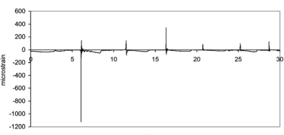
This ratio was used subsequently, when identical plugs were mounted on the racing yacht shown in Figure 1. Figure 2 shows an example of the data recorded.
Figure 2. Example of longitudinal shear strain measurements recorded at sea. Upper: 30
second recording, Lower: detail of 0.25 second recording.
Based on recordings such as these, core shear strain rates in the range 10-15%/second were measured. This does not mean that higher rates do not occur but it gives a first indication of the loading rate required for tests to compare different materials. This rate is not excessively high and can be
strain field can be generated. In this initial part of the project emphasis was placed on shear tests.
3.
SHEAR TEST
The shear properties of foams are usually determined by standard tests such as ASTM C273, NF T 54-605, Figure 3. The main disadvantage of these tests for high rate loading is the rotating links.
Figure 3. Standard shear test fixtures.
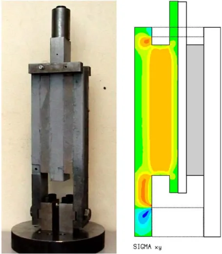
In order to minimize inertia effects during high rate loading a rigid symmetrical fixture was designed, Figure 4.
This configuration is easy to test but results in high stress gradients at points A and B. In order to limit these stress gradients, which increase as the specimen thickness increases, the fixture was modelled using SAMCEF© software. After a series of iterations the final test fixture is shown in Figure 5. The central support is made from aluminium alloy in order to reduce inertia, the outer supports are steel and are linked in order to make the structure rigid and avoid transverse movements. The specimen thickness is that of the panels used, width is 50mm and length is between 150 and 250 mm.
Figure 5. Test fixture and shear stress distribution.
specimens, which leads to failure initiation there. This results in an under-estimation of the non-linear behaviour, but has no influence on the elastic response.
4.
TEST PROCEDURE & MATERIALS
The fixture is mounted on a tensile test machine. The outer supports are fixed to the machine base. The central rail is displaced at a constant rate. An inductive transducer measures the relative movement of the inner and outer rails and a load cell measures the force.
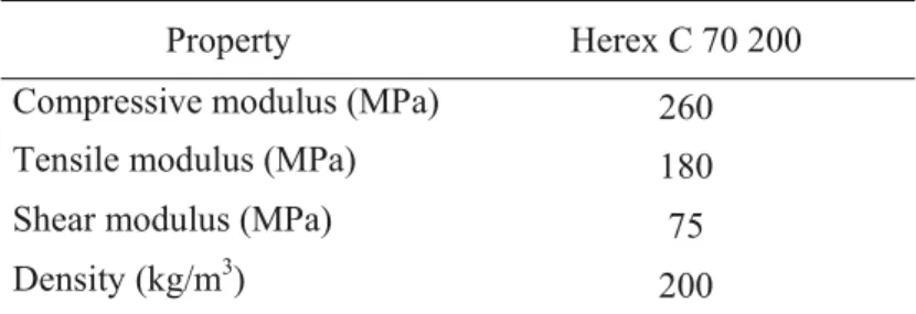
The foams tested were PVC foams supplied by Airex as 20mm thick panels. Results from tests on Herex C 70 200 foam will be presented here. The supplier’s data values, used in the FE analyses, are shown in Table 1.
Property Herex C 70 200 Compressive modulus (MPa) 260 Tensile modulus (MPa) 180 Shear modulus (MPa) 75 Density (kg/m3) 200 Table 1. Foam properties (supplier data).
First validation tests were performed at a loading rate of 1mm/min. The foam was bonded to the rails using a Redux 420 epoxy adhesive. These tests indicated a shear modulus of 85 MPa.
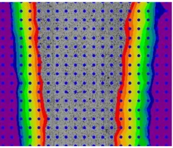
In order to remain within the load limits of the test machine (100 kN) the length of the specimen was reduced from 250 to 150mm. This results in a shorter uniform stress region and may invalidate the test, so an FE analysis was performed in order to establish the uniformity of local stresses in the region used for global modulus measurements, Figure 6. For the 150mm length specimen, the error in the shear modulus is estimated at 5%. It was therefore decided to used full strain field measurements, giving local strain measurements, to determine the shear response. Black paint spots sprayed onto a white background layer were used, with image analysis software. An example of the results from preliminary tests is shown in Figure 7. This showed clearly that with one of the early fixtures there was a tendency for the lower part of the fixture to close up during the test. The lower fixing
bolts were under-dimensioned, a subsequent fixture modification eliminated this e ffect.
Figure 6. Shear stress distributions, two specimen lengths.
Figure 7. Example of image of test with early fixture.
Following those initial static validation tests the influence of loading rate was examined. Some first results are shown below.
5.
RESULTS
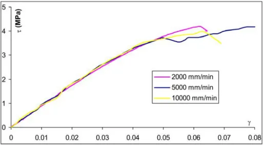
Tests were performed at three loading rates which are faster than the rates measured at sea. Figure 8 shows the global behaviour laws for the three rates. It is interesting to note that for this rigid 200 kg/m3 density material, no significant influence of loading rate is observed, at least up to 5% strain. This is in contrast to previous results reported for lighter foams. The shear moduli values measured are all in the range 85-90 MPa, compared to the value of 85 MPa measured in the test at 1 mm/minute.
Figure 8. Shear stress-shear strain curves for three loading rates.
6.
CONCLUSIONS
The aim of this project is to establish the appropriate foam properties to be used in the design of racing yachts and other vessels which are subjected to wave impact loads. Measurements at sea have identified the loading rates for one type of craft under certain sea conditions. A test fixture has been developed and validated using FE analysis and full strain field measurements in order to achieve these (and higher) loading rates. First tests results indicate that quasi-static data may suffice for high density rigid foams. Further work is underway to study lighter foams, other core materials and higher loading rates.
ACKNOWLEDGEMENT
The authors thank Rolland Jourdain, skipper of the 60’ IMOCA racing boat SILL for allowing the instrumentation and monitoring of the sandwich hull of the boat.
REFERENCES
1. Feichtinger, K.A., Test methods and performance of structural core materials-IIA Strain rate dependence of shear properties, 5th INERN Conf., October 1990.
2. Buene, L, Echtermeyer, A.T., Hayman, B., Sund, O.E. and Engh, B., Shear properties of GRP sandwich beams subjected to slamming loads, Proc. 2nd Sandwich Construction Conf., 1992.
3. Davies, P., Baizeau, R., Wahab, A., Pecault, S., Collombet, F. and Lataillade, J.L., Determination of material properties for structural sandwich calculations, from creep to impact loading, in Mechanics of Sandwich Structures, Vautrin (ed.), Kluwer, 1998, 327-336.
4. Van Gellhorn, E. and Reif, G., Think dynamic: dynamic test data for the design of dynamically loaded structures, Proc. 2ndd Sandwich Construction Conf., 1992.
5. Chakravarty, U., Mahfuz, H., Saha, M. and Jeelani, S., Strain rate effects on sandwich core materials: an experimental and analytical investigation, Acta Materiala 31, 2003, 1469-1479.
6. Hayman, B., Wiese, M., Davies, P., Choqueuse, D., Hoyning, B. and Mitusch, P., Foam cored sandwich panels under static pressure loading, Proc. 4nddSandwich Construction Conf., 1998.