HAL Id: hal-02279968
https://hal.archives-ouvertes.fr/hal-02279968
Submitted on 5 Sep 2019HAL is a multi-disciplinary open access archive for the deposit and dissemination of sci-entific research documents, whether they are pub-lished or not. The documents may come from teaching and research institutions in France or abroad, or from public or private research centers.
L’archive ouverte pluridisciplinaire HAL, est destinée au dépôt et à la diffusion de documents scientifiques de niveau recherche, publiés ou non, émanant des établissements d’enseignement et de recherche français ou étrangers, des laboratoires publics ou privés.
Distributed under a Creative Commons Attribution| 4.0 International License
Material constitutive behavior identification at high
strain rates using a direct-impact Hopkinson device
Xiaoli Guo, Cheikh-Tidiane Sow, Chady Khalil, Thomas Heuzé, Guillaume
Racineux
To cite this version:
Xiaoli Guo, Cheikh-Tidiane Sow, Chady Khalil, Thomas Heuzé, Guillaume Racineux. Material con-stitutive behavior identification at high strain rates using a direct-impact Hopkinson device. 7th International Conference on High Speed Forming (ICHSF), Apr 2016, Dortmund, Germany. �hal-02279968�
X. Guo
1, C. Sow
1*, C. Khalil
1*, T. Heuzé
1, G. Racineux
11
Research Institute in Civil and Mechanical Engineering (GeM, UMR 6183 CNRS), École Centrale de Nantes (ECN), France
*Corresponding authors. Email: [email protected], [email protected]
Abstract
Modern numerical simulation techniques allow nowadays obtaining accurate solutions of magnetic pulse and electrohydraulic forming/welding processes. However, one major difficulty persists: the identification of material constitutive equations behavior at levels of high strain rates reached by these processes, and which varies between 103 and 105 s-1. To address this challenge, a direct-impact Hopkinson system was developed at ECN. It permits to perform dynamic tests at very high strain rates exceeding the range of the traditional Split Hopkinson Pressure Bars and hence enable us to identify constitutive models for a wide range of strain rates. The alloy used to test this device was Ti-6Al-4V. Strain rates up to 2.5×10³s-1 were attained.
Keywords
Direct impact Kolsky bar, inverse analysis, high strain rate, elastic-viscoplastic, constitutive models
1 Introduction
To further develop electromagnetic or electrohydraulic forming, crimping or welding processes, accurate simulation of theses process is needed. This goes by the study of the material performance at high strain rates and to define a precise dynamic behavior by using constitutive models. The strain rates involved can be up to 105 𝑠−1. It is well known that
7th International Conference on High Speed Forming – 2016
good representation of this behavior is required by the mean of dynamic tests on a wide range of strain rates. The most popular experiment is the classical Split Hopkinson Pressure Bar (SHPB) (Davies 1948; Kolsky 1949) capable to attain strain rates ranging up to 104 s−1 (Gorham et al. 1992; Ramesh 2008). For higher strain rates, another system
of the SHPB is available: a direct-impact Hopkinson device (Dharan & Hauser 1970). In this device, the incident bar is removed and very high strain rates of the order of 105 𝑠−1
can be achieved (Dharan & Hauser 1970; Kamler et al. 1995). In the present work, the Ti-6Al-4V alloy is tested at strain rates varying from 3000 to 25000 𝑠−1 using a direct-impact
Hopkinson device and an elastic-viscoplastic constitutive model is identified by using an inverse identification.
2 Direct-impact tests on the Ti-6Al-4V at very high strain rate
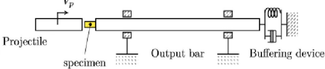
This device is composed of a transmitted bar, a projectile and three Wheatstone bridges of double gauges mounted on the bar for the measurement of deformations and dispersion monitoring (Figure 1). The transmitted bar is 1.2m length and 10 mm diameter. Four projectiles of diameter 15.8 mm and lengths of 500 mm, 125 mm, 60 mm and 30 mm respectively are used.
Figure 1: direct impact device
The higher the objective strain rate is, the lower the length of the projectile must be to avoid crushing the specimen. The bar and the projectiles are made of MARVAL X2NiCoMo18-8-5, with a yield stress of 1800 MPa. The impact velocity of the projectile is measured by two laser diodes. For each objective strain rate, the value of the specimen length 𝑙𝑠, the projectile length 𝑙𝑝 and its impact velocity 𝑣𝑝 should be determined. The
maximum values of the expected strain rate 𝜀𝑠̇ and the allowable strain 𝜀𝑠 in the specimen can be approximated by the following equation:
𝜀̇𝑠𝑚𝑎𝑥 ≈ 𝑣𝑝
𝑙𝑠 𝜀𝑠𝑚𝑎𝑥 ≈ 𝜀𝑠̇ 2𝑙𝑝
𝑐𝑝 (1)
where 𝑐𝑝 denotes the sound speed in the projectile. 𝑐𝑝 is defined by the equation E/
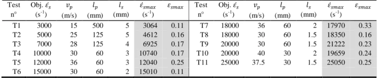
.E and are respectively the Young’s modulus and the density of the projectile material. The parameters for each objective strain rate (Obj. S) are listed in Table 1.
Test n° Obj. 𝜀𝑠̇ (s-1) 𝑣𝑝 (m/s) 𝑙𝑝 (mm) 𝑙𝑠 (mm) 𝜀̇𝑠𝑚𝑎𝑥 (s-1) 𝜀𝑠𝑚𝑎𝑥 Test n° Obj. 𝜀𝑠̇ (s-1) 𝑣𝑝 (m/s) 𝑙𝑝 (mm) 𝑙𝑠 (mm) 𝜀̇𝑠𝑚𝑎𝑥 (s-1) 𝜀𝑠𝑚𝑎𝑥 T1 3000 15 500 5 3064 0.11 T7 18000 36 60 2 17970 0.33 T2 5000 25 125 5 4612 0.16 T8 18000 30 60 1.5 18350 0.16 T3 7000 28 125 4 6925 0.17 T9 20000 30 60 1.5 21222 0.23 T4 10000 30 60 3 10740 0.17 T10 20000 40 30 2 19659 0.24 T5 12000 36 60 3 12040 0.25 T11 25000 37.5 30 1.5 25050 0.25 T6 15000 30 60 2 15010 0.11
Table 1: experimental plan and results
The elastic strain 𝜀𝑏(𝑡) in the transmitted bar and the impact velocity 𝑣𝑝 of the projectile are measured. From the recorded strain 𝜀𝑏(𝑡), the force 𝐹𝑠(𝑡) applied by the projectile on
the specimen is computed by:
𝐹𝑠(𝑡) = 𝐸𝑏𝑆𝑏𝜀𝑏(𝑡) (2)
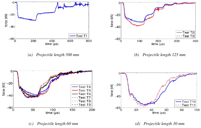
where 𝐸𝑏 is the Young’s modulus and 𝑆𝑏 is the cross-section of the bar. The results are plotted in Figure 2. The trays observed during the unloading part of these curves arise from the shorter length of the projectile than that of the bar and the mismatch of the generalized wave impedances between the projectile 𝑍𝑝 = (𝜌𝑐𝑆)𝑝, the specimen 𝑍𝑠 = (𝜌𝑐𝑆)𝑠 and the
bar 𝑍𝑏= (𝜌𝑐𝑆)𝑏 (Wang 2007).
When the projectile is long enough, the loading time and the characteristic time are equivalents, as we can see in the Figure 2(a) where the projectile is 500 mm length. As the projectile shorten the actual period of loading of the specimen lasts approximately twice the characteristic time or even longer as is observed in Figure 2(b) and Figure 2(d), these results from the different cross-sections of the projectile and the bar. Following this, the specimen undergoes a second compression before the unloading starts. Thus, it is subjected to a higher strain than that of the test T1 as shown in the Table 1, even though the projectile of the test T1 has a greater kinetic energy before impact.
For the direct impact device, the strain rate in the specimen is assessed by the following equation (Gorham et al. 1992; Guo et al. 2014):
𝜀̇𝑠(𝑡) = −
𝑣𝑝+𝑆𝑝+𝑆𝑏
𝑆𝑝 𝐶𝑏𝜀𝑏(𝑡)
𝑙𝑠 (3)
where 𝑆𝑝 is the cross-section of the projectile and 𝐶𝑏 the sound speed of the bar. The maximum compressive strain rate 𝜀̇𝑠𝑚𝑎𝑥 computed by using this equation and the measured compressive strain 𝜀𝑠𝑚𝑎𝑥 for each test are listed in Table 1. This equation states that the compressive strain rate gets its maximum equal to 𝑣𝑝/𝑙𝑠 at the beginning of the impact and is however only valid during the characteristic time (Gorham et al. 1992).
The stress-strain curves are computed using the classical analysis of the Hopkinson tests (Guo 2015). The results are shown in the Figure 3. As the strain rate increases, the curves exhibit a rising strain hardening. However, they are subjected to scattering, as we can observe through small oscillations. Consequently, the rate dependency is difficult to be
7th International Conference on High Speed Forming – 2016
assessed on these curves directly. An inverse analysis is carried out for the identification of the constitutive models.
(a) Projectile length 500 mm (b) Projectile length 125 mm
(c) Projectile length 60 mm (d) Projectile length 30 mm
Figure 2: Force on specimen in the direct impact tests
(a) Projectile length 500 mm (b) Projectile length 125 mm
(c) Projectile length 60 mm (d) Projectile length 30 mm
3 Inverse identification of elastic-viscoplastic constitutive
models
The elastic-viscoplastic constitutive models used to represent the behavior of the material must be able to fit correctly the experimental measurements. They are identified by an inverse procedure that uses a dynamic numerical analysis. No thermal effect is addressed in these identifications. Three models that fit well to this requirement have been chosen:
a) The Johnson-Cook model (Johnson & Cook 1983)
𝜎(𝑝, 𝑝̇) = (𝐴 + 𝐵𝑝𝑛)(1 + 𝐶𝑙𝑛 𝑝̇
𝑝̇0) (4)
where p and 𝑝̇ are the cumulated plastic strain and strain rate respectively. The parameters
A, B and n are obtained by quasi-static classical tension test [10]: A=955 MPa, B=770 MPa
and n=0.557. The parameter C is the only one to be identified by the inverse process. An axisymmetric 2D Finite Element model in ABAQUS is used to compute the dynamic simulation. The model consists of the projectile, the specimen and the bar.
b) The Zerilli-Armstrong model (Zerilli & Armstrong 1996)
This model is calibrated using a unidimensional FE model in MATLAB developed in (Andriamiseza 2014). Assuming a constant temperature T, two variants for bcc and hcp materials are considered in Eq. 5 and Eq. 6 respectively:
𝜎𝑦 = 𝐾0+ 𝐾1𝑝𝑛+ 𝐾
2𝑝̇𝐾3 (5)
where 𝐾0 = 𝐶0, 𝐾1 = 𝐶5, 𝐾2= 𝐶1exp(−𝐶3𝑇) and 𝐾3= 𝐶4𝑇. The parameters, 𝐾0, 𝐾1 and
𝑛 have the same value as the parameters A, B and n of the Johnson-Cook relation because of the equivalent form of strain hardening. The parameters 𝐾2 and 𝐾3 have been calibrated inversely.
𝜎𝑦 = 𝐾0+ 𝐾1𝑝̇𝐾2 + 𝐾3√𝑝𝑝̇𝐾4 (ℎ𝑐𝑝) (6)
where 𝐾0= 𝐶0, 𝐾1= 𝐶1exp(−𝐶3𝑇) , 𝐾2= 𝐶4𝑇, 𝐾3= 𝐶2exp(−𝐶3′𝑇) and 𝐾
4= 𝐶4′𝑇.
𝐾0 is equivalent to the yield stress. Four parameters 𝐾1, 𝐾2, 𝐾3 and 𝐾4 are computed during
the inverse identification.
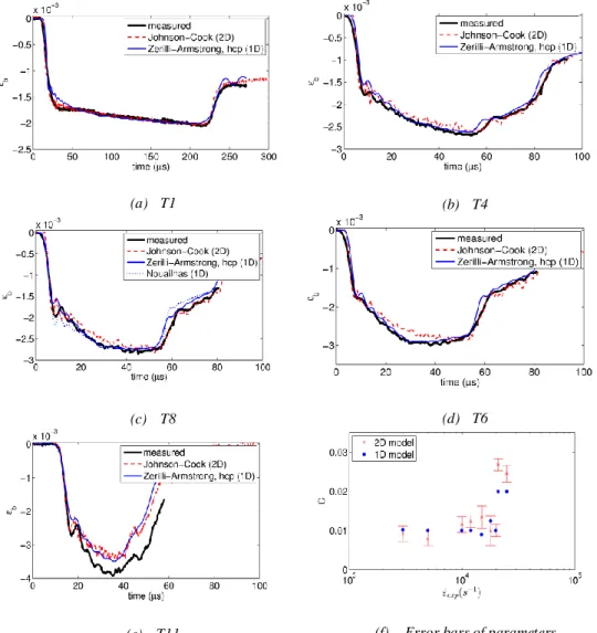
The cost function 𝑓(𝑥) is defined as the Euclidean norm of the difference between the simulated strain 𝜀𝑠𝑖𝑚(𝑥, 𝑡) and the recorded strain 𝜀exp(𝑡). The identification is done on each tests of the Table 1. The calibrated strain 𝜀𝑠𝑖𝑚 of the tests T1, T4, T6, T8 and T11 are plotted and superposed to the measured strain 𝜀𝑒𝑥𝑝 in the
7th International Conference on High Speed Forming – 2016
Figure 4(e). An error bar is plotted associated to each mean value of the parameter C for the 2D identification, as shown in the
Figure 4(f). At least two repetitions are carried out for each test. The simulated strains of the three different constitutive models fit well to the experimental data at strain rate up to 15000 𝑠−1. We observe at the second raising stage when the specimen is plastically
deformed that the results are concordant as shown in the Figure 4(a)-
Figure 4(c). A small difference appears at this stage between the calibrated strain of the Johnson-Cook model and the measured one in the
Figure 4(d). The Zerilli-Armstrong model fits well the experimental data. The
Figure 4(f) indicates that an approximately constant value of the parameter C of the Johnson-Cook model is identified at the strain rate ranging from 3000 to 18000 𝑠−1. At
very high strain rate as observed in the tests T10 and T11, a much greater value of C is obtained. The differences in these two tests may be due to (i) the very short projectile used in the test and/or (ii) the thermal effects not addressed in the identification. More repetitions of these tests must be carried out to clarify the results.
(a) T1 (b) T4
(c) T8 (d) T6
Figure 4: Results of identifications
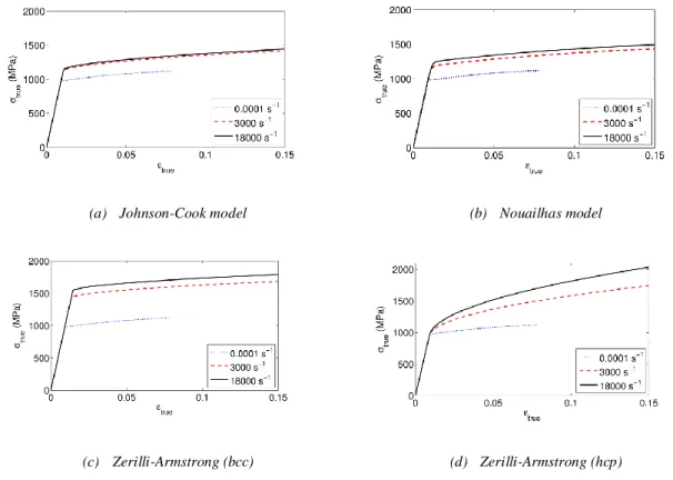
The stress-strain curves of the identified constitutive models are plotted at the strain rate of 3000 𝑠−1 and 18000 𝑠−1 and are compared to those obtained from the quasi-static tests in
the Figure 5. The Figure 5(a)-Figure 5(c) show a great raise of the flow stress as the strain rate is increased. This increase is lower when the strain rate goes from 3000 to 18000 𝑠−1.
For the Johnson-Cook model, the two curves at these two strain rates are very close in the
Figure 5(a). Similar observations can be done for the other models.
(a) Johnson-Cook model (b) Nouailhas model
(c) Zerilli-Armstrong (bcc) (d) Zerilli-Armstrong (hcp)
Figure 5: stress-strain curves plotted within the range of 10-4 to 18000 s-1
4 Conclusion
In this work, the Ti-6Al-4V has been tested on a range of strain rate ranging from 3000 to 25000 𝑠−1 using the direct-impact Hopkinson device. To identify three elastic-viscoplastic
constitutive models, an inverse analysis has been carried out on the experimental data. The three identified constitutive models fit well the experimental data at the strain rate ranging from 3000 up to 18000 𝑠−1. However more experimental and numerical research at higher
7th International Conference on High Speed Forming – 2016
References
Andriamiseza, A., 2014. Rapport de stage de Master: Identification de modèles de
comportement à haute vitesse de déformation sur des essais de Kolsky à impact direct,
Davies, R.M., 1948. A critical study of the Hopkinson Pressure Bar. Philosophical
Transactions of the Royal Society of London. Series A. Mathematical and Physical Sciences, 240(821), pp.375–457.
Dharan, C.K.H. & Hauser, F.E., 1970. Determination of stress-Strain characteristics at very high strain rates. Experimental Mechanics, 10(9), pp.370–376.
Gorham, D.A., Pope, P.H. & Field, J.E., 1992. An improved method for compressive stress-strain measurements at very high strain rates. Philosophical Transactions of the
Royal Society of London. Series A. Mathematical and Physical Sciences, 438(1992),
pp.153–170.
Guo, X. et al., 2014. Inverse identification at very high strain rate of the Johnson--Cook constitutive model on the Ti-6Al-4V alloy with a specially designed direct-impact Kolsky bar device. Strain, 50(6), pp.527–538.
Guo, X., 2015. On the directimpact Hopkinson system for dynamic tests at very high strain
rates. Ecole centrale de Nantes.
Johnson, G.R. & Cook, W.H., 1983. A constitutive model and data for metals subjected to large strains, high strain rates and high temperatures. 7th International Symposium on
Ballistics, pp.541–547.
Kamler, F., Niessen, P. & Pick, R.J., 1995. Measurement of the behaviour of high-purity copper at very high rates of strain. Canadian Journal of Physics, 73(5--6), pp.295– 303.
Kolsky, H., 1949. An investigation of the mechanical properties of materials at very high rates of loading. Proceedings of the Physical Society. Section B, 62.
Ramesh, K.T., 2008. Part D: Chapter 33. High strain rate and impact experiments. In
Springer handbook of experimental solid mechanics. Springer, pp. 1–31.
Wang, L., 2007. Foundations of stress waves, Elsevier BV.
Zerilli, F.J. & Armstrong, R.W., 1996. Constitutive relations for titanium and Ti-6Al-4V. In Proceedings of the conference of the American Physical Society topical group on