HAL Id: hal-02110117
https://hal.archives-ouvertes.fr/hal-02110117
Submitted on 16 Mar 2020HAL is a multi-disciplinary open access archive for the deposit and dissemination of sci-entific research documents, whether they are pub-lished or not. The documents may come from teaching and research institutions in France or abroad, or from public or private research centers.
L’archive ouverte pluridisciplinaire HAL, est destinée au dépôt et à la diffusion de documents scientifiques de niveau recherche, publiés ou non, émanant des établissements d’enseignement et de recherche français ou étrangers, des laboratoires publics ou privés.
A New Concept of Functional Energetic Modelling and
Simulation
Mert Mokukcu, Philippe Fiani, Sylvain Chavanne, Lahsen Ait Taleb, Cristina
Vlad, Emmanuel Godoy, Clement Fauvel
To cite this version:
Mert Mokukcu, Philippe Fiani, Sylvain Chavanne, Lahsen Ait Taleb, Cristina Vlad, et al.. A New Con-cept of Functional Energetic Modelling and Simulation. Proceedings of The 9th EUROSIM Congress on Modelling and Simulation, EUROSIM 2016, The 57th SIMS Conference on Simulation and Mod-elling SIMS 2016, Sep 2016, Oulu, Finland. pp.582-589. �hal-02110117�
A New Concept of Functional Energetic Modelling and Simulation
Mert Mokukcu
1,2Philippe Fiani
1Sylvain Chavanne
1Lahsen Ait Taleb
1Cristina Vlad
2Emmanuel Godoy
2Clément Fauvel
31Sherpa Engineering, France, {m.mokukcu,p.fiani,s.chavanne,l.aittaleb}@sherpa-eng.com
2Automatic Control Department, Laboratoire des Signaux et Systèmes (L2S, UMR CNRS 8506)
CentraleSupélec-CNRS-Université-Paris-Sud, France, {cristina.vlad,emmanuel.godoy}@centralesupelec.fr
3 IRCCyN, UMR-CNRS 6597, Ecole des Mines de Nantes, IMT, France, [email protected]
Abstract
In this study a new concept of functional modelling and simulation is introduced. First, the necessity and the expected outcomes of the new concept are explained. Secondly, the methodology of functional modelling based on a modular concept and the basic elements are presented, with details of OFS (Organico Functional Set). Then, the implementation of the new modelling concept using Sherpa Engineering’s PhiSim environment is described in order to perform simulations. Finally, the proposed modelling method is applied to two different applications: a generic parallel hybrid electric vehicle (HEV) and a waste water treatment unit of a building. Simulation results of parallel HEV application are also presented.
Keywords: electric vehicles; functional modelling; functional model simulation; hybrid vehicles; waste water treatment unit
1
Introduction
The economic and ecological context drives industries and academic research to investigate how systems can be optimally designed with respect to their local and global energy efficiency (Arnal et al., 2011; Mouhib et al., 2009; Sherpa Engineering, 2016; Wirasingha et al., 2011). Due to the quick progress and the variety of energy technologies and energy management strategies, being able to numerically simulate a solution has become a crucial aspect of the system design process (Haveman et al., 2015). Usually, this step requires a model of the system and a simulation environment. So far, the Bond Graph theory introduced by Karnopp and Rosenberg has been widely promoted in industrial and academic communities to model multi-physic systems (Karnopp et al.,1983).
Basically, this approach is based on effort and flow interactions and uses phenomenological analogies to represent any nature of systems (i.e. mechanics, electrics, etc.). The obtained model can subsequently be used for system analysis and design of optimal control laws (Bideaux et al., 2006; Otter et al., 1996). This philosophy forms the base of several commercial multi-physics modelling tools as AmeSim, Dymola or PhiSim
(Marquis-Favre et al., 2006; Pénalva et al., 1994; Sciarretta et al., 2007). However, these tools allow only constructional design, i.e. the representation of the organic level of a system.
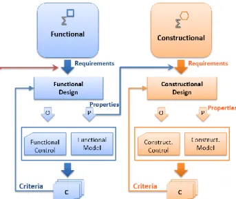
In his studies, (Von Bertalanffy, 1968) remarked that some systems, referred as complex systems, contain many interactions with themselves and their environment that should be designed with a unique level of abstraction (Eriksson, 1997; Le Moigne, 1994). In addition to constructional design, the use of functional approach in system modelling has been largely supported by most of complex systems specialists (Le Moigne’s modelling theory (Eriksson, 1997; Le Moigne, 1994), Sagace methodology (Sciarretta et al., 2007) and axiomatic design (Suh, 1998)). This approach defines a higher abstraction level than for constructional design (see Figure 1) and does not need the organic elements definition. The system is modelled through functionalities which are interacting in order to achieve a certain purpose referred as system mission. Therefore, it can be used in early stage development to simulate the system architecture. However, the framework to be used (i.e. equations, variables flows) is currently an open problem, especially for energetic systems.
Figure 1. Functional and constructional (organic)
The difficulties encountered in these multiple level models are mainly the following: how to define the model and its parameters when the equipment does not yet exist, and how to avoid the adjustment of the entire energy supervision system (responsible for an optimal energy flow) at each modification of the architecture. These difficulties increase the time required to model and analyse the simulation results leading either to a reduced number of potential solutions or to a laborious design process. Confronted by these challenges, it has become essential to develop a new tool-based methodology, also based on modelling, that uses the necessary level of abstraction by integrating modular functional models and optimization algorithms.
A first step towards the formulation of a functional design language for energetic systems has been made with PhiGraph introduced in (Brunet et al.,2005). However, interactions consist of effort and flow exchanges, as in Bond Graph theory, and belong to the organic level of a system. Therefore, PhiGraph cannot be related to a full functional language. This is why a new concept of functional modelling language and method is proposed.
The expected outcomes of the proposed functional modelling method are:
• Fast simulation and evaluation of the system concept before choosing the technology;
• Simulation of the system as a whole: physics and control;
• Obtaining a supervisor for the organic simulation model;
• Make connections between modelling and simulation in multi-physic systems.
In our previous work (Fauvel, 2015), two functional elements were introduced: a consumer and a source, which are exchanging needs and availability information. This has led to a fully functional framework which was initially applied to formulate an energy management problem (Fauvel et al., 2014). This paper extends the concept of consumers and sources ports to a complete simulation language for energetic systems by considering five functional elements described in Section 2. Its potential is highlighted by modelling and simulating two classic applications in Section 3. Conclusion and perspectives of this work are given in Section 4.
2
Functional Modelling Methodology
The base concept of the proposed functional modelling method is to provide a functional link between two systems, which can be described as an exchange in terms of energy (mechanical, electrical, hydraulic, thermal,
etc.), matter (fluid, solid, etc.) and information (set point, measurement, etc.). In the early steps of system
design, this exchange and its nature have to be defined for two sub-systems or for a system and its environment. In constructional or organic level of modelling like Bond Graph or PhiGraph, inputs and outputs of the components depend on flow/effort of physical domain. Unlike the organic level, the functional level uses three types of flow: energy, matter and information, each of them being decomposed in a triadic basis. In Table 1, the transformation natures of functional level are presented.
Table 1. Transformation Natures of Functional
Modelling.
T Time
Transformation Storage, Accumulation
S Space Transformation Transport, Transmission, Distribution, Injection, Extraction F Form Transformation Transformation, Conversion, Production, Destruction, Consumption
2.1 Modular Concept
In a controlled complex system, the exchange between different functions is governed by a certain need. For example, in order to drive at a given speed, the vehicle motion functionality (Mobility) needs power flux. If the need is not expressed, there is no reason to supply power to Mobility. In the proposed methodology, the need has dominant causality with respect to the energy/matter supply. On this basis, the functional modelling method is developed from the following question: Who
transmits a need, and to whom?
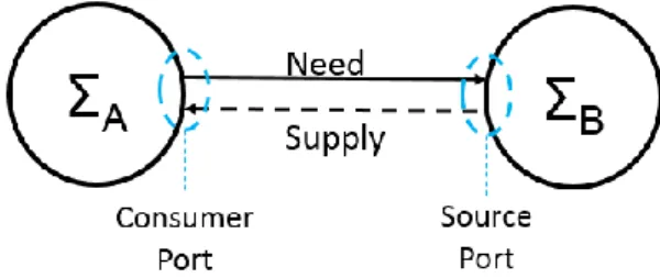
This methodology introduces two types of ports: source port, which supplies an energy/matter flux as an answer to an expressed need, and consumer port, which receives energy/matter flux also as an answer to a specified need. In Figure 2 the source and consumer ports between two systems are introduced. In order to highlight the dominance of a causality requirement, Figure 2 illustrates the functional link with a single arrow, which expresses the necessity of causality. The arrow direction indicates where the need is transmitted, regardless its value (positive/negative) or the direction of supply. Furthermore, at this level of abstraction, it is not necessary to specify the physical domain associated with the need, but it can be done for information.
Figure 3 presents the functional links for a system with three sources and their associated source and consumer ports. The energy distribution in the system is made by distribution elements, represented by grey bars, and that will be introduced in Section 2.2.4.
Figure 3. A system example with multiple source and
consumer ports.
In the proposed concept, all elements use simple equations from these transformation natures. Some examples of equations can be introduced as: energy (1) and dynamics (2) of time transformation nature, efficiency (3) of form transformation nature and power balance (4) of space transformation nature:
𝐸 = ∫ 𝑃 (1)
𝑌(𝑠) = 𝐻(𝑠)𝑈(𝑠) (2)
𝜌 = 𝜌(𝜇, … ) (3)
∑ 𝑃𝑡 (4)
Equations are used to define internal properties of different elements: the integral of power is used for storage elements, transfer functions for effector elements, efficiency for transformation elements and power balance equation for distribution elements.
2.2 Adequate Language in Modelling Level
In this section, basic elements of functional modelling are described. These elements are: source, storage, transformation, distribution and effector, classified as in Table 2. Generally, all functional elements are based on two blocks: control system block (upper block) and operating system block (lower block), usually represented respectively in green and blue colors as shown in Figure 4(a).
Figure 4. Representations of (a) generic and (b) source
elements.
A generic element is a black box that has its own control and operating systems. The control system manages the operation according to the demands, actions and constraints. On the other hand, the operating system represents the physical behaviour of the function.
Table 2. Element Types of Functional Energetic
Modelling.
Source Storage Transformation Distribution Effector
Energy & Matter Source Energy & Matter Storage
Energy & Matter Transformation in Different Domains Energy & Matter Distribution Represents Energetics Services 2.2.1 Source
The source (e.g. fuel station, electrical grid) represents the supply of energy/matter to meet the consumer needs. Within the physical limits of the source, the control system is intended to compute the provided power Pcons
in response to the received need Ncons, illustrated in
Figure 4(b). If losses are considered, the source also contains Ploss port.
As a consequence of many possible sources, the operating system behaviour is not generic. In the simplest case, the source is infinite like an electrical grid, where the only feature that defines the maximum power is the received or the supplied power. In a more specific case, such as a brake system, which can be represented by a negative power source, the maximum power that can be dissipated depends on its organic characteristics (maximum torque etc.).
2.2.2 Storage
A storage (e.g. battery, fuel tank) represents a given energy/matter storage which engages availability for an answer (Pcons) to a need of consumption (Ncons) and for
its own need (Ncharge) to charge (Pcharge), to keep its state
of charge (SOC) at an adequate level. If necessary, the settings of this block can be customized for a particular type of storage. For example, the maximum energy that can be stored in a fuel tank is linked to its volume, which does not exist for a battery.
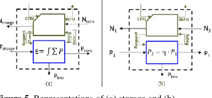
In Figure 5(a), the representation of the storage elements is given, which has a simple operating system behavior. The stored energy/matter level is achieved by integrating the balance of incoming-outgoing powers, while considering the capacity limitations of the storage
(the maximum power that can be received or supplied). Exceeding these limitations may result in losses (Ploss).
The equation adopted to represent the behavior of the operating system is quasi-generic.
Figure 5. Representations of (a) storage and (b)
transformation elements.
2.2.3 Transformation
The transformation element (e.g. electric machine, internal combustion engine (ICE), converter) offers need and power transfer between two functional elements. It takes given efficiency into consideration and it also allows domain change (e.g. fuel to mechanical). Figure 5(b) illustrates the representation of the transformation element.
The control system of transformation converts the received need (N2) into need delivered (N1) with a
specified efficiency. Transmitted power (P2) is derived
from the received power (P1) regarding any limitations.
The difference between P1 and P2 ports defines the
power losses. The transformation element is also characterized by a quasi-generic equation.
2.2.4 Distribution
The distribution element of functional modelling can be seen as a connector of multiple sources and consumers. This element has two main tasks: distribution of consumer needs (Nk, Nl, Nm) to sources (Ni, Nj) and
distribution of supplied power/matter (Pi, Pj) to
consumers (Pk, Pl, Pm). Distributions are allowed by
taking into account the constraints specific to each source and consumer. The representation of distribution is given in Figure 6(a). Distributions respect the balance equation of energy/matter, based on the principle that there are no losses or storage in normal operation. Moreover, they connect the ports of same nature.
The distribution control system is more complex because of management of multi-sources/multi-consumers. The designer’s task is to choose the most appropriate algorithm that will assure optimal power distribution with respect to system requirements and physical limits. The distribution constraints are related to the source availability, the consumer priorities and the evolving distribution method.
2.2.5 Effector
The effector element is associated with the achievement of an objective. In order to achieve its objective, the effector transmits a power need (Ncons). Accordingly, it
receives power (Pcons) to execute its function. Figure
6(b) indicates the need generation and the power reception.
The effector is the heart of the functional modelling architecture since it generates the need. Without effector there is no need, therefore no functional architecture design can be made. The control system is intended to compute the power need to achieve the objective. Furthermore, the operating system is not generic because of the great variety of its objective and execution (i.e. for thermal comfort, temperature value can be obtained from heat equation).
Figure 6. Representations of (a) distribution and (b)
effector elements.
2.3 Details of Functional Energetic
Modelling Method
OFS is a generic element (Figure 7(a)) that can be used to represent all five elements introduced in the previous section. For example, a vehicle can be represented as two interconnected OFS, one to represent fuel source and a second model for mobility effector (Figure 7(b)).
Generally, the input arrow is connected to a source port of OFS and the output arrow is connected to a consumer port of OFS. If wanted, arrow colours could be used as domain instructors as red for electric, green for mechanic and blue for hydraulic. At the top of the element, the green box offers an information link between the OFS and the supervisor, which is a global controller of the system. Finally, the ground symbol placed at the bottom of the representation corresponds to losses that will not be recycled. To recover losses, an additional source port could be used.
Figure 7. (a) Representation of OFS and (b) example
PhiSim link.
3
Implementation to Simulation
Environment
This section describes the implementation of energetic and functional modelling elements in PhiSim, an environment developed by Sherpa Engineering to define
and simulate the proposed functional model. Sherpa Engineering proposes PhiSim as a modelling and simulation environment for physical systems using Matlab/Simulink software that allows generating models and their control in a multiport environment (Sherpa Engineering, 2016).
3.1 Simulation Tool Integration
Two different types of standardized ports are considered: source port and consumer port. Source port receives consumer power need, availability, acceptances of power and energy/matter from connected consumer. The source port also transmits provided power, availability, acceptances of power and energy/matter to the connected consumer.
The elements are connected based on the following principles:
• Communication between elements and supervisor is possible using a bidirectional link of control/information (CTRL/INFO);
• Two elements are interconnected by a bidirectional link of need/supply (N*, P*);
• Losses port of an element is defined as an output port that does not require an input (it refers to losses without an associated need);
• The direction of arrows indicates where the need is transmitted regardless its sign.
Availability and acceptancy information are useful for the (local or global) control. For example, to distribute a need of a consumer to multiple sources, distribution must check the sources availability. For instance, a consumer is available to receive negative power which is provided by a source that has acceptance.
It is important to highlight the role of the distribution element for the intelligence system and the energy management strategy. For the moment, power need for each consumer is treated using priorities. Total power need is spread across different sources and prioritized according to their availability and acceptance. If total power need cannot be fully allocated, the remaining power need is allocated to the source that has first priority.
3.2 Examples from Different Domains
The functional modelling methodology presented in the previous sections is applied to two complex systems from different fields of applications, showing the general character of the proposed modelling formalism and the capacity to easily adapt to various systems. The considered applications are: a parallel hybrid electric vehicle (HEV) and a waste water treatment unit of a building.
For the first example, the objective is to evaluate the consumption of a parallel HEV with respect to a specific power load profile. In order to analyze the power flow in the system, the vehicle dynamics has to be considered, as well as the electrical auxiliaries and the braking system. All these elements lead to a complex organic model which will increase the simulation time and the design procedure: architecture choice, supervisor construction, component choice and sizing.
Using the functional modelling approach, the elements of the parallel HEV architecture are represented by elements described in Section 2.2. The implementation of the functional model in PhiSim is given in Figure 8.
A standard driving cycle, NEDC (New European Driving Cycle), is chosen to analyse the architecture of the parallel HEV using a functional model that can be simulated.
The simulation model of the hybrid vehicle consists of:
• Three energy distribution elements (Distribution), • Three transformation elements (F2M, M2E and
E2M),
• Two storage elements (Fuel and Electric),
• Two effector elements (Electrical auxiliary and Vehicle motion).
A special functional element is employed for the braking system, which can act as a source or an effector for different driving modes. The simulation results of this application are given in Section 3.3.
The second complex system is a waste water treatment unit of a building. The objective of this application is to calculate the cold and hot water consumption for a real scenario and also to provide the equivalent power consumption and cost estimation. The difference with the parallel HEV is in the flow type used: matter and energy instead of energy.
Figure 9. Waste water treatment unit functional model.
In this case, the functional model is obtained based on a reduced organic model with a real scenario of grey water treatment unit (GWTU) from a hotel. The functional model of the waste treatment unit is given in Figure 9 and Figure 10.
The model consists of the following elements: • Two transformation elements (Treatment unit and
Consumption),
• A storage element (Recovery as water tank), • Two distribution elements,
• Two source elements (Rain and Water grid), • A system of water distribution unit (see Figure 10)
of a building.
Figure 10. Waste water distribution unit functional
model.
The water distribution unit is modelled by:
• Three transformation elements (Hot and Cold water conditioning and Exchanger),
• Two storage elements (Hot and Cold water tanks), • Two distribution elements (Mixer and Water
distribution unit).
As it can be seen from both examples, functional modelling representation and simulation can be applied to different domains and natures. For example, for HEV application the flow nature is either energy or information, whereas in GWTU application, in addition to energy, matter flow is used. However, information is always used as a flow nature in order to have a supervisor that manages the energy flow of the designed system. Therefore, the functional model of the system is thought to be used as a supervisor of the organic model.
3.3 Parallel HEV Example Simulation
Results
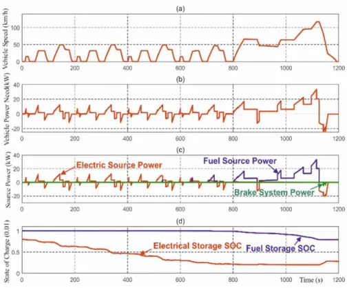
The simulation results of the parallel HEV are represented in Figure 11. As equations used in the proposed functional modelling method are quite simple, the design time is significantly reduced for a preliminary analysis and a full driving cycle can be simulated in a few seconds.
• The first figure (Figure 11(a)) shows that the speed of the parallel HEV is consistent with the NEDC profile.
• The result can be validated as vehicle power needs (Figure 11(b)) and source power supplies (Figure 11(c)) are appropriate to real time calculations. • In Figure 11(d), the scaled values of the SOC (state
of charge) are presented. Electrical storage and fuel storage SOC can be analysed using the functional model, as well as the sources powers.
T --T - T --T - T T T T T T T --T - T T T T -CT RL INF O P _lo ss 1 2 Water Distribution Unit C T R L IN F O P_l o ss 1 Water Grid CT RL INF O P _lo ss 1 2 Treatment Unit CT RL INF O P _lo ss 1 2 Recovery C T R L IN F O P_l o ss 1Rain CT RL INF O P _ lo s s 1 2 Distribution 2 CT RL INF O P _ lo s s 1 2 Distribution 1 CT RL INF O P _lo ss 1 2 Consumption -T-C T R L INF O P _ lo s s 1 2 1 Mixer C T R L INF O P _ lo s s Hot Water Tank C T R L INF O P _ lo s s 1 2 Hot Water Conditioning CTR L INF O P _ lo s s 1 2 1 2 Exchanger CT RL INF O P _ lo s s 1 1 2 Distribution WDU C T R L INF O P _ lo s s Cold Water Tank C T R L INF O P _ lo s s 1 2 Cold Water Conditioning
These results can give a head start for choosing the system architecture and lead to an organic modelling and its simulation. As mentioned in Section 3.2, the proposed modelling method leads to a supervisor/controller of the organic model with adjustments to its flow natures. For example, for the electrical-to-mechanical transformation element, the functional modelling flow is power. In the organic modelling level, this flow becomes electrical flow or mechanical rotation flow. Thus, a transformation element that adjusts the command flows will be added to the system for the supervisor.
4
Conclusions and Perspectives
A concept of functional modelling is proposed and applied to different complex systems where the flow nature is either energy or matter or both. The functional modelling approach develops a macro model of a complex system that can be easily and quickly simulated using the simulation framework PhiSim.
A short-term perspective of this work is to apply this modelling concept to systems with both energy and matter flows for simulations. The long-term perspective is to improve the intelligence of distributions. So far, distributions use priorities for need and power distribution. The improvement consists in developing a performant algorithm for need/supply distributions capable to optimize all natures of flows, and fast enough in order to minimize the simulation time. For these
reasons, the proposed modelling formalism represents an interesting solution for industrial applications as it allows obtaining relevant results in a first stage of preliminary analysis of the system.
References
E. Arnal, C. Anthierens, and E. Bideaux. Consideration of glare from daylight in the control of the luminous atmosphere in buildings. IEEE/ASME International
Conference on Advanced Intelligent Mechatronics (AIM), Budapest, Hungary, pages 1070–1075, 2011. doi:
10.1109/AIM.2011.6027070.
E. Bideaux, J. Laffite, W. Marquis-Favre, S. Scavarda, and F. Guillemard. System design using an inverse approach: Application to the hybrid vehicle powertrain. Journal
Européen des Systèmes Automatisés (JESA), Lavoisier,
40(3):269–290, 2006. doi: 10.3166/jesa.40.269-290. J. Brunet, L. Flambard, and A. Yazman. A hardware in the
loop (HIL) model development and implementation methodology and support tools for testing and validating car engine electronic control unit (ECU). International
Conference on Simulation Based Engineering and Studies, TCN CAE, Lecce, Italy, 2005.
D. Eriksson. A principal exposition of Jean-Louis Le Moigne’s systematic theory. Cybernetics and Human
Knowing, 4(2-3):33–77, 1997.
C. Fauvel. Approche modulaire de l’optimisation des flux de puissance multi-sources et multi-clients, à visé temps reel.
Automatique/ Robotique, Ecole des Mînes de Nantes, 2015.
doi: tel-01245429.
C. Fauvel, F. Claveau, and P. Chevrel. Energy management in multi-consumers multi-sources system: A practical framework. In Proceedings of the 19th IFAC World
Congress, Cape Town, South Africa, volume 47, pages
2260–2266, 2014. doi:
http://dx.doi.org/10.3182/20140824-6-ZA-1003.02446. S. P. Haveman and G. M. Bonnema. Communication of
simulation and modelling activities in early systems engineering. Procedia Computer Science. Volume 44, pages 305–314, 2015. doi: 10.1016/j.procs.2015.03.021. D. Karnopp and R. Rosenberg. Introduction to Physical
System Dynamics. McGraw-Hill, 1983.
J-L. Le Moigne. La théorie du système général, théorie de
la modélisation, 1994. Edited by ae Mcx, 2006.
Available via
http://scholar.google.com/scholar?hl=en&btnG=Search &q=intitle:No+Title#0.
W. Marquis-Favre, E. Bideaux, and S. Scavarda. A planar mechanical library in the AMESim simulation software. Part II: Library composition and illustrative example.
Simulation Modelling Practice and Theory, 14(2):95–111,
2006. doi: 10.1016/j.simpat.2005.02.007.
O. Mouhib, A. Jardin, W. Marquis-Favre, E. Bideaux, and D. Thomasset. Optimal control problem in bond graph formalism. Simulation Modelling Practice and Theory.
Elsevier B.V., 17(1):240–256, 2009. doi:
10.1016/j.simpat.2008.04.011.
M. Otter, H. Elmqvist, and F. E. Cellier. Modeling of multibody systems with the object-oriented modeling language Dymola. Nonlinear Dynamics, 9(1–2):91–112, 1996. doi: 10.1007/BF01833295.
J. M. Pénalva and E. Page. SAGACE: la modélisation des systèmes dont la maîtrise est complexe. in ILCE’94,
Montpellier, France, 1994.
A. Sciarretta and L. Guzzella. Control of hybrid electric vehicles, IEEE Control Systems, 27(2):60–70, 2007. doi: 10.1109/MCS.2007.338280.
Sherpa Engineering. Phisim Brochure, Paris, France. Available at: www.sherpa-eng.com. [accessed January, 2016].
N. P. Suh. Axiomatic Design Theory for Systems.
Research in Engineering Design, 10(4):189–209, 1998.
doi: 10.1007/s001639870001.
L. Von Bertalanffy. General System Theory. Georg.
Braziller New York, 1968. Available via:
http://books.google.es/books?id=N6k2mILtPYIC. S. G. Wirasingha and A. Emadi. Classification and review
of control strategies for plug-in hybrid electric vehicles.
IEEE Transactions on Vehicular Technology,


![[PDF] Formation avancé sur la Méthode de Conception des Systèmes d'Information Merise](data:image/gif;base64,R0lGODlhAQABAIAAAP///wAAACH5BAEAAAAALAAAAAABAAEAAAICRAEAOw==)