HAL Id: hal-01008070
https://hal.archives-ouvertes.fr/hal-01008070
Submitted on 18 May 2018
HAL is a multi-disciplinary open access
archive for the deposit and dissemination of
sci-entific research documents, whether they are
pub-lished or not. The documents may come from
L’archive ouverte pluridisciplinaire HAL, est
destinée au dépôt et à la diffusion de documents
scientifiques de niveau recherche, publiés ou non,
émanant des établissements d’enseignement et de
Development of normalized impact test of rubber
projectiles on laminate composite panels
Pierrick Guégan, Ramzi Othman, Daniel Lebreton, Franck Pasco, Nicolas
Swiergiel, Pascal Thévenet, Benoît Malherbe, Jean-Jacques Maffre
To cite this version:
Pierrick Guégan, Ramzi Othman, Daniel Lebreton, Franck Pasco, Nicolas Swiergiel, et al..
Develop-ment of normalized impact test of rubber projectiles on laminate composite panels. DYMAT 2009,
2009, Bruxelles, Belgium. �10.1051/dymat/2009075�. �hal-01008070�
Development of normalized impact test of rubber projectiles
on laminate composite panels
P. Gue´gan
1, R. Othman
1, D. Lebreton
1, F. Pasco
1, N. Swiergiel
2,
P. Thevenet
2, B. Malherbe
3and J. Maffre
31
Institut de Recherche en Ge´nie Civil et Me´canique (GeM), E´cole Centrale Nantes, 1 rue de la Noe¨, BP. 92101, 44321 Nantes Cedex 3, France
2
EADS IW, 12 rue Pasteur, BP. 76, 92152 Suresnes Cedex, France 3
AIRBUS France, 316 route de Bayonne, 31060 Toulouse Cedex 03, France
Abstract. This paper aims at presenting an experimental set-up for testing rubber projectiles impact on laminate composite panels. The test boundary conditions must be mastered to obtain good cor-relation between experimental and numerical results. A spherical projectile, which is 42 mm in dia-meter, is launched by a nitrogen gas thrower, at a velocity in the range 100–150 m/s. As the canon has an inner diameter of 100 mm, a geometrical adapter made of polymeric foam is used. The target
is a square panel (500r500 mm). The experimental set-up allows changes in the impact angle
be-tween 20 and 90x with a step of 5x. The projectile velocity is measured by a laser and diode system. The impact zone is filmed by two high speed video cameras. The experimental set-up is instru-mented with twelve strain gage stations. Furthermore, the target is borne by a supporting frame of square section. The link between the target and the supporting frame can be represented by a simple contact. In addition, it doesn’t block the rebound of the projectile for all impact angles. Finally, the supporting frame doesn’t oppose rotation movements. The target and its supporting frame are fixed on a bearing structure. It is constituted by two half squares and of two lateral elliptical support. In this paper we will detail the experimental set-up and give some results obtained by impacting composite panels with rubber spherical projectiles.
1. INTRODUCTION
Safety is one of the important interests in transportation design. Therefore, in recent decades many works interested in developing and studying crashworthiness structures [1, 2]. However, there are still some aspects to be investigated. For example, in airplane industry, it is of major importance to assess the response of wings to the impact of rubber tire debris. The basic solution consists in the experimentation with true tyre debris on real wing panel, but the investigations are expensive, the results not mastered and with difficulty of extrapolation [3]. A better solution is the numerical simulation [4]. The study can be easily realized, for several configurations. But initially, the numerical model must be validated by experimental results (based on elementary test con-figurations), whose limit conditions are mastered as good as possible. These must be easily integrated in the calculation code. Therefore, it is important to measure the response of materials in a wide range of strain-rates [5–8], mainly rubber-like materials [3,9]. Furthermore, it is essential to develop an experimental set-up to study the response of laminated plates to the impact of rubber projectiles, with the control of the boundary conditions. The last point is the goal of this paper.
2. EXPERIMENTAL SET-UP 2.1 General principle
The objective of this study is to develop an experimental set-up allowing to launch a rubber spherical projectile of 42 mm in diameter (mass of 45 g), at velocities in the range of 100–150 m/s.
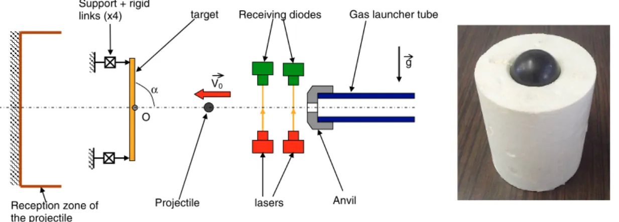
This projectile must hit the centre of a square plate, with sides of 500 mm. The experimental set-up must allow changes in the impact anglea in the range of 20–90x (Figure 1).
To realize this study, we used the gas launcher facility of the Institut de Recherche en Ge´nie Civil et Me´canique (GeM) which is shown on Figure 2. It works with nitrogen. Its high pressure chamber has a volume of 0.033 m3and a maximum inflate pressure of 1000 bar. The canon is a 9-meter long tube with an inner diameter of 100 mm. The maximal velocity is 600 m/s with a 500-g heavy polyethylene projectile. Before impact, the projectile velocity is measured by a system of laser and a receiving diode.
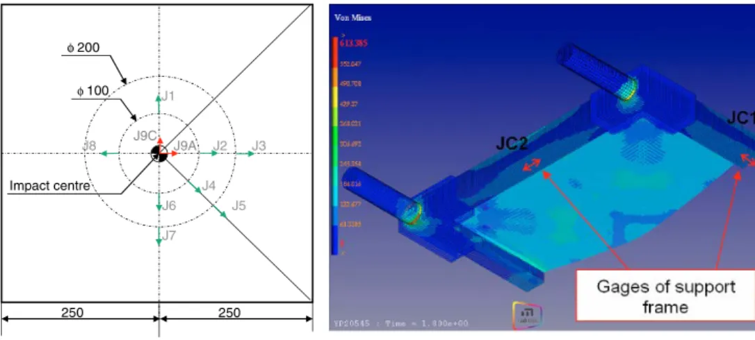
The impact zone is filmed by two high speed video cameras. The first camera (PHOTRON SA1) films the lateral view whereas the second films the impact from the top. This second camera (PHOTRON APX) observes the projectile on the impact and exit side of the target. Therefore, it can be used to obtain the rebound velocity of the projectile when the impact angle value is 90x. In case of perforation, the projectile is recovered after impact in a reception zone (Figure 1). The rear face of the target is instrumented by nine strain gages (Figure 3). Eight gages measure the strain in one direction and are referred to as J1 to J8. The last measures the strain in two directions. The corresponding strains are referred to as J9A and J9C. Furthermore, the supporting frame is instrumented with two simple strain gages, (ref. JC1 and JC2). The gages are connected by two 2200 VISHAY conditioners. Their signals are recorded by a NICOLET digital oscilloscope of 1 MHz frequency. V0 α g Receiving diodes lasers
Gas launcher tube
Projectile target Support + rigid links (x4) Reception zone of the projectile O Anvil
Figure 1. Schema of the experimental set-up, and fusible cylinder adapter with projectile.
In order to guide the projectile in the canon, a geometrical adapter is used. We have chosen to use a fusible cylinder adapter in polyurethane foam (Figure 2). On one of its sides, it includes a centred almost conical cavity, intended to accept the projectile. It is manufactured in our laboratory, by injection in specific moulds. During firing, the geometrical adapter moves through the 9 meters of the tube, before impacting an anvil on the exit side. The fusible adapter is stopped, while the projectile moves outside the tube.
2.2 Technical solution
The adopted methodology allows a positioning of the plate such that the projectile always comes into contact with the target at its center. The target is supported in a frame support of square section. It is linked in its four corners to the building of the assemblage by rigid cells of identical geometry as possibly-added force sensors. In addition, the positioning assembly is constituted of
φ 200 φ 100 250 250 Impact centre J1 J2 J3 J9C J9A J4 J5 J6 J7 J8
Figure 3. Gages distribution on plate and supporting frame.
α
Firing axe Plate
centre
Axes in lateral elliptical support
built of positionin g assembly x
y
z
O Rear half square
(x2)
Bridle of positioning (2+2)
two half squares (for back fixing) and two lateral elliptical supports (for front fixing); the latter are provided with indexations in order to allow impact angles from 20 to 90x with a step of 5x. The mounting frame is fixed in its four corners to the sensors by spindle links. All spindles are locked by clamping to decrease the flexibility of the assemblage. Furthermore, the centre of assemblage is clear to allow the impact of the projectile. The back of the target is also cleared to increase the visibility of the target by cameras, the back sensors (side squares) are oriented to measure compressive stress, the front sensors (side elliptical support) measure tensile stress. The principle schema and the general view of the assembly are showed in Figure 4.
2.3 Boundary conditions of the target
The link between target and the supporting frame should be modelled by a simple contact. Simultaneously, we should take into consideration assertion in position, radial efforts and clearing of the projectile during shooting with variable angle impact. To facilitate the movement of the target on its supports during impact, it is necessary to avoid that she buttresses in her seating. For this reason, it is necessary to allow free rotation movements. Even if it is easy to take into account this boundary condition in numerical simulation, its realization is less obvious. Therefore, it is necessary to conjugate the assertion of the target in position, whatever the angle impact, without blocking its movement during its distortion. The using of chocks and pressure screws fulfil these conditions. Hence, the chock is linked for obvious reasons of assertion in positioning. Indeed, it is necessary to fulfil a knuckle link with pressure screws (Figure 5). In addition, the pressure screws are deported in the right of the internal contact line of the frame, with the aim of not locking the plate rotation on its support. Finally, a radius of 5 mm bone comes to protect the target during its rotation around the internal line of contact.
The target is centered in the support frame by contact screws (Figure 4). Under non-normal impact (a<90x), and considering friction, the action of the projectile on the target generates forces in the plan of the plate which can induce downward displacements. These efforts are maximum for an impact ata=20x. To avoid any risk of dulling by the screws on its lower bone, the contact is directly accomplished on the mounting frame. It is worth noticing that the value of the assemblage clearance J is only 1 mm (it depends on the geometric quality of the targets). The axis of the contact screws is in the surface of target / support frame. This is for kinematic reasons, i.e., rotation around the contact line; and for tests with plates of low thickness. Their extremity must be spherical. Furthermore, under non-normal impacts (a<90x), the projectile has the tendency to slip on the target downwards, before coming to strike the closing cover. To facilitate
Contact line, r = 5 mm Plate centre Knuckle chock
Pressure screw on the contact line Contact screw
Closing cover
Figure 5. Principle schema of the target contact with the frame support, and view of the support frame with
the passage of the projectile, the latter is chamfered on a local level and does not include a screw in the lower part (Figure 5). The resolution to abolish the closing cover on a local level was not kept, with the intention of keeping its continuity on the entire perimeter of the support frame.
3. TEST RESULTS
In the experimental investigations, the targets are laminate composite panels. Two thicknesses are considered. In the next paragraphs, the plates will be defined as ‘thin plate’ and ‘thick plate’. However, only the normal impact was realized, i.e., a=90x. The Table 1 synthesises the test parameters.
We are first interested in the energy dissipation, i.e., the ratio of the kinetic energy of the projectile after the impact and the kinetic energy before. This formulation gives information about the global energetic dissipation in the target and in the projectile. The elastic response of the couple target-projectile is function of this ratio. For the two selected examples the ratio is higher for the thinner panel. Hence, the global energetic dissipation is better with thicker plates.
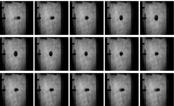
On the other hand, we show in Figure 6 the impact sequences obtained by the lateral camera for the test on thick plate specimen (ref. 08-134). The impact side of the plate is initially painted in white to optimize the projectile observation. The pictures show that the projectile is highly deformed at the impact, before an elastic return during the rebound.
Table 1. Test parameters of the two examples.
Specimen reference 08-139 08-134
Specimen thickness thin thick
HP chamber inflate pressure (bar) 8 38
Projectile initial velocity V0(m/s) 114.2 157.9
Projectile rebound velocity Vr(m/s) 29.8 35.2
Er E0¼ 100 V2 r V2 0 (%) 10.3 5.7
Figure 6. Ref. 08-134 specimen, thick plate, lateral camera (SA1), resolution 768r768 pixels, video sequence
Figure 7 shows the strain-gage signals recorded during the impacts. For a considerate gage on the two targets, its level is almost the same. Then, for the two selected examples, difference of thickness is compensated by the difference of incidental energy of the projectile. For other tests, the gage levels are in accordance with the initial velocity V0. The maximum strain is observed on the central gages J9A and J9C, just on the impact centre. The signal is positive, result of a tensile loading on the opposite side caused by the global flexion of the plate. To note, a short passage in compression at the first moments, caused probably by the stress wave reflection. Then, the gages situated on the diameter 100 mm respond before those placed on the diameter 200 mm. This observation is in agreement with the propagation time of the strain in the target material. The synchronization between the gage signals on the same diameter can be justified by a non-centred impact.
4. CONCLUSION
In this paper we presented new experimental set-up allowing the investigation of the rubber projectile impact on laminate composites panels. For each test, we can obtain velocity before and after impact, the strain at twelve positions and two high-speed videos. While the experimental set-up allows impact angles from 20 to 90x, only the normal impact (90x) was considered here. Further experiments are necessary to exploit the set-up at best.
Acknowledgments
AIRBUS is highly acknowledged for the financial support of this research.
References
[1] Zhao H., Abdennadher S., Othman R., Int. J. Impact Eng. 32 (2006) 1174–1189.
[2] Gue´gan P., Lebreton D., Pasco F., Othman R., Le Corre S., Poitou A., Proc. Inst. Mech. Eng. Part D. J. Automobile Eng.222 (2008) 699-704.
[3] Mines R.A.W., McKown S., Birch R.S., Int. J. Impact Eng. 34 (2007) 627-646. [4] Karagiozova D., Mines R.A.W., Int. J. Impact Eng. 34 (2007) 647-667.
[5] Othman R., Bussac M.N., Collet P., Gary G., Comptes Rendus Acade´mie des Sciences Se´rie IIb329 (2001) 369-376.
[6] Bussac M.N., Collet P., Gary G., Othman R., J. Mech. Phys. Solids 50 (2002) 321-349. [7] Othman R., Gary G., Exper. Mech. 47 (2007) 295–299.
[8] Othman R., Gue´gan P., Challita G., Pasco F., Lebreton D., Int. J. Impact Eng. 36 (2009) 460–467.
[9] Aloui S., Othman R., Poitou A., Gue´gan P., El-Borgi S., Mech. Res. Comm. 35 (2008) 392–397.