HAL Id: hal-01007281
https://hal.archives-ouvertes.fr/hal-01007281
Submitted on 19 Nov 2017
HAL is a multi-disciplinary open access
archive for the deposit and dissemination of
sci-entific research documents, whether they are
pub-lished or not. The documents may come from
teaching and research institutions in France or
abroad, or from public or private research centers.
L’archive ouverte pluridisciplinaire HAL, est
destinée au dépôt et à la diffusion de documents
scientifiques de niveau recherche, publiés ou non,
émanant des établissements d’enseignement et de
recherche français ou étrangers, des laboratoires
publics ou privés.
Sensitivity of the flow stress of Nylon 6 and Nylon 66 to
strain-rate
Issam Ben Naceur, Ramzi Othman, Pierrick Guégan, Abderrazek Dhieb,
Fakhreddine Dammek
To cite this version:
Issam Ben Naceur, Ramzi Othman, Pierrick Guégan, Abderrazek Dhieb, Fakhreddine Dammek.
Sen-sitivity of the flow stress of Nylon 6 and Nylon 66 to strain-rate. International Journal of Modern
Physics B, World Scientific Publishing, 2008, 22 (9-11), pp.1249-1254. �10.1142/S021797920804661X�.
�hal-01007281�
SENSITIVITY OF THE FLOW STRESS OF NYLON 6 AND NYLON 66 TO STRAIN-RATE
ISSAM BENACEUR
Unite de Mecanique, Modelisation et Productique (U2MP), Ecole Nationale d'Jngenieur de Sfax, BP. W 3038 Sfax Tzmisie.
RAMZI OTHMAN* and PIERRICK GUEGAN
Institut de Recherche en Genie Civil et Mecanique (GeM), Ecole Centrale de Nantes I rue de la Noe, BP 92101, 44321 Nantes cedex 3, France.
*rarnzi.othrnan@ ec-nantes.fr
ABDERRAZEK DHIEB and FAKHREDDINE DAMEK
Unite de Mecanique, Modelisation et Productique (U2MP), Ecole Nationale d'Ingenieur de Sfax, BP. W 3038 Sfax Tzmisie.
The sensitivity of the flow stress of polymers to strain-rate is one of the major concerns in mechanics of materials since polymers and polymer matrix composites are widely used in many engineering applications. In this paper, we present tests on Nylon 6 and Nylon 66 on wide range of strain-rates (0.001-5000s-1
). Specifically, we used INSTRON machine for low strain-rates. The high strain-rate
measurements were inferred from the Hopkinson bar tests. Only the compressive behaviour was investigated. To eliminate any interference with temperature and humidity effects, test samples were conditioned at 20°C and 50% of hygrometry. Moreover, the effects of the specimen geometry were considered. The current study results are also compared to values found in literature.
Keywords: Hopkinson bar; Nylon 6; Nylon 66; strain rate; flow stress.
1. Introduction
Polymeric materials and their composites became very useful in many industries because of their low production cost, low density, corrosion resistance, good load bearing capacity, etc. Among other fields, polymers are used in aerospace and automobile engineering. For these applications, they are subjected to high rate loadings. Therefore, it is of a major importance to identify the constitutive equations and, consequently to measure the mechanical properties of these materials, at a wide range of strain rates.
The behaviour of polymers fell into three different groups1:
(1) a linear relationship between the flow stress and the logarithm of the strain rate; (2) a bilinear relationship with an increase in the gradient at a strain rates higher than 103s 1; and
(3) a decrease of the maximum flow stress at about 103s-1, eventually followed by an
increase.
The linear behaviour is in line with the Eyring model,2 whereas, the bilinear behaviour was observed in Chou et al.,3 to cite one among others. Briscoe and Nosker4 examined the influence of friction and the specimen geometry and concluded that the bilinear behaviour is non physical and is only due to measurement problems. Recently, many works5-7 showed that the bilinear materials can be attributed to some physical
properties of polymers.
Among thermoplastic polymers, Nylons are widely used materials. In this paper, we investigate the influence of the strain rate on the flow stress of Nylon 66 and Nylon 6. To check the influence of the specimen geometry, two geometries are considered for Nylon 66 and four for Nylon 6. Samples are conditioned at 20°C and 50% of hygrometry for at least one week to eliminate any interference between strain rate effects and temperature or hygrometry effects.
2. Experimental set-up 2.1. Hopkinson bar apparatus
The conventional configuration of the Hopkinson bar technique8 consists of two elastic bars (Fig. 1). One gauge station is cemented on each bar. A compressive wave is generated by the impact of a striker on the input bar. This incident wave moves through the input bar till the bar-specimen interface. At this interface, a first part of the wave is reflected back into the input bar as a tensile wave and a second part is transmitted through the specimen into the output bar as a compressive wave (the transmitted wave). The input gauge station measures the incident and reflected waves and the output gauge records the transmitted waves. The input gauge is cemented in the middle of the input bar and the striker length is taken less than twice the input bar length. In this case, the incident and the reflected waves are recorded separately with the input gauge. Assuming one-dimensional wave propagation in the bars, the force applied by the bars on the specimen and the velocity of the two specimen-bar interfaces are given by:
F';n
(t)
=
A;,1Eb1knc
(t)
+Ere}(t ))
V;n
(t)
=
-Cin knc
(t)-
Ere{(t))
(la) (2a) Fout(t)
= AoutEoutEtra(t)
vout(t)
= -cou/E/ra(t)
(lb) (2b)where the subscripts ;m out' inn ref and 1ra mean input bar, output bar, incident wave,
reflected wave and transmitted wave, respectively, and A is the cross-section area, E the Young's modulus, <: is the wave's strain, c the wave velocity. Assuming a dynamic equilibrium in specimen, the stress, the strain-rate and the strain in the specimen are recovered as follows:
a(t)
=F';n (t
)+
Fout(t)
2As (3a) • ( )~!Ill
(t)-
vin
(t)
£ t = ---"'"--'--'---"'---'--'-ls (3b)I
c-(t)=
fe(r)dr
0where,
A,
the cross-section area of the sample andl,
its length.Striker I I I I I Input bar I I I I I Digital storage oscilloscope
Fig. I. Simplified Scheme of the Hopkinson bar apparatus.
0o~~,,~~~~~~w~~w~~~~~~~1CO Strain(%) Output bar I I I I I Strain(%) (3c) Hydraulic damping system \
Fig. 2a. Selected stress-strain curves for PA6
(D,=lOmm).
Fig. 2b. Selected stress-strain curves for P A66 (l, = 3 mm). 150 fi ~40 tl..13(J a; -170 >R ;: no ra1oo
"'
"'
90"
~ 00 0 ~ iO u:: 60Strain rate (s-1) Strain rate (s-1)
2.2. Experimental results
Two polymers are considered in this study: Nylon 6 and Nylon 66. The specimens' length is equal to 6 mm for Nylon 6 and the diameter is varied from 8 to 14 mm. The length to diameter ratio is compared in Tab.1 a to the optimal length to diameter ratio which reduces inertia effects9. This optimal ratio is equal to:
( _1_J
=
.fj
V (4)lD.,
opt 2where V is the Poisson ratio of the polymer (this parameter will be taken equal to 0.4 for both of polymers).
The Nylon 66 specimens have a fixed diameter which is equal to 10 mm whereas two lengths values are considered: 3 and 6 mm. The length to diameter ratio is compared to the optimal ratio in Tab.l b.
Specimen Geometry I 2 3 4 Specimen Geometry I 4
l,
(mm) 6 6 6 6l,
(mm) 3 6D,
(mm) 8 10 12 14D,
(mm) 10 10(
~'
)/(
~'
lpl
2.16 1.73 1.44 1.23(~J/(~Jopt
0.86 1.73Table I a. Geometry of Nylon 6 Specimens Table lb. Geometry of Nylon 66 SpeCimens
Strain rate (s-1) Strain rate (s-1)
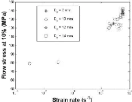
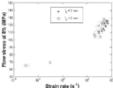
Fig. 3c. Flow stress of PA6 at 15% of strain. Fig. 4a. Flow stress of P A66 at 8% of strain.
m' 102 1DD 1Cl4
Strain rate (s"1) Strain rate (s"1
)
~ 11.
e
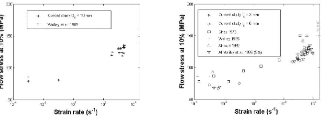
'$.,150 0 Strain rate (s-1)Fig. Sa. Flow stress of P A6.
Strain rate (s'1)
Fig. 5b. Flow stress of P A66.
In this study, tests at low strain rates are carried out on an INSTRON machine. At high rate of loading, a steel Hopkinson bar is used (Fig. 1 ). The bars are 16mm in diameter. The Young's modulus is 190GPa. The elastic limit is 1400MPa. The strain measurements are recorded at a frequency rate of lOMHz than filtered numerically using low-pass filter at a cutting frequency equal to 100kHz. The stress, strain and strain-rate are recovered from the measured signals using the software DA VID10 developed at the Ecole Polytechnique (France). In Figs. 2, some selected stress-strain curves at different strain rates are presented. In Figs. 3, we show the flow stress of Nylon 6 as function of the logarithm of the strain rate at 8 (Fig. 2a), 10 (Fig. 2b) and 15% (Fig. 2c) of strain. Curves show clearly a bilinear behaviour which is independent of the sample geometry. The geometry has an effect of some MPas which is of same order of magnitude as measurement errors. The gradients are independent of the geometry parameters. Neverthless, they depend on the level of the strain. For the first linear part, the gradient is important for low strains. However, for the second part the gradient is higher for the important strains. The same results are obtained on Nylon 66 (see Figs. 4).
In Figs. 5, we compare the current study results to values found in literature.3•5-6•11-12 The
same tendency is observed for strain rates lower than 5000/s. The variation of the flow stress as a function of logarithm is bilinear. However, two behaviours are found at strain rates higer than 5000/s. AI-Maliky et al.6 found a drop in the flow stress contrarily to Walley et al. 11 This drop in flow stress is also observed in Walley et al. 5 The current study does not show any decrease in the stress-strain rate curve. In fact, we do not go further than a strain rate of 5000/s.
3. Conclusion
In this study, we investigated the behaviour of Nylon 6 and Nylon 66 in a wide range of strain rate (0.001-5000/s). The samples were condition at 20oc and 50% of hygrometry to eliminate the interference of the influence of the strain and the influence of temperature or hygrometry. We studied also the influence of length to diameter ratio. We found that geometry effects are of some MPas. The variation of the flow stress of Nylon 6 and Nylon 66 as function of logarithm of the strain rate fell into the bilinear behaviour which is in line with values found in literature.
Acknowledgment
The authors want to thank Franc Pasco for his help in the experimental work.
References
I. C.R. Siviour, S.M. Walley, W.G. Proud, J.E. Field, Polymer 46, 12546 (2005). 2. H. Eyring, J. Chem. Phy. 4, 283 (1936).
3. S.C. Chou, K.D. Robertson, J.H. Rainey, Exper. Mech. 13,422 (1973). 4. B.J. Briscoe, R.W. NOSKER, Polym. Comm. 26,307 (1985).
5. S.M. Walley, J.E. Field, P.H. Pope, N.A. Safford, Philos. Trans. Roy. Soc. London A 328, I (1989).
6. N. Al-Maliky, J.O. Fernandez, D.J. Parry, G.M. Swallowe, J. Mater. Sci. Letters 17, 1141 (1998).
7. S. Hamdan, G.M. Swallowe, J. Mater. Sci. 31, 1415 (1996). 8. H. Kolsky, Proceedings Phys. Soc. B 62, 676 (1949).
9. E.D.H. Davies, S.C. Hunter, J. Mech. Phy. Solids 11, 155 (1963). 10. G. Gary, V. DeGreff, DAVID User Manual.
11. S.M. Walley, J.E. Field, G.M. Swallowe, S.N. Mentha, J. Phyisque Colloque C5 46, 607 (1985).