HAL Id: hal-01168182
https://hal.archives-ouvertes.fr/hal-01168182
Submitted on 25 Jun 2015
HAL is a multi-disciplinary open access
archive for the deposit and dissemination of
sci-entific research documents, whether they are
pub-lished or not. The documents may come from
teaching and research institutions in France or
abroad, or from public or private research centers.
L’archive ouverte pluridisciplinaire HAL, est
destinée au dépôt et à la diffusion de documents
scientifiques de niveau recherche, publiés ou non,
émanant des établissements d’enseignement et de
recherche français ou étrangers, des laboratoires
publics ou privés.
Feasibility of luminescent multilayer sol-gel thermal
barrier coating manufacturing for future applications in
through-thickness temperature gradient sensing
Etienne Copin, Thierry Sentenac, Yannick Le Maoult, Fabien Blas, Florence
Ansart, Vanessa Vidal, Philippe Lours
To cite this version:
Etienne Copin, Thierry Sentenac, Yannick Le Maoult, Fabien Blas, Florence Ansart, et al.. Feasibility
of luminescent multilayer sol-gel thermal barrier coating manufacturing for future applications in
through-thickness temperature gradient sensing. Surface and Coatings Technology, Elsevier, 2014,
vol. 260, pp. 90-96. �10.1016/j.surfcoat.2014.08.077�. �hal-01168182�
To cite this version : Copin, Etienne and Sentenac, Thierry and Le
Maoult, Yannick and Blas, Fabien and Ansart, Florence and Vidal,
Vanessa and Lours, Philippe Feasibility of luminescent multilayer
sol-gel thermal barrier coating manufacturing for future applications in
through-thickness temperature gradient sensing. (2014) Surface and
Coatings Technology, vol. 260. pp. 90-96. ISSN 0257-8972
To link to this article : doi:
10.1016/j.surfcoat.2014.08.077
URL :
http://dx.doi.org/10.1016/j.surfcoat.2014.08.077
O
pen
A
rchive
T
OULOUSE
A
rchive
O
uverte (
OATAO
)
OATAO is an open access repository that collects the work of Toulouse researchers and
makes it freely available over the web where possible.
This is an author-deposited version published in :
http://oatao.univ-toulouse.fr/
Eprints ID : 14032
Any correspondance concerning this service should be sent to the repository
administrator:
staff-oatao@listes-diff.inp-toulouse.fr
Feasibility of luminescent multilayer sol-gel thermal barrier coating
manufacturing for future applications in through-thickness temperature
gradient sensing
Étienne Copin
a,⁎
, Thierry Sentenac
a, Yannick Le Maoult
a, Fabien Blas
a,b, Florence Ansart
b,
Vanessa Vidal
a, Philippe Lours
aaUniversity of Toulouse, Mines Albi
–Institut Clément Ader, Campus Jarlard, F-81013 Albi Cedex 09, France
bUniversity of Toulouse, UPS-INP-CNRS, Institut Carnot CIRIMAT, 118 Route de Narbonne,31062, Toulouse, Cedex 09, France
a b s t r a c t
Keywords:
Thermal barrier coating Sol-gel
Luminescence Phosphor Sensor
This paper investigates the feasibility of manufacturing sol-gel multilayer thermal barrier coatings (TBC) func-tionalized with different lanthanide ions Ln3+having distinct photo-luminescence emission wavelengths
(Ln = Sm, Eu, Dy, Er, Tm) for future applications in temperature gradient sensing. Ln3+doped 9.75 mol% yttria
stabilized zirconia (YSZ) powders were produced to study the effect of activator concentration on luminescence intensity and host matrix crystal structure. Self-quenching was found to limit the maximum signal-to-noise ratio achievable with Sm3+, Dy3+, Er3+and Tm3+activators, which was not the case for Eu3+in the 1–10 mol% range.
The increase in activator was found to affect the crystal structure of YSZ. A solution was proposed that suppressed this effect while significantly increasing the luminescence intensity of all activators. Finally a TBC sensor proto-type integrating Eu3+, Er3+and Dy3+doped layers distributed throughout the thickness was successfully
depos-ited by a dip-coating sol-gel process and showed promising through-thickness luminescence sensing capabilities.
1. Introduction
The progressive use and improvement of thermal barrier coatings (TBCs) to protect critical components from heat damage in gas turbines have allowed significant increase in turbine inlet temperature over the last 30 years[1,2]. Today's jet engines' efficiency and durability there-fore greatly depend on TBC's reliability and performance. The degrada-tion during service of the current standard 6–8 wt% yttria stabilized zirconia (YSZ) based TBCs is mainly caused by the initiation and the propagation of microcracks at the interface between either the bond coat and the thermally grown oxide (TGO) or the TGO and the ceramic overcoat resulting from the thermal expansion coefficient mismatch be-tween coatings and substrates[3,4]. This sub-surface mode of failure makes an early detection particularly difficult. The development of reli-able predictive models for YSZ overcoat spallation is indeed limited by the difficulty of accessing the effective interface temperature that governs this process through conventional means without compromis-ing the integrity of the coatcompromis-ing. This results in strongly conservative margins being imposed to allow safe operation of jet engine turbine components.
From this perspective there has been a growing interest in the appli-cation of phosphor thermometry methods for the diagnostic of TBCs as
the partial transparency of YSZ in the visible range of the spectrum allows to collect local information conveyed by the luminescence emis-sions from optically excited luminescent layers integrated throughout the depth of the TBC[5,6]. This functionalization can be obtained by the introduction of optically active components such as trivalent lantha-nide ions directly into the crystal structure of YSZ, thus without any detrimental alterations of the coating properties[6–8]. Such “sensor TBCs” has shown high potential for measuring substrate/TBC interface temperature[9,10]or investigate local interface delamination[11,12]
by non intrusive optical sensing.
Reported here is a feasibility study for the design and manufacturing of multilayer functionalized TBCs, deposited by a dip-coating process from sol-gel precursors, alternative to the standard electron beam phys-ical vapor deposition (EB-PVD) and atmospheric plasma spraying (APS) methods used for YSZ coatings, for future applications in through thick-ness measuring of temperature gradients. This cost effective process allows one to deposit 9.75 mol% porous YSZ TBCs presenting the meta-stable t’ phase with performance under cyclic oxidation comparable to that of EB-PVD coatings[13,14]. The easy composition control offered by the technique has already generated interest for manufacturing some high purity YSZ:Er and YSZ:Sm phosphor coatings and powders
[15]. Therefore the effect of additions of several dopants including Sm, Eu, Dy, Er and Tm in 9,75 mol% YSZ was investigated, and a solution is proposed for the optimization of YSZ luminescence properties. A proto-type of multilayer TBC with three luminescent layers with distinct
⁎ Corresponding author. Tel.: +33 5 63 49 32 82. E-mail address:etienne.copin@mines-albi.fr(É. Copin).
luminescence emissions embedded throughout the thickness, respec-tively doped with Eu, Er and Dy, was deposited by dip-coating and characterized to assess the feasibility of the process.
2. Thermal barrier coating sensors
The health monitoring issues brought by the critical role played by TBCs in the durability of jet engines led to the development of the concept of multifunction TBCs, that combine thermal insulating and op-tical sensing capabilities. The latter are based on the semi-transparency of zirconia in the visible range and its ability to accept small amounts of trivalent lanthanide ions that substitute for Zr4+cations in its lattice
and act like luminescent activators under appropriate UV or visible illumination (Fig. 1), thus providing information about their local environment. First introduced by Amano et al[16]in 1988, multilayer TBCs alternating various luminescent and undoped layers allow one to evaluate the progression of TBC erosion from the appearance/ extinction of luminescent peaks or directly from evolutions of intensity maps[17,18]. Eldridge et al.[11,12]later showed that the effect of re-flectance enhanced luminescence, which creates an intensity contrast between metal/YSZ:Eu and air/YSZ:Eu interfaces, can reveal localized delaminated areas at the interface region in APS-TBCs integrating a 7– 10 μm luminescent sublayer. Finally the application of phosphor thermometry methods[19,20], mainly based on the dependence of luminescence intensity and decay time on temperature, allows non-intrusive optical sensing of buried luminescent layers to determine through-thickness temperature. Application to bilayer systems such as YSZ:Dy/YSZ[9,21]and YSZ:Eu/YSZ[10]has thus allowed measure-ments of substrate/YSZ interface temperature. The existence of several dopants with distinct luminescence emission peaks suggests that more complex layered TBC architectures, also referred by Gentleman and al.[6]as “rainbow sensors”, could be powerful tools to measure the complete temperature gradient or heat flux across TBCs.Fig. 1 pre-sents the luminescence spectra of the various luminescent activators in 9.75-YSZ selected for this work on the basis of their luminescence properties and performance as thermographic phosphors either in YSZ or other matrices. Several doublets and triplets of compatible activators such as Tm-Er-Eu or Dy-Er-Eu are thus indentified as valid candidates to build multiwavelength TBCs sensors for through thick-ness health and temperature monitoring. It should be born in mind that although Dy3+and Tm3+appear to have distinct emissions,
thermalization of the4I
15/2level of Dy3+at high temperature will
generate an additional peak at 458 nm potentially overlapping the peaks of Tm3+[22], limiting to three the number of functionalized
luminescent layers that could be used for this range of activators. Of all dopants presented inFig. 1, Eu3+, Er3+and Dy3+exhibit the
brightest luminescence in YSZ in addition to having distinct emission peaks in the red, green and blue region of the visible spectrum respec-tively, that therefore make them the best candidates for the design and the manufacturing of a multilayer TBC sensor prototype.
3. Experimentation 3.1. Synthesis of YSZ phosphors
YSZ phosphor powders (9.75 mol% YO1.5) with contents of LnO1.5
(Ln = Eu, Er, Dy, Sm or Tm) between 0.15 and 10 at% were synthesized using the sol-gel route[23]. The sols were prepared by mixing zirconi-um (IV) propoxide (Zr(OPr)4) (Sigma Aldrich) and appropriate con-tents of yttrium (III) and Ln (III) nitrates (Sigma Aldrich) as precursors in a solution of 1-propanol (Sigma Aldrich) and ultrapure water. Acetylacetone (AcAc) (Sigma Aldrich) was used as a complexing agent to control the kinetics of hydrolysis of the zirconium alkoxide[24]. The volume rates of [AcAc/Zr(OPr)4] and [H2O/Zr(OPr)4] were kept
con-stant at 0.8 and 9.5 respectively. More details about the preparation of the mixtures from the reagents can be found in reference[23]. After 30 min of mechanical stirring the solutions were then held for one night (~16 h) at 50 °C to accelerate the hydrolysis and condensation of the sols into bright monolith gels free of precipitates. The solvent was then evaporated in a drying oven at 70 °C. The resulting dried gels, called xerogels, were subsequently calcined for 2 h at 800 °C to remove the remaining traces of solvents and then manually ground to powders for 4 min. The products obtained at this stage are white pow-ders consisting in 2–50 μm particles of partially crystallized YSZ. An additional heat treatment of the powders at 1100 °C for 2 h ensured the full crystallization of the YSZ into metastable quadratic phase t’ or cubic phase c depending on their composition.
3.2. Deposition of TBC sensors
Multilayer TBC sensor prototypes containing luminescent layers of composition Ln’
xY0.0975-xZr1-0.092-xO1.951-2x(Ln’= Eu, Er or Dy) with
distinct emissions wavelengths were shaped by a dip-coating process previously developed[14,15].
First YSZ aerogel powders were synthesized from a sol-gel protocol adapted from Lecompte et al.[25]. Rare earth doped YSZ gels were pre-pared as described in part 3.1 but were dried above the supercritical point of 1-propanol (Tc= 261 °C; Pc= 5.1 MPa) in a stainless steel
au-toclave (Paar Instrument 4621) instead of being dried in free air. Tem-perature was kept constant at 270 °C and pressure at 9 MPa for 1 h, afterwards the solvent was slowly released in isothermal conditions. The resulting brittle monolithic aerogels whose structure is similar to that of the wet gels were calcined for 2 h at 700 °C and ball milled at 250 rpm for 1 h in an agate mortar to obtain highly porous powders having morphological and grain size characteristics more suitable for dispersion and deposition by dip-coating than xerogel powders obtain-ed through conventional drying at atmospheric pressure[23,26].
The substrates used for the depositions were AM1 single crystal nickel based superalloy coupons coated with Ni(Pt,Al) bondcoat, previ-ously sand blasted with 10 μm corindon particles and preoxidized for 2 h at 950 °C under a O2pressure of 0.05 Pa. Slurries were prepared
by mixing 20 wt% of YSZ sol with YSZ aerogel powder previously dis-persed in 1-propanol with polyvinylpyrrolidone 3500 (PVP) (Acros Or-ganics) dispersing agent. The depositions were carried out at room temperature by dipping the substrates in the slurry with a controlled withdrawal rate of 250 mm/min to ensure the deposition of a ~10– 15 μm thick layer at each dip procedure. The deposited films were then dried for 5 min at 50 °C before implementing the next dip-coating. Coatings of final thickness in the range of 100–150 microns were obtained after 13 successive dips. Multilayer prototypes alternating
Fig. 1. Luminescence spectra in the visible range for various lanthanide-doped 9.75 mol%-YSZ:Ln phosphors (Ln = Sm, Eu, Dy, Er and Tm) under long wave UV illumina-tion from a mercury vapor lamp (365 nm). The content of Sm3+, Dy3+, Er3+and Tm3+
luminescent and unmodified YSZ layers such as shown inFig. 2were built by successive dipping into slurries with different compositions. Subsequently, samples were sintered for 2 h at 1100 °C. The heating and cooling rates were set at 50 °C/h to minimize thermal stresses caused by the mismatch between the thermal expansion coefficients of the coating and the substrate.
3.3. Characterization
The luminescence spectra of both powders and coatings were re-corded at room temperature over the 400–700 nm range with an Ocean Optics USB2000 spectrometer equipped with a 1000 μm optical fiber. A Philips TL 6 W BLB mercury vapor lamp (main UV emission peak at 365 nm) and a 1.1 W continuous wave diode pumped solid state green laser operating at 532 nm (CNI laser) were used as excita-tion sources of the phosphors. A color CCD camera (AVT PIKE F-145C) was used to record images of the luminescence intensity emitted by the embedded luminescent sublayers. A narrow band interference filter centered at 636 nm (FWHM ~10 nm) was also used to filter the lumi-nescence signal from the YSZ:Eu3+layer.
Structural analysis of YSZ powders and coatings were performed by X-rays diffraction (XRD) measurements. XRD patterns were collected by scanning the angular range from 25° to 100° with a PANalytical X’Pert diffractometer equipped with a X’Celerator linear detector using Cu Kα(λ(CuKα1) = 1.5406 Å; λ(CuKα2) = 1.5445 Å) as the
X-ray source. The operating voltage and currents were respectively 45 kV and 40 mA, with a step size of 0.08° 2θ and a step time of 0.25 s. The determination of crystal parameters was performed by Rietveld re-finement[27,28]of the DRX patterns with the commercial software PANalytical X’Pert HighScore Plus using the P42/mcn and Fm3m space
groups for the quadratic and cubic phases respectively. Scanning elec-tron microscope (SEM) observations of the powders and coatings cross sections were achieved using a FEI Nova Nanosem 450 field emis-sion gun scanning electron microscope (FEG-SEM) operating at an accelerating voltage of 10 kV. The position and thickness of the different layers were determined from energy-dispersive X-ray (EDX) measure-ments performed on multilayer coating cross sections with the same SEM.
4. Results and discussion
4.1. Effects of luminescent activators concentration
The significant reduction of the luminescence intensity combined with the increasing interferences caused by thermal radiations at tem-peratures above 1000 °C are critical issues limiting signal-to-noise ratio in high temperature luminescence thermometry[20,29,30]. It is therefore of utmost concern to choose judicious activator concentration
ranges so that the selected phosphors show strong luminescence, although the range of concentrations for which the lifetime decay ex-hibits appropriate variations with temperature may warrant the use of a different strategy. Increased non-radiative interactions between acti-vators can indeed cause shortening of the lifetime or lead to decay times with complex waveform that can make the processing of the data for luminescence lifetime analysis more difficult[7,19]. The intro-duction of activator species within the host lattice must also remain non intrusive to avoid detrimental effects on the desired primary prop-erties of the host material. In order to study the effect of activator concentration on luminescence performance and crystal structure, 9.75-YSZ-type phosphors xerogel powders with various contents of SmO1.5, Eu O1.5, Dy O1.5, Er O1.5and Tm O1.5were synthesized. The
xerogel route was chosen for convenience as the process is more suit-able for the production of a large quantity of small batches. Although there are some differences in terms of particles morphology and distribution with aerogel powders used for TBC deposition, the relative effect of activator composition on luminescence and crystal structure is expected to remain the same[23].
4.1.1. Effects on luminescence intensity
Fig. 1gives a representative example of the luminescence spectra from the different phosphors under continuous long-wave UV illumina-tion of a mercury vapor lamp (365 nm). As the concentraillumina-tion in trivalent lanthanide ion activators was modified the only change ob-served in the luminescence spectra, not shown here, was the evolution of the intensities of the main luminescence peaks. This evolution is plotted inFig. 3. The intensities of the main peaks were normalized by the corresponding maximum intensity in each spectrum. 9.75-YSZ phosphors doped with Dy, Sm, Er and Tm all exhibit an optimum of the intensity of the luminescence peaks for concentrations between 1 and 1.63 at%, after which further increases in activator content lead to lower intensities as a result of an increase of radiationless energy trans-fers between close neighboring dopant ions, a process also referred to as concentration quenching or self-quenching. The plotted lines inFig. 3
represent the fit of the experimental data points with the direct excita-tion, self-quenching model by Johnson-Williams[31,32]relating the luminescence efficiency η of the activator (assumed to be proportional to the observed relative intensity) and the activator concentration C by the expression η ¼ C 1−Cð Þ Z C þσ σ0ð1−CÞ : ð1Þ
Z and σ/σ’ are two fitting parameters, the former standing for the number of lattice positions (intersticial or substitutional) in the vicinity of an activator ion such that if another activator occupies one of these positions no luminescence will occur, and the latter standing for the ratio of the capture cross sections of photons by the host lattice and the activators.
The values obtained typically between 17–30 and 0.003–0.007 for Z and σ/σ’ respectively are consistent with reported values in the litera-ture for YSZ:Ln type phosphors[6]. Luminescence output of these phos-phors can thus be optimized with relatively limited composition modifications of the host material. The spectra given as an example in
Fig. 1provide a comparison of the luminescence strength of the differ-ent dopants Sm3+, Dy3+, Er3+and Tm3+at their optimal concentration
in 9.75 at% YSZ mentioned above. Interestingly one can notice that Er3+
appears to emit a significantly brighter intensity than Dy3+, Sm3+and
Tm3+respectively in that particular host matrix.
It can be noticed inFig. 3.d that conversely to the other activators no self-quenching of luminescence is observed for YSZ:Eu in the 1–10 at% range, for which the luminescence intensity of the spectral lines is observed to linearly increase by one order of magnitude in that range. This behavior can be explained by the difference in self-quenching
properties between Eu3+ions and the other dopants investigated.
While the presence of intermediary states between the initial excited state and the ground state in the energy level distribution of Er3+,
Sm3+, Dy3+and Tm3+favors self-quenching at relatively low
concen-trations by cross relaxation, the large gap in energy between the top5D 0
emitting level from which the 591 nm and 606 nm are originated (~17 250 cm−1) and the top of the7F
6-0ground multiplet (~5000 cm−1) of
Eu3+electronic structure makes concentration quenching by this
mul-tipolar transfer process considerably less probable[7,33–35]. The self-quenching of Eu3+rather occurs by non-resonant transfer interactions
strongly dependent upon crystal structure[33]and is not expected to occur in a YSZ matrix at concentrations below 10 at%[36]. Therefore in-tensity emissions up to more than 4 times that of other activators can be achieved with a 10 mol% addition of Eu3+. Since Eu3+can also stabilize
the desirable metastable tetragonal phase t’ of ZrO2in the same way as
Y3+does[37–39]it potentially offers more flexibility for the design of
strongly emitting YSZ phosphors, although it might be limited by the potential effect of high concentration on luminescence, known to lead to quicker and more complex luminescence lifetime decays[7,19]. This latter aspect is still currently under investigation for the range of phosphors presented here.
4.1.2. Effects on YSZ crystal structure
The crystal structure of the various phosphor powders doped with Sm3+, Eu3+, Dy3+, Er3+and Tm3+was investigated by X-Ray
diffrac-tion (XRD).Fig. 4.a shows the three diffraction patterns of both un-doped and Er3+doped 9.75-YSZ xerogel powders in the [30°–100°] 2θ
range. The diffraction peaks observed on the un-doped YSZ pattern and the calculated c/a√ 2 of 1.0096 correspond to the metastable t’ crys-tal structure expected for YSZ with this composition prepared by this sol-gel route[23,40]. The diffraction patterns of powders doped with
Fig. 3. Evolution of the intensities of the main luminescence peaks normalized by the corresponding maximum intensity for each spectrum with the concentration of a) DyO1.5, b) Sm O1.5,
c)Er O1.5, d) Eu O1.5and Tm O1.5in 9.7at% YSZ xerogel powders. Plotted lines correspond to the fit of the experimental data points with the Johnson-Williams model[31,32](Eq.(1)).
Fig. 4. Diffraction patterns for 9.7 mol% YSZ:Er powders with increasing content of Er O1.5
1.47 and 3 mol% confirm that they also crystallize in the t’ structure. However some changes are noticeable for some of the high angle peaks. In particular it can be observed inFig. 4.b that the angular dis-tance between the (004)t’and (220)t’reflections of the t’ phase initially at 73.2° and 74.3° tends to decrease with increasing Er content. These two peaks end up almost totally convolved for 3 mol% of Er3+. The
same observation is made for the doublets of peaks at 35, 60° and 84° 2θ angles. These results indicate that the material tends towards a cubic structure[40,41], a tendency also observed for similar concentra-tions in the Sm, Eu, Dy and Tm doped YSZ powders.
The evolution of the c/a√ 2 values calculated from the refinement of the spectra by the Rietveld method reported inFig. 5is consistent with these observations. For all dopants the c/a√ 2 ratio decreases linearly from the initial value of 1.0096 to nearly one in the range 0.5–6 mol%, as the quadratic phase progressively turns into the undesirable cubic phase. Finally, a single cubic phase is obtained for powders with Eu3+
content above 6 mol%, and the trends observed inFig. 5suggest that a single cubic phase would be obtained with similar contents of Sm3+,
Dy3+, Er3+or Tm3+. This linear decrease of the c/a√ 2 ratio from 1.01
to 1 is typically reported in the literature for ZrO2doped with more
than 10 mol% of YO1.5, the minimum amount to ensure complete
stabi-lization of the cubic phase being around 15 to 16 mol%[23,40]. These values are close to the corresponding 15.75 at% overall dopant concen-tration (YO1.5+ EuO1.5) required to fully stabilize the cubic phase in the
9.75-YSZ:Eu3+phosphor powders presented here. Therefore it is
con-cluded that the significant impact on the tetragonality of the quadratic phase at the relatively low concentrations required for optimizing lumi-nescence intensity (1–1.63 mol%) is rather an effect of the overall sub-stitution of Zr4+by trivalent ions having larger ionic radius than an
effect of the specific nature of the dopants. The functionalization of 9.75-YSZ without significant alteration of the sought crystal structure for TBC applications is thus limited by the already high content of YO1.5necessary to stabilize the desirable metastable tetragonal phase
t’. This is particularly limiting for YSZ:Eu3+that was shown to exhibit
large increases in luminescence intensity in the range of 1–10 mol%, for which compromises appear to be necessary for a good balance be-tween luminescent and structural properties.
4.2. Optimization of YSZ phosphors
In order to minimize the impact of rare earth additions in YSZ crystal structure, it was proposed to keep constant the overall dopant content in the lattice, i.e. to partially substitute the Y3+stabilizing ions by
lumi-nescent markers. This solution was motivated by the fact that a mini-mum of 8 mol% YO1.5only is necessary for the synthesis of quadratic
zirconia by the sol-gel route used in this work[40]and by the t’-ZrO2
stabilizing ability—reported by various authors[37–39,42,43]—of some
of these elements such as Eu3+or Dy3+. The XRD patterns in the 2 θ
range 70–90° of 9.75-YSZ and 7.75-YSZ powders containing 2 mol% Eu3+are compared to that of un-doped YSZ inFig. 6. As seen previously
in part 4.1.2, additions of 2 mol% of Eu to 9.75-YSZ cause a significant distortion of the unit cell, illustrated inFig. 6by the convolution of the (004)t’and (220)t’diffraction peaks at 74° as well as the low value of the calculated c/a√2 ratio (1.0055). This effect is suppressed by the substitution of 2 mol% of Y3+by the same amount of Eu3+, that thus
preserves a t’ phase presenting a c/a√2 ratio (1.0105) very close to that of the non-functionalized material (1.0102). Furthermore, further increasing the substitution rate to 4 mol% also appears to have very little additional effects on the crystal structure, suggesting the suitability of this solution for the fabrication of high luminescence efficiency YSZ:Eu phosphors. The crystal lattice parameters calculated for all the YSZ:Ln aerogel phosphor powders investigated are displayed inTable 1, and the comparison with that of un-doped 9.75YSZ powder confirms the relevance of Y3+partial substitution for minimizing the impact of
activator introduction on the microstructure (c/a√2 ratios close to 1.01). Finally the luminescence spectra presented inFig. 7illustrate a quite interesting side effect of Y3+substitution by Ln3+. Indeed
low-ering the Y3+content by 2 mol% generates a 53% increase of the
maximum peak intensity of the5D
0→7F1(591 nm) and5D0→7F2
(606 nm) transitions in YSZ:Eu 2 mol% aerogel powders. This effect appears to be dependent on Y3+concentration as observations on
5.75-YSZ:Eu 4 mol% showed that the intensity corresponding to the above mentioned transitions increased by more than 60%. It was also observed that the emissions of all the other activators investigated (Table 1) are also enhanced by 8 to 30%, depending on the nature of the activator and the luminescence peak. At this stage it is still unclear whether this effect is related to the quenching of the luminescence by the Y3+ions (or the associated oxygen vacancies), or is the result of
changes in the optical properties of the host material in the emitting/ excitation range of the rare earth activators (transmission, absorption). 4.3. Characterization of a multilayer TBC sensor prototype
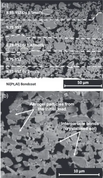
To investigate the feasibility of multilayer TBC sensor manufacturing from sol-gel precursors, 100 to 150 μm thick prototypes containing three thin luminescent layers with distinct emissions wavelengths (re-spectively doped with Eu3+, Er3+an Dy3+) distributed throughout the
thickness were deposited on nickel superalloy coupons by dip-coating (Fig. 2). After sintering at 950 °C for 2 hours, smooth and uniform white coatings were obtained. XRD analysis confirmed that they all pos-sess the desired metastable quadratic t’ structure with a c/a√2 ratio of 1.0104.Fig. 8shows SEM cross-section micrographs of a representative 100 μm prototype. The coating presents the typical microstructure of a sol-gel TBC consisting of a highly porous network of aerogel particles is-sued from the initial slurry bonded together by the crystallized sol (Fig. 8.b). The isotropic nature of the resulting porosity is believed to
Fig. 5. Evolution of the tetragonality coefficient c/a√2 with LnO1.5content (Ln = Sm, Eu,
Dy, Er or Tm) in ZrO2already containing 9.75 mol% of YO1.5.
Fig. 6. XRD patterns of various YSZ:Eu powders illustrating the effect of partial substitution of YO1.5by EuO1.5on YSZ crystal structure.
provide a good balance between thermal insulation and thermo-mechanical strength[13,14,44].
The position and thickness of the different layers determined by EDX analysis are indicated inFig. 8.a. There were no signs of adherence loss or crack initiation and propagation at interfaces between layers or between the substrate and the deposit, indicating the satisfactory sintering of the coating as a morphologically uniform single layer well adherent to the substrate. The main concern regarding the design of TBC sensor is the individual thickness and thickness uniformity of the luminescent layers. Since TBCs are subject to large thermal gradients, uniform sensing layer thicknesses of about 10 μm of below are to be pre-ferred to avoid significant errors in the temperature readings[20]. There are in general little thickness variations within each layers, although the presence of some large particles (dimensions N15–30 μm) can locally disturb the layers' uniformity and density, either because of their large dimension or by contributing to the creation of large pores. However it should be noticed that the upper layers present a significantly larger thickness than the lower ones for the same deposition conditions, as the increase of the viscosity of the sol with time results in some notice-able film thickening with increasing number of dips. Nevertheless this effect can be easily controlled by adapting the number of dips for each layer or the withdrawal speed.
Fig. 9presents the luminescence spectra of a coating under continu-ous UV illumination. The peaks corresponding to the YSZ:Dy top layer are clearly visible at 584–590 nm and 480–496 nm. However, the two doublets of peaks corresponding to the luminescent transitions in Er3+at 516–524 nm and 544–561 nm are barely distinguished from
the background, and no luminescence peaks from the YSZ:Eu layer are observed. Indeed the low power UV illumination source, that emits in a low transmission range of YSZ (365 nm)[5,6], does not provide enough energy to the deepest layers to either excite the activators or generate a sufficiently strong luminescence output from the coating.
Fig. 10shows a filtered image of the TBC prototype under the illumina-tion of a continuous high power laser operating at 532 nm, a wave-length that allows to stimulate both Er3+and Eu3+luminescence[6].
Although the5D
0→7F3transition of Eu3+at 636 nm, on which is
centered the narrowband filter used, is 4 times less bright than the
5D
0→7F2emission line at 606 nm, the luminescence of the YSZ:Eu3+
layer at the interface with the bond coat is clearly visible. These results confirm the successful deposition of a TBC with luminescence sensing properties throughout the whole thickness.
Table 1
Crystal lattice parameters of various YSZ:Ln aerogel powders (Ln = Sm, Eu, Dy, Er or Tm) determined by the Rietveld method from XRD spectra.
Material a and b (Å) c (Å) c/a√2 9.75-YSZ 3.6137 5.1625 1.0102 8.12-YSZ:Sm 1.63 mol% 3.6153 5.1656 1.0103 7.75-YSZ:Eu 2 mol% 3.6154 5.1664 1.0105 8.25-YSZ:Dy 1.5 mol% 3.6134 5.1640 1.0106 8.28-YSZ:Er 1.47 mol% 3.6135 5.1623 1.0102 8.25-YSZ:Tm 1.5 mol% 3.6133 5.1617 1.0101
Fig. 7. Luminescence spectra of YSZ:Eu powders illustrating the increase of luminescence intensity with partial substitution of YO1.5by EuO1.5in YSZ:Eu phosphors.
Fig. 8. a) SEM micrograph of a Eu-Er-Dy functionalized multilayer TBC sensor prototype cross section and b) details showing aerogel particles and interparticle bonding.
Fig. 9. Luminescence spectra of a Eu-Er-Dy functionalized multilayer TBC sensor prototype under continuous UV illumination (365 nm).
5. Conclusion
Over the last decade non-contact phosphor thermometry methods applied to standard TBC systems have shown their relevance for accessing the temperature of a luminescent sub-surface YSZ layer func-tionalized with Eu3+and Dy3+activators[9,10]. 9.75-YSZ:Ln (Ln = Sm,
Eu, Dy, Er, Tm) phosphor powders have been successfully synthesized by the sol-gel route, and the influence of activator concentration on luminescence intensity and crystal properties was studied. The lumi-nescence of Sm3+, Dy3+, Er3+and Tm3+is quenched due to energy
in-teractions between activator ions for contents around 1–1.5 mol%, limiting the maximum intensity achievable to that optimum. On the other hand the luminescence intensity of Eu3+ions increases linearly
by an order of magnitude in the 1–10 mol% range, exceeding significant-ly that of other activators at high content (up to 4 times at 10 mol%). However high overall content of Zr4+substitution with Y3+and Ln3+
that have larger ionic radius on cationic sites, initially of 9.75 mol%, was found to have a strong impact on the host crystal structure, promot-ing the transition from the tetragonal metastable t’ phase toward the undesirable cubic phase. This effect could be suppressed by substituting part of the Y3+with Ln3+luminescent activators to maintain the overall
dopant substitution rate at 9.75 mol%, which stabilizes the quadratic t’ phase with a c/a√2 ratio of 1.01. Furthermore this partial substitution goes along with a significant increase of the observed luminescence transition intensities, up to 50% in the case of YSZ:Eu 2 mol%. Y3+partial
substitution therefore provides an effective solution for optimizing YSZ: Ln phosphors luminescence intensity via non-intrusive composition modifications, especially in the case of Eu3+for which bright intensity
can be achieved at high doping contents. Of all dopants investigated, Eu3+, Er3+and Dy3+exhibit the brightest luminescence in YSZ and
present distinct emission peaks in the red, green and blue regions of the visible spectrum respectively that make them compatible for manufacturing multi-wavelength TBC sensors for in-depth sensing. 100–150 thick multilayer TBC architectures integrating three Eu, Er and Dy doped thin layers distributed throughout the thickness were thus successfully deposited on Ni(Pt, Al) coated AM1 substrates by dip-coating in a slurry of phosphor powders in sol-gel precursors. Preliminary observations of their microsctructural and luminescence properties confirm the potential of this architecture as a TBC optical sensor for luminescence sensing across the thickness. These results are promising for future investigation of their through-thickness
temperature and thermal gradients sensing capabilities with non-contact phosphor thermometry methods.
Acknowledgements
The authors would like to thank Guillaume Pujol for his kind assis-tance with the materials synthesis and the deposition of the coatings. Thanks to the École des Mines d’Albi and the Carnot CIRIMAT Institute for their material and financial contribution to this work.
References
[1]S. Bose, High Temp. Coat, Butterworth-Heinemann, Burlington, 2007, pp. 155–232.
[2]D.S. Rickerby, Design with engineering materials and coatings system for advanced aeroengine applications, Rolls Royce Plc, Derby, UK, 2012.
[3]N.S. Cheruvu, K.S. Chan, R. Viswanathan, Energy Mater. Mater. Sci. Eng. Energy Syst. 1 (2006) 33–47.
[4]H.E. Evans, Surf. Coat. Technol. 206 (2011) 1512–1521.
[5] J.I. Eldridge, T.J. Bencic, S.W. Allison, D.L. Beshears, J. Therm. Spray Technol. 13 (2004) 44–50.
[6]M.M. Gentleman, D.R. Clarke, Surf. Coat. Technol. 188 (2004) 93–100.
[7]M.D. Chambers, D.R. Clarke, Annu. Rev. Mater. Res, Annual Reviews, Palo Alto, 2009, pp. 325–359.
[8]A.L. Heyes, J. Lumin. 129 (2009) 2004–2009.
[9] J.R. Nicholls, R.G. Wellman, R. Steenbakker, J. Feist, Adv. Sci. Technol. 72 (2010) 65–74.
[10] M.M. Gentleman, J.I. Eldridge, D.M. Zhu, K.S. Murphy, D.R. Clarke, Surf. Coat. Technol. 201 (2006) 3937–3941.
[11] J.I. Eldridge, T.J. Bencic, Surf. Coat. Technol. 201 (2006) 3926–3930.
[12] J.I. Eldridge, T.J. Bencic, C.M. Spuckler, J. Singh, D.E. Wolfe, J. Am. Ceram. Soc. 89 (2006) 3246–3251.
[13] L. Pin, F. Ansart, J.-P. Bonino, Y. Le Maoult, V. Vidal, P. Lours, J. Eur. Ceram. Soc. 33 (2013) 269–276.
[14] L. Pin, V. Vidal, F. Blas, F. Ansart, S. Duluard, J.-P. Bonino, et al., J. Eur. Ceram. Soc. 34 (2014) 961–974.
[15] L. Pin, C. Pilgrim, J. Feist, Y. Le Maoult, F. Ansart, P. P. Lours, Characterisation of thermal barrier sensor coatings synthesised by sol-gel route, Sens. Actuators Phys. (2014).
[16] K. Amano, H. Takeda, T. Suzuki, M. Tamatani, M. Itoh, Y. Takahashi, Thermal barrier coating, US4774150 (A), 1988.
[17] J.I. Eldridge, J. Singh, D.E. Wolfe, J. Am. Ceram. Soc. 89 (2006) 3252–3254.
[18] C.C. Pilgrim, S. Berthier, J.P. Feist, R.G. Wellman, A.L. Heyes, Surf. Coat. Technol. 209 (2012) 44–51.
[19] S.W. Allison, G.T. Gillies, Rev. Sci. Instrum. 68 (1997) 2615–2650.
[20] J. Bruebach, C. Pflitsch, A. Dreizler, B. Atakan, Prog. Energy Combust. Sci. 39 (2013) 37–60.
[21] J.P. Feist, P.Y. Sollazzo, S. Berthier, B. Charnley, J. Wells, J. Eng. Gas Turbines Power-Trans. Asme 135 (2013).
[22] A.L. Heyes, S. Seefeldt, J.P. Feist, Opt. Laser Technol. 38 (2006) 257–265.
[23] J. Fenech, C. Viazzi, J.-P. Bonino, F. Ansart, A. Barnabé, Ceram. Int. 35 (2009) 3427–3433.
[24] M. Shane, M.L. Mecartney, J. Mater. Sci. 25 (1990) 1537–1544.
[25] A. Lecomte, F. Blanchard, A. Dauger, M.C. Silva, R. Guinebretière, J. Non-Cryst. Solids 225 (1998) 120–124.
[26] J. Fenech, Nouvelles compositions de revêtements de zircone substituée (Y, La, Sm, Er) élaborées par la voie sol-gel: applications aux barrières multicouches, Manu-script de thèse Université de Toulouse, 2010.
[27] H.M. Rietveld, J. Appl. Crystallogr. 2 (1969) 65–71.
[28] L.B. McCusker, R.B. Von Dreele, D.E. Cox, D. Louër, P. Scardi, J. Appl. Crystallogr. 32 (1999) 36–50.
[29] A.H. Khalid, K. Kontis, H.-Z. Behtash, Proc. Inst. Mech. Eng. Part G J. Aerosp. Eng. 224 (2010) 745–755.
[30] A.H. Khalid, K. Kontis, Luminescence 26 (2011) 640–649.
[31] P.D. Johnson, F.E. Williams, J. Chem. Phys. 18 (2004) 323–326.
[32] P.D. Johnson, F.E. Williams, J. Chem. Phys. 18 (2004) 1477–1483.
[33] L.G.V. Uitert, L.F. Johnson, J. Chem. Phys. 44 (2004) 3514–3522.
[34] L.G.V. Uitert, J. Electrochem. Soc. 107 (1960) 803–806.
[35] D.L. Dexter, J.H. Schulman, J. Chem. Phys. 22 (2004) 1063–1070.
[36] M.M. Gentleman, High temperature sensing of thermal barrier materials by lumi-nescence, ProQuest, 2006.
[37] L. Chen, Y. Liu, Y. Li, J. Alloys Compd. 381 (2004) 266–271.
[38] S. Dhiren Meetei, S. Dorendrajit Singh, N. Shanta Singh, V. Sudarsan, R.S.
Ningthoujam, M. Tyagi, et al., J. Lumin. 132 (2012) 537–544.
[39] J. Liao, D. Zhou, B. Yang, R. Liu, Q. Zhang, Opt. Mater. 35 (2012) 274–279.
[40] C. Viazzi, J.-P. Bonino, F. Ansart, A. Barnabé, J. Alloys Compd. 452 (2008) 377–383.
[41] S.A. Tsipas, J. Eur. Ceram. Soc. 30 (2010) 61–72.
[42] J. Fenech, M. Dalbin, A. Barnabe, J.P. Bonino, F. Ansart, Powder Technol. 208 (2011) 480–487.
[43] K. Smits, L. Grigorjeva, D. Millers, A. Sarakovskis, A. Opalinska, J.D. Fidelus, et al., Opt. Mater. 32 (2010) 827–831.
[44] J. Sniezewski, Y. LeMaoult, P. Lours, L. Pin, V.M. Bekale, D. Monceau, et al., Surf. Coat. Technol. 205 (2010) 1256–1261.
Fig. 10. Images of a multilayer TBC prototype (a) under white light illumination, (b) illuminated with a 532 nm laser showing the luminescence intensity at 636 nm from the YSZ:Eu3+layer located at the interface with the bond coat.