HAL Id: hal-01757387
https://hal.archives-ouvertes.fr/hal-01757387
Submitted on 6 Aug 2018
HAL is a multi-disciplinary open access
archive for the deposit and dissemination of sci-entific research documents, whether they are pub-lished or not. The documents may come from teaching and research institutions in France or abroad, or from public or private research centers.
L’archive ouverte pluridisciplinaire HAL, est destinée au dépôt et à la diffusion de documents scientifiques de niveau recherche, publiés ou non, émanant des établissements d’enseignement et de recherche français ou étrangers, des laboratoires publics ou privés.
Biosourced polymer foam production using a (SC CO2)
-assisted extrusion process
Audrey Common, Élisabeth Rodier, Martial Sauceau, Jacques Fages
To cite this version:
Audrey Common, Élisabeth Rodier, Martial Sauceau, Jacques Fages. Biosourced polymer foam pro-duction using a (SC CO2) -assisted extrusion process. 12th European Meeting on Supercritical Fluids, ISASF, May 2010, Graz, Austria. 13 p. �hal-01757387�
Biosourced polymer foam production using a (SC
CO2)-assisted extrusion process
Audrey COMMON*, Elisabeth RODIER, Martial SAUCEAU, Jacques FAGES
Université de Toulouse, Centre RAPSODEE, FRE CNRS 3213, École des Mines d'Albi, F-81013 Albi, France
[email protected]; fax : 00 33 5 63 49 30 25
A process based on extrusion coupled with supercritical carbon dioxide (scCO2) was
implemented. scCO2 modifies the rheological properties of the material in the barrel of the
extruder and acts as a blowing agent during the relaxation at the passage through the die. An experimental device based on a single-screw extruder allows the injection of scCO2 into the
melt, the mixing of both components and the creation of porosity into the extruded polymer. In this work, it was used to produce foams of two bio sourced, semi-crystalline polymers The effects on material porosity of different parameters such as, temperature before and after the die, pressure drop or CO2 concentration, were studied. Different configurations on the
extruder were tested. INTRODUCTION
Polymers are widely used in several areas. However, due to their slow degradation and the predicted exhaustion of the world petroleum reserves, significant environmental problems have arisen. Therefore, it is necessary to replace them with biosourced polymers with equivalent properties. It is also important to find new way to process them, which are more environmental friendly.
Extrusion is a process converting a raw material into a product of uniform shape and density by forcing it through a die under controlled conditions [1]. It has extensively been applied in the plastic and rubber industries, where it is the most important manufacturing process. A particular application concerns the generation of polymeric foams. Polymeric foams are expanded materials with large applications in the packaging, insulating, pharmaceutical and car industries because of their high strength/weight ratio or their controlled release properties. Conventional foams are produced using either chemical or physical blowing agents. Various chemical blowing agents, which are generally low molecular weight organic compounds, are mixed with a polymer matrix and decompose when heated beyond a threshold temperature. This results in the release of a gas, and thus the nucleation of bubbles. This implies however the presence of residues in the porous material and the need for an additional stage to eliminate them.
Injection of scCO2 in extrusion process modifies the rheological properties of the polymer in
the barrel of the extruder and scCO2 acts as a blowing agent during the relaxation when
extrusion and scCO2 would allow the use of fragile or thermolabile molecules, like
pharmaceutical molecules. The absence of residues in the final material is also an advantage for a pharmaceutical application.
Our lab has developed a scCO2-assisted extrusion process that leads to the manufacturing of
microcellular polymeric foams and already elaborated microcellular foams using a biocompatible amorphous polymer [3, 4]. In this work, this process has been applied to two semi-crystalline biosourced polymers. Foam production of semi-crystalline polymer is less frequent in the literature. Crystallinity hinders the solubility and diffusion of CO2 into the
polymer and leads consequently to less uniform porous structure [5]. Moreover, it has been shown that a large volume expansion ratio could be achieved by freezing the extrudate surface of the polymer melt at a reasonably low temperature [6].
Thus, in this work, we investigate the feasibility of this process with biosourced semi-crystalline polymers. We first try to control and improve the porous structure, studying the influence of melt and die temperatures on PHBV, which a copolymer of poly3-hydroxybutyrate and hydroxyvalerate. Then, we modify the experimental device in order to experiment the mixing of carbon dioxide into the polymer. We used a different polymer for this study, called BP here, and we looked at the influence of the mixing device and of the carbon dioxide content.
MATERIALS AND METHODS
PHBV (Mw=600 kDa), with a HV content of 13 % and plasticized with 10 % of a copolyester
was purchased from Biomer (Germany). Melting onset temperature was measured at 159°C by DSC (ATG DSC 111, Setaram) and no glass transition temperature was detected at temperatures as low as –20°C. The solid density
€
ρP, determined by helium pycnometry
(Micromeretics, AccuPYC 1330) was found to be 1216 kg.m-3.
Melting onset temperature of the BP polymer was measured at 184°C by DSC (ATG DSC 111, Setaram) and the glass transition temperature was detected at 44°C. The solid density
€
ρP, determined by helium pycnometry (Micromeretics, AccuPYC 1330) was found to be
1027± 5 kg.m-3.
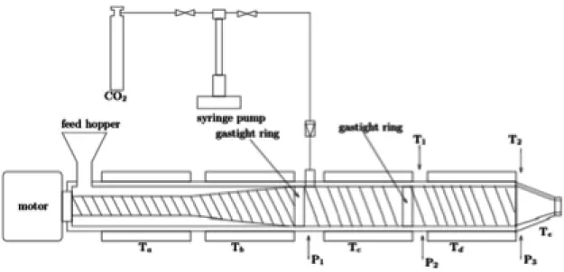
Figure 1 shows the experimental set up, which has previously been detailed elsewhere [3, 4]. The single-screw extruder has a 30 mm-screw diameter and a length to diameter ratio (L/D) of 35 (Rheoscam, SCAMEX). A great L/D ratio generally indicates a good capacity of mixing and melting but important energy consumption. The screw is divided into three parts. The first one has a length to diameter ratio of 20 and the two others have a length to diameter ratio of 7.5. Between each part, a restriction ring has been fitted out in order to obtain a dynamic gastight which prevents scCO2 from backflowing. The first conical part allows the transport
of solid polymers and then, their melting and plasticizing. Then, the screw has a cylindrical geometry from the first gastight ring to the die. This die has a diameter of 1 mm and a length of 11.5 mm. The temperature inside the barrel is regulated at five locations: Ta and Tb before
the CO2 injection, Tc and Td after the injection and Te in the die.
There are three pressure and two temperature sensors: P1 after the CO2 injector, P2 and T1
temperature and the pressure of the polymer inside the extruder. Errors associated to pressure and temperature measurements were about 2 bars and 3.3°C respectively.
CO2 (N45, Air liquide) is pumped from a cylinder by a syringe pump (260D, ISCO) and then
introduced at constant volumetric flow rate. The pressure in the CO2 pump is kept slightly
higher than the pressure P1. The CO2 injector is positioned at a length to diameter ratio of 20
from the feed hopper. It corresponds to the beginning of the metering zone, that is to say the part where the channel depth is constant and equal to 1.5 mm. The pressure, the temperature and the volumetric CO2 flow rate are measured within the syringe pump. CO2 density,
obtained on NIST website by Span and Wagner equation of state [7], is used to calculate mass flow rate and thus the CO2 mass fraction
€
wCO
2.
Figure 1: Experimental device
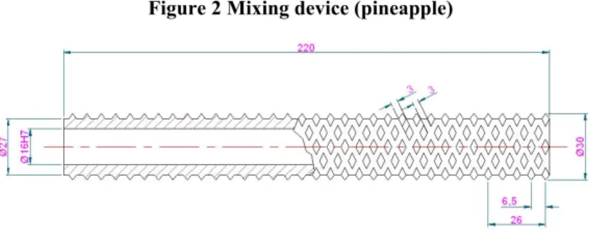
In the second part of the work, this device was modified, replacing the last part of the screw (7.5 L/D) by a mixing element, that is a pineapple mixer with diamond-shaped pins. This one can be seen on Figure 2.
Dynamic mixers are often used to improve mixing in single screw extruder. Distributive mixing and dispersing one are commonly distinguished even if they are not physically separated. The component to be mixed here is CO2 and the first mixing to ensure is the
distributive one. Hence, the aim here is to go further in this aspect. We chose a distributive mixer, like the pineapple one, which distributes spatially the phase to be mixed acting on the shear flow. The pineapple has advantages in that the flow turns to be streamlined, the barrel is well wiped by the pins and rather frequent flow splitting occurs [8].
The other type of mixers, the dispersive ones, generate high enough shear to allow breaking agglomerates. There are rather used to disperse a solid phase into a polymer melt.
Figure 2 Mixing device (pineapple)
Experimental conditions have to ensure that the polymer flows through the barrel without being thermally degraded. Temperatures have been adapted to each polymer to obtain rapid enough solidification after the die to avoid coalescence of the bubbles and a collapse of the foam structure but also to avoid the blocking of the screw.
As for PHBV, influence of the die temperature was tested. For each experiment, only the temperature of the metering zone Td and of the die Te were changed. The three other
temperatures Ta, Tb and Tc were kept constant at 160°C. CO2 mass fraction
€
wCO
2 was also kept
constant at 1.3 %, which might be less than solubility: in [9], for a similar polymer with a HV content of 12%, at 313K and 15 MPa, the solubility of CO2 was found to be of 55% in weight.
The rotation speed of the screw was fixed at 30 rpm. Three series of experiments were carried out. Td was fixed at 140°C, 135°C and 130°C respectively and Te varied from 140 down to
110°C. At lower values of Te, the extruder stopped due to over-limited pressure P3 according
to the established alarm value.
Then we tested the distributive mixing level in the metering zone using another biosourced polymer (BP). The introduction of a mixing element was tested in order to know its influence on the mixing efficiency. In each configuration, CO2 flowrate was varied and we studied its
influence on the porosity of the foams.
Once steady state conditions were reached, extrudates were collected and flowrates were measured. Several samples were collected during the experiment in order to check the homogeneous structure of the extrudates. To calculate the apparent porosity
€
ρapp, samples
were weighed and their volumes were evaluated by a water pycnometer. Porosity, defined as the ratio of the pore volume to total volume is calculated by equation 1:
€
ε = 1−ρapp
ρP (1)
€
ρP is the polymer density and
€
ρapp the apparent density of the extrudates.
The theoretical maximum porosity
€
εmax is obtained considering that all the dissolved CO2
becomes gaseous inside the extrudate at ambient conditions and thus create porosity. It is then calculated by the following equation:
€
εmax = wCO2ρP
wCO2ρP+ρCO2(atm) (2)
€
wCO
2 is the CO2 mass fraction and
€
Samples were also analysed with an helium pycnometer (Micrometerics AccuPyc 1330). Helium can reach open pores, so the density measurements allow to evaluate the closed porosity with the same equation 1.
To complete the characterization of the porosity structure, samples were examined by scanning electron microscopy (ESEM, FEG, Philips).
RESULTS
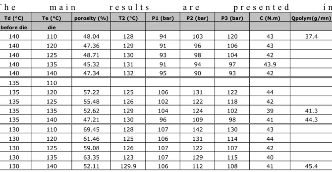
Results obtained with PHBV when testing the die and melt temperatures.
T h e m a i n r e s u l t s a r e p r e s e n t e d i n
Td (°C) Te (°C) porosity (%) T2 (°C) P1 (bar) P2 (bar) P3 (bar) C (N.m) Qpolym(g/mn) before die die
140 110 48.04 128 94 103 120 43 37.4 140 120 47.36 129 91 96 106 43 140 125 48.71 130 93 98 104 42 140 135 45.32 131 91 94 97 43.9 140 140 47.34 132 95 90 93 42 135 110 135 120 57.22 125 106 131 122 44 135 125 55.48 126 102 122 118 42 135 135 52.62 129 104 124 102 39 41.3 135 140 47.21 130 96 109 98 41 44.3 130 110 69.45 128 107 142 130 43 130 120 61.46 125 106 131 114 44 130 125 59.08 126 107 122 107 42 130 135 63.35 123 107 129 115 40 130 140 52.11 129.9 106 112 108 41 45.4
. The varying operating conditions are given, which are temperature Te in the die and Td
before the die, together with the resulting pressure evolution, torque, temperature T2 measured
before the die, and polymer flowrate measured at the die outlet. Rotation speed of the screw is fixed together with CO2 concentration.
Td (°C) Te (°C) porosity (%) T2 (°C) P1 (bar) P2 (bar) P3 (bar) C (N.m) Qpolym(g/mn) before die die
140 110 48.04 128 94 103 120 43 37.4 140 120 47.36 129 91 96 106 43 140 125 48.71 130 93 98 104 42 140 135 45.32 131 91 94 97 43.9 140 140 47.34 132 95 90 93 42 135 110 135 120 57.22 125 106 131 122 44 135 125 55.48 126 102 122 118 42 135 135 52.62 129 104 124 102 39 41.3 135 140 47.21 130 96 109 98 41 44.3 130 110 69.45 128 107 142 130 43 130 120 61.46 125 106 131 114 44 130 125 59.08 126 107 122 107 42 130 135 63.35 123 107 129 115 40 130 140 52.11 129.9 106 112 108 41 45.4
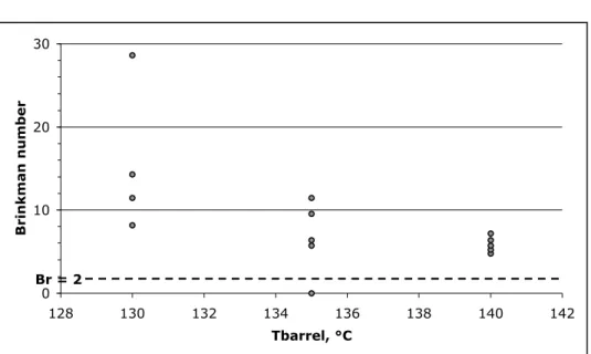
In order to investigate the temperature profiles, the Brinkman number, Br, was evaluated: it compares the extent of viscous heat generation relative to the heat conduction resulting from the imposed temperature difference (TBarrel-Tproduct), Tproduct being the temperature of the
product measured before the die, that is T2. It is calculated according to
€
Br = η vB
2
λP TB− Tp (3)
where vB is the relative velocity of the barrel, η the molten polymer viscosity, λP, the molten
polymer conductivity. A rheological study, which was previously investigated using a rheometer MARS, Thermo Scientific, showed a pseudo plastic behaviour and the viscosity was taken to be 1630 Pa.s for an average shear rate of 31 s-1 in the pumping zone. λ
P of the
solid polymer was measured at 150°C and found to be 0.205 W/m/K. The temperature difference was given by |Td-T2|. The values of Br are presented on
0 10 20 30 128 130 132 134 136 138 140 142 Tbarrel, °C Brinkman number Br = 2 in function of temperature of the barrel Td in the pumping zone. Brinkman number is found to be larger than
2, which means that there is a maximum temperature, over the barrel one, at a position interm ediate between the barrel wall and the screw surface. Viscous dissipation is then important in our case.
Figure 3: Brinkman number in function of Td 0 10 20 30 128 130 132 134 136 138 140 142 Tbarrel, °C Brinkman number Br = 2
Considering the porous structure, porosity is presented in function of the die temperature Te at
fixed melt temperature Td on figure 4.
Figure 4: Porosity in function of the die temperature at fixed metering zone temperature (diamonds at Tbarrel=140°C, circles at Tbarrel=135°C, crosses at Tbarrel=130°C)
0,3 0,35 0,4 0,45 0,5 0,55 0,6 0,65 0,7 0,75 100 105 110 115 120 125 130 135 140 145 Die temperature, °C porosity 140 130 135 Tbefore the die, Td, °C
Considering temperature effects at fixed die temperature, porosity decreases when melt temperature increases. This last one influences the CO2 solubility, which decreases as melt
temperature increases. It was previously observed for polystyrene that, at a reasonably low temperature of polymer melt, there exists an optimal die temperature for which large volume expansion ratio are achieved by freezing the extrudate surface [6]. This effect is explained
torque limitation.
At fixed melt temperature and as die temperature increases, porosity decreases or even remains constant at melt temperature of 140°C. Note that the highest die temperatures correspond to the lowest pressures before die P3, which are around 100±7 bars. Indeed, when
depressurization range decreases, nucleation rate decreases [10]. These explanations could be satisfying considering the porosity as a global characteristic but they may be incomplete considering the pore size and number.
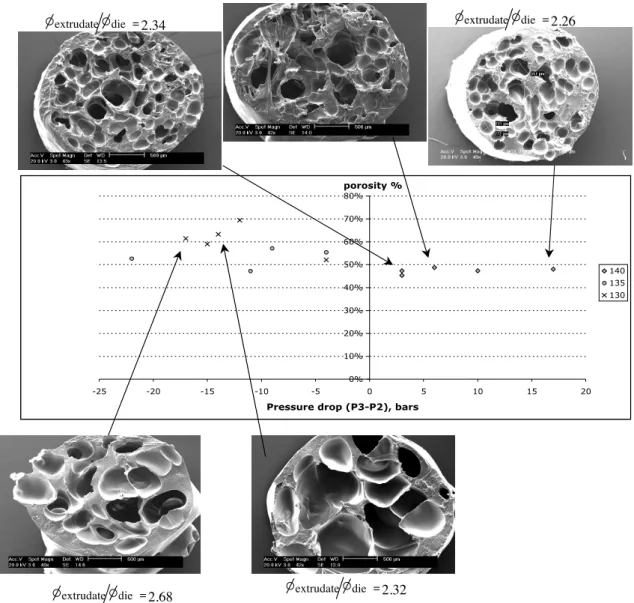
Going further into the pore structure analysis, it appears that the pore structure differs greatly according to the pressure drop through the metering zone, P3-P2, as it is shown on figure 5.
Figure 5: SEM pictures together with porosity results in function of pressure drop between P3 and P2.
0% 10% 20% 30% 40% 50% 60% 70% 80% -25 -20 -15 -10 -5 0 5 10 15 20
Pressure drop (P3-P2), bars porosity %
140 135 130
extrudate die =2.34 extrudate die =2.26
extrudate die =2.32
extrudate die =2.68
As P3 is greater than P2 and (P3-P2)ispositive,CO2 remains dissolved into the melt until the
flow reaches the die where nucleation occurs. This corresponds to the case when melt temperature is 140°C, which is then equal or higher than the die temperature. In addition, no significative effect of the die temperature is then observed. As P3 is lower than P2 and (P3-P2)
is negative, the mixture may desaturate, nucleation begin in the melt zone and then only growth take place in the die. This induces less pores but bigger ones, leading to a greater
porosity. This last one decreases with die temperature when transfer of CO2 out of the
extrudate is enhanced.
Endly, it can be noticed that, in any case, porosities measured remain below the maximal one, which was estimated at 90%.
Results obtained with BP when studying the influence of the distributive mixing and the CO2 concentration on porous structure.
Experiments investigating the influence of carbon dioxide content and the influence of the mixing device were performed. Table 2 presents the operating conditions of each experiment.
Table 2: Operating conditions in BP experiments
Experiment
number Mixingdevice Rotation Speed
Ta/b Tc/d Te T1 T2 P1 P2 P3
rpm °C °C °C °C °C bar bar bar
1 Classical
screw 40 220 180 175 174 174 65-85 65-85 50
2 Pineapple
mixer 40 240 180 180 183 176 50-70 110-140 60-70
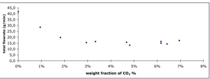
The first experiment was done with the former unmodified screw. We can see on Figure 6 that the total flowrate decreases with the increase of the CO2 content and then reaches a constant
value above 3% of CO2. This transition is also observed considering the structure aspect of
the foams. Below 3% of CO2, the pores are rather small near the surface of the extrudate and
are bigger in the center of the extrudate cross section. This can be explained by coalescence and growth enhanced by a slower cooling in the center than near the surface at the oulet of the die
Figure 6: Evolution of the total flowrate with the mass fraction of CO2
0,0 5,0 10,0 15,0 20,0 25,0 30,0 35,0 40,0 45,0 0% 1% 2% 3% 4% 5% 6% 7% 8% weight fraction of CO2 %
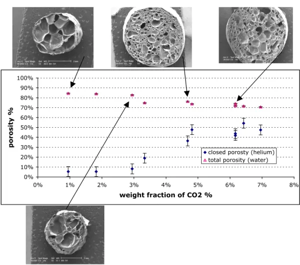
be closed. Those porosity measurements are in agreement with SEM observations. The increase of CO2 amount seems to increase the number of nucleation sites. In addition, the
increasing cooling effect of the depressurisation through the die freezes the structure as soon as the outlet of the die is reached or even before. The evolution of the porosity with carbon dioxide concentration is consistent with other reported works.
Figure 7 : Evolution of the porosity with CO2 fraction. Exp1.
0% 10% 20% 30% 40% 50% 60% 70% 80% 90% 100% 0% 1% 2% 3% 4% 5% 6% 7% 8%
weight fraction of CO2 %
porosity %
closed porosty (helium) total porosity (water)
Comparing to PHBV results, at low concentration of CO2, foams obtained look rather the
same. The negative pressure drop (P3-P2) might be the governing process leading to big pores. However, at high CO2 concentration, porosity levels remain rather high and the porous
structures seem to follow the classical statements from the literature: the governing mechanisms are those implied during the depressurization through the die and the cooling rate at the outlet of the die [10]. The negative pressure drop (P3-P2) through the metering zone doesn’t seem to influence anymore the porosity results: mass and heat transfer kinetics may be significantly different due to the big amount of carbon dioxide.
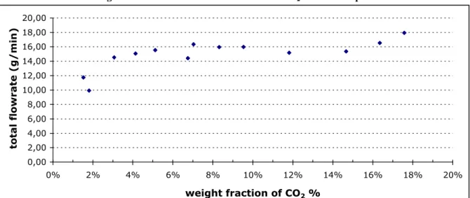
The second experiment was conducted using the pineapple mixing element. This device greatly changes the pressure profile in the extruder. It increases the pressure gradient from P2
to P3 enhancing the shear flow towards the die. It seems to improve the mixing since higher
contents of CO2 can be incorporated into the melt without noticing any failure while
processing the mixture. As we can see on Figure 8, the total flowrate is not disturbed by the addition of great amounts of carbon dioxide. Besides, the high porosity level is maintained until 15% of CO2. Above this amount, the total porosity is drastically decreased, as it is
shown on Figure 9 and the whole porosity is closed. There is far too much CO2 and the
induced freezing at the exit of the die prevents the pores from growing.
The pores obtained with the pineapple mixer are less homogeneous in size and are bigger than those obtained with the unmodified screw, at similar CO2 contents. This could be explained
by the pressure profile induced by the mixer compared to the unchanged screw. Pressure drop (P3-P2) is also negative but P2 is much higher, which may induce a significative desaturation
of the mixture. Hence, nucleation may take place in the metering zone of the extruder, as it is suspected for PHBV.
Figure 8: Evolution of total flowrate with CO2 fraction. Exp 2.
0,00 2,00 4,00 6,00 8,00 10,00 12,00 14,00 16,00 18,00 20,00 0% 2% 4% 6% 8% 10% 12% 14% 16% 18% 20% weight fraction of CO2 %
total flowrate (g/min)
Figure 9: Evolution of porosity with CO2 fraction. Exp2.
0% 10% 20% 30% 40% 50% 60% 70% 80% 90% 100% 0% 2% 4% 6% 8% 10% 12% 14% 16% 18% 20%
weight fraction of CO2 %
porosity %
closed porosity (helium) total porosity (water)
porous structure obtained is not homogeneous and pores remain rather large. Besides, the high pressure drop induced in the mixer element zone enhances the shear flow towards the die together with a desaturation of the mixture. It also increases the counterpressure flow before this mixing zone forcing some carbon dioxide towards the hopper, which could explain some CO2 leaks that we occasionally observed. Considering then the higher amounts of CO2 and
the raise in pressure P2 at the upstream part of the mixing device, not all the carbon dioxide
may be processed through the die. Therefore, if great amounts of CO2 are required in the
mixture depending on the process aim, possibly above the solubility value, an additional static mixer could be placed between the screw and the die. The CO2 introduction could then be
splitted between the actual one and another one placed just before the static mixer. This last one might improve again the mixing and allow incorporating carbon dioxide above the solubility value without flowing back through the hopper. Experiments are currently conducted to understand the impact of those mixing devices on the porosity and on the homogeneity of the extrudates.
CONCLUSION
PHBV foaming by extrusion assisted by supercritical fluid is thus feasible according to the temperature profile established. Porosity up to 70% was obtained. However, beyond the temperature profile effect, this foaming seems greatly influenced by the pressure profile, especially by the pressure drop through the metering zone just before the die. Shear flow may be enhanced together with desaturation of the mixture leading to early nucleation before the die. Comparing to the case when counterpressure flow is favoured and the mixture kept saturated, it leads to less pores but bigger ones and to a greater porosity. Acting on distributive mixing level by the introduction of a pineapple element and testing another biosourced polymer led to similar observations concerning the effect of the pressure profile. Foams with porosities up to 85% were obtained but the porous structure is not homogeneous and pores remain rather large. The high pressure drop induced in the mixer element zone enhances the shear flow towards the die together with a desaturation of the mixture. It also increases the counterpressure flow before this mixing zone forcing some carbon dioxide towards the hopper. Hence, this mixing element is not well adapted if dense and small pores are required. Endly, experiments with this biosourced polymer with the unmodified screw, so without the pineapple element, led to results consistent with literature ones. When saturation of the mixture is maintained all along the screw until the die is reached by maintaining a sufficient pressure level, the governing mechanisms are those induced by the depressurisation rate through the die and the cooling rate at the die outlet.
REFERENCES
[1] RAUWENDAAL C., Polymer Extrusion, Hanser Publishers, München, 2001.
[2] SAUCEAU M., PONOMAREV D., NIKITINE C., RODIER E., FAGES J., Improvement of extrusion processes using supercritical carbon dioxide, In: Supercritical Fluid and Materials, INPL, Vandoeuvre (France), 2007, 217
[3] NIKITINE C., RODIER E., SAUCEAU M., FAGES J., Residence time distribution of a pharmaceutical grade polymer/supercritical CO2 melt in a single screw extrusion process, Chem. Eng. Res. Design, in press [4] NIKITINE C., RODIER E., SAUCEAU M., LETOURNEAU J.-J., FAGES J., Controlling the structure of a porous polymer by coupling supercritical CO2 and single screw extrusion process, J. Appl. Polym. Sci., submitted
[5] DOROUDIANI S., PARK C.B., KORTSCHOT M.T., Processing and characterization of microcellular foamed high-density polyethylene/isotactic polypropylene blends, Polym. Eng. Sci., 38, 1998, 1205
[6] PARK C. B., BEHRAVESH A. H., VENTER R. D., Low density microcellular foam processing in extrusion using CO2, Polym. Eng. Sci. 38, 1998, 1812
[7] SPAN R., WAGNER W., A New Equation of State for Carbon Dioxide Covering the Fluid Region from the Triple-Point Temperature to 1100 K at Pressures up to 800 MPa, J. Phys. Chem. Ref. Data, 25, 1996, 6, 1509 [8] RAUWENDAAL C., Mixing in polymer processing, Marcel Dekker ed., New York, 1991
[9] CRAVO C., DUARTE A. R. C., DUARTE C. M. M., Solubility of carbon dioxide in a natural biodegradable polymer: determination of diffusion coefficients, J. Supercrit. Fluids, 40, 2007, 194
[10] HAN X., KOELLING K. W., TOMASKO D. L., LEE, L. J. , Effect of die temperature on the morphology of microcellular foams, Polym. Eng. Sci., 43, 2003,1206.