En vue de l'obtention du
DOCTORAT DE L'UNIVERSITÉ DE TOULOUSE
Délivré par :
Institut National Polytechnique de Toulouse (INP Toulouse)
Discipline ou spécialité :
Sûreté de Logiciel et Calcul à Haute Performance
Présentée et soutenue par :
M. FAIEZ ZALILA
le mardi 9 décembre 2014
Titre :
Unité de recherche :
Ecole doctorale :
METHODS AND TOOLS FOR THE INTEGRATION OF FORMAL
VERIFICATION IN DOMAIN-SPECIFIC LANGUAGES
Mathématiques, Informatique, Télécommunications de Toulouse (MITT)
Institut de Recherche en Informatique de Toulouse (I.R.I.T.)
Directeur(s) de Thèse :
M. YAMINE AIT AMEURM. XAVIER CREGUT
Rapporteurs :
M. HASSAN MOUNTASSIR, UNIVERSITE DE FRANCHE COMTE M. PIERRE-ETIENNE MOREAU, UNIVERSITE DE LORRAINE
Membre(s) du jury :
1 M. FRANÇOIS VERNADAT, INSA TOULOUSE, Président
2 M. BENOIT COMBEMALE, UNIVERSITE RENNES 1, Membre
2 M. MARC PANTEL, INP TOULOUSE, Membre
Remerciements
La réalisation d’une thèse est un travail qui nécessite beaucoup d’ambition, d’enthousiasme et de patience. En effet ce travail n’aurait jamais pu être réalisé sans le soutien d’un grand nombre de personnes.
Je tiens à remercier en premier lieu mes chers encadrants Marc Pantel et Xavier Crégut pour la confiance qu’ils m’ont accordée en acceptant d’encadrer mon stage de Master Recherche et ce travail doctoral.
J’étais vraiment chanceux d’être entouré par l’humanité, la gentillesse et la grande cul-ture générale et scientifique de Marc Pantel. Je le remercie infiniment pour sa compréhen-sion, son investissement et sa disponibilité de jour comme de nuit.
Un éternel merci à Xavier Crégut. Merci pour ta disponibilité, ton écoute, ta sympathie, tes conseils et la justesse de tes critiques qui ont guidé mes réflexions et qui ont fait de cette période une formation à la recherche très intéressante et l’objet d’un travail intense. Pour tout cela je vous suis infiniment redevable.
Merci à Yamine Ait-Ameur qui a accepté d’être mon directeur de thèse.
Je remercie Pierre-Etienne Moreau et Hassan Mountassir pour m’avoir fait l’honneur d’être rapporteurs de cette thèse. Je suis honoré pour l’intérêt qu’ils ont porté à ce travail.
Mes vifs remerciements à François Vernadat et Benoît Combemale qui ont bien accepté d’être examinateurs de cette thèse. Je leur exprime ma profonde reconnaissance d’être des membres du jury.
Je tiens à remercier tous les membres du laboratoire IRIT et l’ensemble du personnel de l’IRIT pour leur assistance administrative et logistique ainsi que pour leur sympathie et je pense particulièrement à nos chères secrétaires à Sylvie Eichen, Sylvie Armengaud-Metche et Audrey Cathala.
J’ai une pensée également pour tous les membres de l’équipe ACADIE et toutes les per-sonnes avec qui j’ai partagé mon bureau: Florent, Arnaud, et Ning.
Mes vifs remerciements vont également à tous les amis ceux qui sont en Tunisie et qui m’encouragent toujours, ou que j’ai connu ici en France.
Je dédie cette thèse à mes parents pour leur soutien et leur encouragement à ma sœur et son mari pour leurs conseils et aides et à ma fiancée pour avoir supporté mon stress.
Faiez Zalila
MÉTHODES ET OUTILS POUR L’INTÉGRATION DE LA VÉRIFICATION
FORMELLE POUR LES LANGAGES DÉDIÉSRésumé
Les langages dédiés de modélisation (DSMLs) sont de plus en plus utilisés dans les phases amonts du développement des systèmes complexes, en particulier pour les systèmes cri-tiques embarqués. L’objectif est de pouvoir raisonner très tôt dans le développement sur ces modèles et, notamment, de conduire des activités de vérification et validation (V&V). Une technique très utilisée est la vérification des modèles comportementaux par explo-ration exhaustive (model-checking) en utilisant une sémantique de traduction pour constru-ire un modèle formel à partir des modèles métiers pour réutiliser les outils performants disponibles pour les modèles formels. Définir cette sémantique de traduction, exprimer les propriétés formelles à vérifier et analyser les résultats nécessite une expertise dans les méth-odes formelles qui freine leur adoption et peut rebuter les concepteurs. Il est donc nécessaire de construire pour chaque DSML, une chaîne d’outils qui masque les aspects formels aux utilisateurs.
L’objectif de cette thèse est de faciliter le développement de telles chaînes de vérification. Notre contribution inclut 1) l’expression des propriétés comportementales au niveau métier en s’appuyant sur TOCL (Temporal Object Constraint Language), une extension temporelle du langage OCL; 2) la transformation automatique de ces propriétés en propriétés formelles en réutilisant les éléments clés de la sémantique de traduction; 3) la remontée des résultats de vérification grâce à une transformation d’ordre supérieur et un langage de description de correspondance entre le domaine métier et le domaine formel et 4) le processus associé de mise en œuvre.
Notre approche a été validée par l’expérimentation sur un sous-ensemble du langage de modélisation de processus de développement SPEM, et sur le langage de commande d’automates programmables Ladder Diagram, ainsi que par l’intégration d’un langage formel intermédiaire (FIACRE) dans la chaîne outillée de vérification. Ce dernier point
per-met de réduire l’écart sémantique entre les DSMLs et les domaines formels.
mots clés: Ingénierie dirigée par les modèles (IDM), Langage dédié de modélisation (DSML), vérification et validation (V&V), Object Constraint Language (OCL), vérification formelle, vérification de modèle par exploration exhaustive, sémantique translationnelle, traçabilité, remontée de vérification
Institut de Recherche en Informatique de Toulouse - UMR 5505
Faiez Zalila
METHODS AND TOOLS FOR THE INTEGRATION OF FORMAL
VERIFICATION IN DOMAIN-SPECIFIC LANGUAGES
Abstract
Domain specific Modeling Languages (DSMLs) are increasingly used at the early phases in the development of complex systems, in particular, for safety critical systems. The goal is to be able to reason early in the development on these models and, in particular, to ful-fill verification and validation activities (V&V). A widely used technique is the exhaustive behavioral model verification using model-checking by providing a translational semantics to build a formal model from DSML conforming models in order to reuse powerful tools available for this formal domain.
Defining a translational semantics, expressing formal properties to be assessed and analysing such verification results require such an expertise in formal methods that it re-stricts their adoption and may discourage the designers. It is thus necessary to build for each DSML, a toolchain which hides formal aspects for DSML end-users.
The goal of this thesis consists in easing the development of such verification toolchains. Our contribution includes 1) expressing behavioral properties in the DSML level by rely-ing on TOCL (Temporal Object Constraint Language), a temporal extension of OCL; 2) An automated transformation of these properties on formal properties while reusing the key elements of the translational semantics; 3) the feedback of verification results thanks to a higher-order transformation and a language which defines mappings between DSML and formal levels; 4) the associated process implementation.
Our approach was validated by the experimentation on a subset of the development process modeling language SPEM, and on Ladder Diagram language used to specify pro-grammable logic controllers (PLCs), and by the integration of a formal intermediate lan-guage (FIACRE) in the verification toolchain. This last point allows to reduce the semantic gap between DSMLs and formal domains.
keywords: Model Driven Engineering (MDE), Domain specific Modeling Language (DSML), verification and validation (V&V), Object Constraint Language (OCL), Formal ver-ification, Model checking, Translational semantics, Traceability, Verification feedback.
Institut de Recherche en Informatique de Toulouse - UMR 5505
Contents
Remerciements iii
Introduction 1
0.1 Context and challenges . . . 4
0.2 Description of the thesis contributions . . . 5
0.3 Outline of this thesis . . . 6
I State of the Art 9 1 Model-driven Engineering 11 1.1 Model and Metamodel . . . 13
1.2 Model-driven Architecture . . . 14
1.2.1 The MDA approach . . . 14
1.2.2 The MDA architecture . . . 16
1.3 Model Transformation . . . 18
1.3.1 Model transformation types . . . 19
1.3.2 Model transformation languages . . . 20
2 Domain-specific Modeling Languages 23 2.1 Different elements defining a DSML . . . 25
2.1.1 Abstract syntax of a DSML . . . 26
2.1.2 Concrete syntax of a DSML . . . 27
2.1.3 Behavioral semantics for a DSML . . . 28
2.2 Model verification for DSMLs . . . 29
3 SPEM as a DSML 33 3.1 Verification of SPEM models . . . 34
Contents
3.1.1 Time Petri nets, SE-LTL and Tina toolbox . . . 35
3.1.2 Translational semantics of SPEM into Petri nets . . . 37
3.1.3 Expressing and generating formal properties . . . 38
3.1.4 Performing the formal verification . . . 39
3.1.5 Implementation of the approach . . . 41
3.2 Towards the definition of an eXecutable DSML (xDSML) . . . 42
3.2.1 The Executable DSML pattern . . . 42
3.2.1.1 Domain Definition MetaModel (DDMM) . . . 43
3.2.1.2 State Definition MetaModel (SDMM) . . . 43
3.2.1.3 Event Definition MetaModel (EDMM) . . . 44
3.2.1.4 Trace Management MetaModel (TM3) . . . 44
3.2.2 Application of the Executable DSML pattern toTPN . . . 45
3.3 The evaluation of the approach . . . 45
3.3.1 Resolved MDE disadvantages . . . 46
3.3.2 Unresolved formal methods disadvantages . . . 47
3.4 Goals . . . 48
3.4.1 DSML end-user expectations . . . 48
3.4.2 DSML expert and designer expectations . . . 48
II Contribution 51 4 Expressing and verifying behavioral properties 53 4.1 The expression of behavioral properties . . . 55
4.1.1 The temporal extension of OCL . . . 55
4.1.1.1 always operator . . . 56 4.1.1.2 eventually operator . . . 56 4.1.1.3 next operator . . . 56 4.1.1.4 until operator . . . 57 4.1.1.5 release operator . . . 57 4.1.1.6 precedence operators . . . 57
4.1.2 The Query Definition MetaModel (QDMM) extension . . . 57
4.1.3 Implementation . . . 61
4.2 Translation of behavioral properties . . . 62
4.2.1 The proposed approach to translate behavioral properties . . . 63
Contents
4.3 Related works . . . 69
5 Feedback verification results 71 5.1 Defining a backward transformation . . . 73
5.2 The use of bidirectional transformation . . . 75
5.2.1 Bidirectional Model Transformation with GROUNDTRAM . . . 75
5.2.1.1 Data Model . . . 76
5.2.1.2 Bidirectional Transformations . . . 76
5.2.2 Combining the Executable DSML pattern with the GROUNDTRAM framework . . . 77
5.2.3 Implementation . . . 79
5.2.4 Synthesis and discussion . . . 80
5.3 FEVEREL: Feedback Verification Results Language . . . 80
5.3.1 Motivations . . . 81
5.3.2 Architecture of FEVEREL . . . 82
5.3.3 Implementation of FEVEREL language . . . 83
5.3.4 Syntaxes and semantics of FEVEREL . . . 84
5.4 Related works . . . 87
6 Building a verification framework for an executable DSML 89 6.1 Architecture of the verification framework for a new DSML . . . 91
6.2 The generation of a verification framework for a new DSML . . . 92
6.2.1 Identification of different actors . . . 93
6.2.2 The process of DSML verification framework generation . . . 93
6.3 Dependencies between DSML verification framework elements . . . 94
6.4 Guidelines for validating the verification toolchain . . . 96
6.5 Conclusion . . . 98
III Validation of the approach 99 7 Application of the approach using an intermediate language 101 7.1 The Fiacre Language . . . 103
7.2 Expressing behavioral properties on FIACRElevel . . . 105
7.3 Integrating the FIACRElanguage in the verification toolchain . . . 108
7.4 Connecting the FIACRElevel with the TINAtoolbox . . . 108 7.4.1 The generation of traceability information between FIACREandTTS . 109
Contents
7.4.2 Feedback verification results on the FIACRElevel . . . 113
7.5 Adapting theXSPEM toolchain to FIACRE. . . 115
7.5.1 Connecting FIACREproperties capabilities with the TOCL tooling . . 116
7.5.2 Translational semanticsXSPEM2FIACRE . . . 116
7.5.3 Defining and translating TOCL properties . . . 118
7.5.4 The feedback of verification results . . . 119
8 Formal verification of PLC programs 123 8.1 Specification of PLC programs . . . 125
8.1.1 PLCs and the IEC 61131-3 standard . . . 126
8.1.2 Ladder Diagram (LD) . . . 126
8.1.3 A Control System Example . . . 129
8.2 Modeling and Verification of PLC programs . . . 130
8.2.1 Modeling PLC programs with the FIACRElanguage . . . 130
8.2.2 Existing PLC Verification toolchain . . . 131
8.3 Application of the integration of the hidden verification activity for LD diagram135 8.3.1 Expressing behavioral properties . . . 135
8.3.2 Introducing behavioral extensions . . . 139
8.3.3 Feedback verification results . . . 140
8.4 Conclusion . . . 141 Conclusion 143 IV Appendices 153 A Related publications 155 Bibliography 156 List of Figures 168
Introduction
Résumé
Cette introduction présente le contexte général, les défis et la contribution de cette thèse. Durant la dernière décennie, l’ingénierie dirigée par les modèles (IDM, MDE en anglais) a été exploitée pour améliorer le développement des systèmes critiques embarqués. L’utilisation des modèles dans le contexte industriel améliore le processus de développe-ment car il permet aux utilisateurs de disposer de langages spécifiques de leur domaine donc plus naturels à utiliser que les langages d’implémentation (logiciel, matériel). Cette approche s’appuie sur l’utilisation des langages dédiés de modélisation (DSMLs) qui possè-dent des capacités pour décrire un système en utilisant les concepts du domaine considérés. Cependant, concevoir un DSML est toujours un défi car il nécessite à la fois des con-naissances du domaine et l’expertise de développement d’un langage. Un des éléments im-portants pour définir un DSML est la vérification et la validation (V&V) car les DSMLs sont largement utilisés dans les premières phases du développement de systèmes critiques embarqués. L’utilisation des méthodes formelles pour vérifier de tels systèmes a donné des résultats prometteurs dans le contexte industriel et a suscité l’intérêt des concepteurs de système (les utilisateurs d’un DSML) pour appliquer ces technologies dans des projets in-dustriels réels.
Le coût de développement des outils de V&V est considérable. Par conséquent, il est approprié de s’appuyer sur une sémantique translationnelle qui traduit la syntaxe abstraite du DSML vers un domaine sémantique existant, généralement un langage formel, et permet ainsi de réutiliser les puissants outils (simulateurs, vérificateurs de modèle ou model-checkers en anglais) disponibles dans ce domaine.
Cependant, la majorité des concepteurs de systèmes ne maîtrisent pas ces langages formels orientés vérification. Il est donc nécessaire d’intégrer les outils associés dans des chaînes de vérification outillées qui masquent les aspects formels aux concepteurs qui peu-vent alors se concentrer sur leurs DSMLs.
L’outil attendu doit remplir plusieurs conditions dont certaines ont été déjà remplies grâce aux technologies de l’IDM comme la définition des modèles en utilisant un éditeur dédié, la vérification de leur conformité au DSML (métamodèle augmenté de contraintes OCL). L’utilisateur du DSML doit également être en mesure de définir les propriétés com-portementales en utilisant les concepts de son domaine, puis de les vérifier sur ses modèles. Enfin, l’utilisateur final du DSML veut comprendre les résultats de la vérification, en
Introduction
culier quand une propriété échoue, sans avoir à plonger dans le côté formel. Ces différents besoins doivent être mis en œuvre pour chaque nouveau DSML. Par conséquent, il est im-portant de faciliter la tâche du concepteur de DSML. Ces concepteurs devraient avoir une telle méthode complète et les outils nécessaires pour intégrer l’activité de vérification facile-ment pour un nouveau DSML.
La contribution principale de cette thèse vise à faciliter l’intégration de la vérification formelle dans la conception des DSMLs et, plus particulièrement, à donner la possibilité à l’utilisateur final du DSML de vérifier ses modèles sans avoir à se préoccuper des aspects formels et outils associés.
Le premier objectif de notre travail est d’aider les experts et les concepteurs des DSMLs à exprimer des propriétés comportementales au niveau DSML. Pour atteindre cet ob-jectif, notre première contribution consiste à mettre en œuvre une extension temporelle d’OCL correspondant à TOCL. En général, les syntaxes abstraites et concrètes d’un DSML ne contiennent pas tous les éléments nécessaires pour exprimer des propriétés comporte-mentales puisque ces informations apparaissent seulement au cours de l’exécution. Donc, nous devons identifier et modéliser les différentes informations qui seront utilisées lors de l’expression des propriétés comportementales.
Notre deuxième objectif consiste à traduire les propriétés comportementales en pro-priétés du domaine formel. Nous fournissons une transformation de modèle d’ordre supérieur (HOT) qui engendre une transformation de modèle produisant les propriétés formelles correspondantes. Ces transformations s’appuient sur la sémantique translation-nelle utilisée.
Le troisième objectif consiste à aider le concepteur du DSML à interpréter les résul-tats de vérification obtenus au côté formel. Notre but est de fournir une solution générique qui peut être appliquée sur tout DSML et tout langage formel et qui est indépendante de la façon dont la sémantique translationnelle a été codée. Nous fournissons un langage de programmation dédié (DSPL), nommé FEVEREL (Feedback Verification Results Language) qui permet de définir des correspondances entre les informations d’exécution du niveau DSML et celles du niveau formel. Ensuite, nous proposons une transformation d’ordre supérieur (HOT) qui génère automatiquement une transformation de modèle correspon-dante qui transforme les résultats de la vérification vers le niveau métier.
Le quatrième objectif de cette thèse concerne le côté méthodologique de définition et d’utilisation d’une chaîne outillée de vérification d’un DSML. Il est recommandé que l’intégration peut se faire d’une manière bien structurée. Ceci permet par exemple d’identifier quel type d’information doit être mis à jour lorsque le domaine formel est sub-stitué par un autre ou lorsque la sémantique translationnelle est mise à jour.
Notre dernière contribution consiste à récapituler les différents éléments de l’activité de vérification pour un nouveau DSML. Ceci fournit une vue de haut niveau sur l’intégration de la vérification formelle pour un nouveau DSML. Elle identifie la manière dont le con-cepteur d’un DSML se comporte quand il choisit de changer une telle partie de la chaîne outillée de vérification. En outre, le concepteur d’un DSML a encore des difficultés à intégrer la vérification formelle en raison de l’écart sémantique entre les DSMLs et les sémantiques des domaines formels. Par conséquent, sur la base de la méthode proposée, nous avons
dé-Introduction
cidé de valider notre approche par l’intégration d’un langage formel intermédiaire dans la chaîne de vérification outillée afin de réduire cet écart sémantique.
Introduction
0.1
Context and challenges
In the last decade, Model Driven Engineering (MDE) has been used to improve the devel-opment of safety critical systems. The use of models in the industrial context improves the current development process for experts and users by creating rigorous models and thus reducing the costs. Indeed, the MDE aims to provide languages close to users domains and easier to use than implementation ones (software, hardware). This approach relies on the use of Domain specific Modeling Languages (DSMLs) that have the capabilities to describe a system using its domain concepts.
However, designing a DSML is still a challenging and time-consuming task because it requires both domain knowledge and language development expertise. To design a DSML, the domain expert explains different requirements that should be achieved. Based on these requirements, software language designers must implement different DSML concerns like the abstract syntax, the concrete syntax and the DSML semantics. Finally, the domain expert should validate whether DSML requirements are respected by software language designers [CGS12].
One of these DSML requirements is model verification and validation (V&V) because DSMLs are widely used in the early phases of the development of safety critical systems. These activities are key features to assess the conformance of the future system to its safety and liveness requirements. Verification activity based on formal methods of safety critical embedded systems has produced very promising results in the industrial context and raised the interest of system designers (DSML end-users) up to the application of these technolo-gies in real size projects [BVWW09, WL03, Lec09].
As an example, TOPCASED1is a research and development project started in 2005 in the
French “Aerospace Valley” cluster that gathers academic and industrial partners [FGC+06]. It is dedicated to the development of open source Computer Assisted Software Engineering (CASE) toolset for the development of safety critical aeronautic, automotive and space em-bedded systems. Such developments will range from system and architecture specifications to software and hardware implementation through equipment definition.
TOPCASEDaddresses modeling languages, both domain specific ones (SAM, EAST-ADL, AADL, and SDL2) and general purpose ones (SYSML, UML, etc.) and associated tools like graphical and textual editors, documentation generators, validation through model anima-tion, verification through model checking, version management, traceability, etc.
As the cost of developing new V&V tools is significant, it is appropriate to introduce a translational semantics for DSMLs which is provided as a mapping from the abstract syntax (metamodel) of the DSML to an existing semantic domain, usually a formal language, in order to reuse powerful tools (simulator or model-checker) available for this domain [MP10, HR04].
However, most system designers do not master these specific verification-oriented for-mal languages. It is thus mandatory to embed the associated tools in automated verification
1Toolkit In OPen source for Critical Applications & SystEms Development,www.topcased.org
2Specification and Description Language: is an object-oriented formal language developed and standardized by The
0.2. Description of the thesis contributions
toolchains that allow designers to focus on their usual DSMLs, hiding all formal aspects but still enjoying the benefits of the powerful tools.
The expected tool has to fulfill several requirements. Some are already achieved thanks to MDE technologies: defining models using a dedicated editor and checking its confor-mance to the DSML as well as to OCL constraints. The DSML end-user must also be able to define behavioral properties using the concepts of its domain and then to verify whether these properties hold or not [on the models]. Finally, the DSML end-user wants to under-stand verification results, when a property fails, without having to dive in the formal side.
These different requirements should be implemented for each new DSML. Therefore, it is important to ease the DSML designer task. DSMLs designers should have such a complete method and the necessary tools to integrate easily verification activity for a new DSML.
0.2
Description of the thesis contributions
Our global thesis contribution aims to ease the integration of the formal verification in the design of DSMLs and, more particularly, it consists in giving the possibility for the DSML end-user to verify its models without having to deal with formal aspects and their related tools underlying the verification activity.
The first goal of our work is to help DSML expert and designers to express behavioral properties at the DSML level and their related elements. To achieve this objective, our first contribution consists in implementing a temporal extension of Object Constraint Language (OCL) corresponding to TOCL as proposed by Paul Ziemann and Martin Gogolla in [ZG02] that allows the DSML expert and designer to express the behavioral properties to assert and their related elements. Usually the DSML abstract and concrete syntaxes do not contain all necessary elements to express behavioral properties as they relate to the information existing only during the execution which is not most of the time modelled by the abstract syntax. So, we need to identify different kind of information that should be added during the expression of the behavioral properties.
Our second goal consists in managing the expressed behavioral properties. We provide a higher-order model transformation (HOT) that generates a model transformation producing the corresponding formal properties. So, we explain our proposed translation to automati-cally generate formal properties and we stress the elements on which this translation relies. The third objective consists in assisting the DSML designer to manage verification re-sults obtained on the formal side. Our purpose is to provide a generic solution which can be applied on any DSML and any formal domain and which is independent of how the trans-lational semantics was coded. We provide such a domain-specific programming language (DSPL), named FEVEREL (Feedback Verification Results Language) that allows to define a mapping between the DSML runtime information and the formal one. Then, we provide a higher-order transformation (HOT) that generates automatically a corresponding model transformation which transforms verification results from the formal side into the DSML one.
Introduction Chapter 3 Current status of the integrating of verification activity on SPEM running case-study Chapter 4 The expression and the verification of DSML behavioral properties
Chapter 5
The feedback of verification results into the DSML level
Chapter 6
The methodological way to integrate easily the verification activity for a new DSML Chapter 7 The introduction of an intermediate language in the verification toolchain Chapter 8
The validation of the approach by applying our proposed contributions on a Ladder Diagram (LD) FinishToStart FinishToStart FinishToStart FinishToStart FinishToStart FinishToStart
Figure 1 — Towards a generic approach to integrate formal verification for DSMLs
The fourth objective concerns the methodological side of defining and using the verifi-cation toolchain for a new DSML. It is recommended that the integration can be done in a well-structured way. It allows for example to identify what kind of information should be updated when the formal domain is substituted by another one or when the translational semantics is updated. Our last contribution consists in summarizing different verification activity elements. It provides a high level view of the integration of formal verification for a new DSML. It identifies how the DSML designer behaves when he chooses to change such a part of the verification toolchain.
Furthermore, the DSML designer still has difficulties to integrate formal verification due to the semantic gap between DSMLs and formal semantics domains. Therefore, based on the proposed method, we decided to validate our approach by integrating a formal intermediate language in the verification toolchain in order to reduce this gap.
0.3
Outline of this thesis
This part gives a brief summary of this thesis which is composed of 8 chapters and struc-tured into 3 parts:
• Part 1: State of the Art
– Chapter 1 introduces the technical background related to the modeling world by presenting the model-driven engineering (MDE), the model driven architecture (MDA) and model transformations.
– Chapter 2 presents the notion of domain-specific modeling language (DSML), the different required elements (abstract syntax, concrete syntax and semantics) to build it and the related verification activities.
– Chapter 3 explains the running study which is considered as the pivot case-study of our work during this thesis. It relies on the Software Process Engineering Metamodel (SPEM). We present the proposed verification activity. Based on this approach, we discuss the missing elements to obtain a seamless approach to ensure the verification activity for DSMLs.
0.3. Outline of this thesis
• Part 2: Contribution
– Chapter 4 handles the first identified problematic which is the expression and the verification of behavioral properties. We show our proposed language to express behavioral properties at the DSML level. Then we explain our proposed transla-tion to automatically generate formal properties.
– Chapter 5 deals with the feedback of verification results problematic. It intro-duces our proposed language to manage verification results (FEVEREL) and the proposed solution to transform formal verification results into DSML ones. – Chapter 6 represents from a methodological viewpoint, the integration of the
verification activity for a new DSML and explains how to obtain a DSML veri-fication framework. It stresses the dependencies between the different veriveri-fication activity parts and details the variant and invariant aspects when such an element in the verification activity toolchain changes.
• Part 3: Validation of the approach
– Chapter 7 introduces an intermediate formal language in the verification toolchainto reduce the semantic gap between DSMLs and formal languages. We apply the methodology presented in the previous chapter, by substituting the for-mal target language, to show the generic aspects of our approach.
– Chapter 8 validates our approach by applying our proposed contributions on a DSML named Ladder Diagram (LD)used to model Programmable Logic Con-trollers (PLCs). It consists in formalizing generic properties at the LD level and feeding back verification results at the LD level in order to be understood by do-main engineers.
Figure 1 shows a process model that describes the principal contributions of this the-sis. Dependencies between activities correspond to the possible paths for reading this manuscript. Finally, we conclude this thesis and we outline future directions for re-search.
Part
State of the Art
1
Model-driven Engineering
Résumé
Ce premier chapitre présente le cadre théorique et technique de cette thèse. Il détaille les notions clés de l’IDM.
Durant la dernière décennie, l’IDM a été utilisée pour améliorer le processus de développement des logiciels en réduisant la complexité des différentes phases de développement, en élevant le niveau d’abstraction dans la spécification d’un programme et en permettant les activités de V&V dans les phases amont. L’IDM est appliquée avec suc-cès dans de nombreux domaines comme l’automobile et l’aéronautique. L’idée principale de l’IDM consiste à considérer les modèles comme l’artefact principal pour le développement des systèmes. Un modèle est une vue abstraite d’un système qui permet de comprendre le système modélisé et répondre à des questions connexes. Il est défini conformément à un métamodèle qui introduit un métalangage permettant d’exprimer des modèles. La définition d’un métamodèle est le processus de métamodélisation (c’est-à-dire la définition d’un lan-gage).
En 2001, le consortium international Object Management Group (OMG) a normalisé l’IDM et a proposé l’approche Model Driven Approach (MDA) comme une méthode pour appliquer l’IDM. L’approche MDA est fondée sur la séparation des préoccupations. Elle permet de modéliser séparément les aspects métiers et techniques d’un système. Cette initiative vise à normaliser l’utilisation de modèles en fournissant un ensemble d’outils et de méthodes comme MetaObjectFacility (MOF), Unified Modeling Language (UML), XML Metadata In-terchange (XMI), Object Constraint Language (OCL), etc. L’approche MDA repose sur une architecture de métamodélisation à quatre niveaux. Un premier niveau, M0, nommé aussi le niveau d’instance, correspond au monde réel. Il décrit le système concret. Ce dernier est représenté sous forme de modèles au niveau M1 (le niveau modèle). Ces modèles sont con-formes à leurs métamodèles du niveau M2. Un métamodèle définit un domaine de connais-sance. Ces métamodèles eux-mêmes sont conformes au méta-métamodèle MOF (niveau M3) qui est un métamodèle décrivant un langage de métamodélisation.
Un des processus importants dans le contexte de l’IDM est la transformation de modèle. Elle permet d’automatiser la manipulation des modèles et consiste à produire un modèle cible à partir d’un modèle source (on dit M2M, modèle à modèle) conformément à une déf-inition de transformation. Dans ce chapitre, nous présentons une classification des transfor-mations de modèle en nous appuyant sur la nature des métamodèles de la transformation
Model-driven Engineering
(transformations exogènes ou endogènes) et le niveau d’abstraction des modèles manip-ulés (transformations verticales ou horizontales). Un cas particulier de transformation est la transformation de modèle à texte (M2T) (génération de code, documentation, etc). Une transformation est elle-même un modèle et peut être l’entrée ou le résultat d’une trans-formation, cette dernière est dite transformation d’ordre supérieur (HOT). À la fin de ce chapitre nous citons quelques exemples de langages de transformation de modèles : ATL, Kermeta et QVT.
1.1. Model and Metamodel
In the last decade, Model Driven Engineering (MDE) has been used to improve the soft-ware development process by reducing the complexity of different development phases, by raising the level of abstraction in the program specification and by introducing early V&V activities. MDE is applied successfully in many domains like automotive and aeronautics.
The principal idea in MDE consists in considering models as the main artifact for de-veloping systems. A model is an abstract view of a system which allows to understand the modelled system and answer to related questions. It is defined in conformance to a meta-model which defines a language enabling to express meta-models [Béz06]. Defining a metameta-model is the process of metamodeling (i.e. language definition).
In 2001, the Object Management Group’s (OMG) standardized the MDE and proposed the MDA approach as a method for applying MDE.
One of the most important processes in the MDE context is the model transformation. It consists in producing a target model from a source model conforming to a transformation definition [MVG06].
In this chapter, we present different notions of the MDE. First, we introduce the notion of model, metamodel, and metamodeling (section 1.1). Then, we show the MDA approach proposed by the OMG and its architecture (section 1.2). Section 1.3 defines the concept of model transformation and its different kinds. In addition, we show existing tools for model transformation.
1.1
Model and Metamodel
Since the sixties, Object technologies are based on the basic principle "Everything is an ob-ject". It has provided more simplicity, generality and power of integration of this technology for which two core relations are identified: the inheritance (inheritsFrom) and the instantia-tion (instanceOf ). This direcinstantia-tion has been followed when the MDE appeared with the basic principle ("Everything is a model") [Béz05]. The MDE aims at increasing the abstraction level in the development process by the use of models in the different development phases. In the MDE, the notion of a model is the core of the development.
Several definitions of the notion of model can be identified in the literature. Minsky in [Min68] proposed the following definition: « To an observer B, an object A* is a model of an object A to the extent that B can use A* to answer questions that interest him about A.» In [BG01], another definition of a model was proposed. We consider below this definition.
Definition 1. A model is a representation or an abstraction of a (part of a) system. It can be used, instead of the real system, to answer questions that can be asked about this system.
Based on this definition, a first principle for the MDE was identified [Béz04]. It is the rep-resentation (representedBy) relation between a system and a model (the bottom of Figure 1.1). Once we choose to represent a system with a model, it is mandatory to specify how we can define a model. It is done through a language which obviously is a model, called metamodel. Definition 2. A metamodel is a model that defines a language to specify conforming models [OMG06]. It is thus a modeling language.
Model-driven Engineering System Model Metamodel representedBy conformsTo
Figure 1.1 — MDE core relations
A metamodel allows to formalize a domain, its concepts and the relations between them. The metamodel becomes the core of the different development phases for this do-main [JCV12].
The notion of metamodel allows to identify a second kind of relation in the MDE con-text between a model and a metamodel. It is the conformance (conformsTo) relation shown vertically in Figure 1.1. A model conforms to its metamodel.
1.2
Model-driven Architecture
In 2001, the OMG launched a software design approach for MDE named model driven architecture (MDA) [OMG03a]. The MDA approach is based on the seperation of concerns. It allows to separately take into account business and technical aspects of a system due to the modeling process. This initiative aims to standardize the use of models by providing a set of tools and methods.
1.2.1 The MDA approach
The MDA can be defined as the OMG vision for application of the MDE. It consists in defining a software framework to use models in the software development. Therefore, sev-eral standards have been proposed in this approach like:
• The Meta Object Facility (MOF) provides the elementary constructs to define metamod-els, to extend or to modify existing ones. It conforms to itself [OMG06].
• The Unified Modeling Language (UML) is a general purpose modeling language (GPML). It was proposed as a graphical modeling language for the design of a soft-ware system. It is an object oriented modeling language that includes a set of graphical notations to design the structural and the dynamic views of a system [OMG07b]. It has been extended to provide more than 14 different kinds of diagrams (for UML 2.3 [OMG10]) and can be further extended with the profile reflexive facilities. This format
1.2. Model-driven Architecture CIM PIM PDM PSM Processing Code
Figure 1.2 — The Y schema of the MDA approach
has been extended by UML-DI (Diagram Interchange) to embed graphical data related to diagrams.
• The XML1 Metadata Interchange (XMI) is a standard for exchanging metadata infor-mation via XML. It complements the UML modeling languages by defining an inter-change format based on XML. The XMI ensures the interoperability and serialization techniques for models [OMG11b].
• The Object Constraint Language (OCL) is a textual constraint language that completes the specification which may be ambiguous due to the graphical notation of modeling languages [OMG12].
The main goal of the MDA is to separate different system considerations during the development process. For instance, it aims at distinguishing between the specification and the implementation of a system in order to ease the maintenance. As shown in Figure 1.2, several types of models can be identified:
• Computational Independant Model (CIM): defines the requirements that describe func-tional needs for an application.
• Platform Independent Model (PIM): represents the design of the system without any im-plementation consideration. It allows to give a structural and a dynamic view of the system, always regardless of any technical design of the system.
• Platform Description Model (PDM): specifies the platform model of the implementation (J2EE, .Net, PHP, etc.).
1eXtensible Markup Language
Model-driven Engineering M3 metameta model (MOF) M2 M1 M0 metamodel (UML, SPEM, ...) model (UML models, ...) "real" world represented by coforms to coforms to coforms to
Figure 1.3 — MDA layers
• Platform Specific Model (PSM): is the closest model to the code. It can be the result of combining the PIM with the PDM.
The code, in the MDA approach, is usually automatically generated from different models that represent a system. They are not only a visual way to ease the understanding of the application but also a productive and pivot element in the MDA process.
1.2.2 The MDA architecture
The MDA is based on the four-layer metamodeling architecture as shown in Figure 1.3. The M0 layer, named also instance level, corresponds to the real world. It describes the concrete system. It is abstracted as models in the M1 layer (the model level). These models conform to their metamodels given in the M2 layer. A metamodel defines a knowledge domain. These metamodels conform to the MOF metametamodel (M3 layer).
Definition 3. A metametamodel is a metamodel that describes a metamodeling language. It provides a set of constructs that allow to define modeling languages. It conforms to itself.
Figure 1.4 shows a concrete modeling example conforming to the four layers of the MOF architecture. It illustrates this architecture by modeling the file system. The bottom shows a real file system as observed by the user. It represents the real world. This file system can be abstracted as a model which is proposed in the M1 layer: the model layer. This model conforms to a metamodel that defines the concepts of this domain. It introduces the concept of Filesystem which represents the whole system, a set of notions like Drive, File, etc. and the relations between them like composition and inheritance. This metamodel conforms to the MOF metametamodel. Dashed arrows shows the conformance relation between the model and the metamodel on the one hand and between the metamodel and the MOF metameta-model on the other hand.
The MOF standard offers elementary constructs which allow to describe metamodels. There are a lot of frameworks aligned on OMG’s MOF: Eclipse-EMF/Ecore [BSE03], AM-MA/KM3 [JB06] or Kermeta [MFJ05]. These languages have the required concepts to define new metamodels. For instance, they provide constructors for structural elements (Class). A
1.2. Model-driven Architecture Filesystem Drive Sync Folder name: String File Shorcut * contents target source target * drives * syncs PrincipalDisk ThesisManuscript Desktop ThesisManuscrit.pdf TM.lnk target BackupDisk BackupThesis ThesisManuscrit.pdf M0 Real world M1 Model M2 Metamodel represented by represented by M3 Metametamodel name: String NamedElement Type DataType
isAbstract: Boolean = false
Class
TypedElement
Boolean String Natural
lower: Natural = 1 upper : Natural = 1 isOrdered : Boolean = false isComposite: Boolean = false default: String = ""
Property 1 type 0..* superClass 0..1 opposite owner {ordered} 0..* ownedAttribute
Figure 1.4 — A concrete modeling use-case
Class is composed of characteristic properties (Property). A property is considered as a ref-erence if it is typed by another class (TypedElement) and an attribute when it is typed by a primitive type (Boolean, String or Natural).
Model-driven Engineering A bstraction le vels L0 L1 L2 Ms Mt L0 L1 L2 A bstraction le vels L3 Ms Mt MMs Ms MMt Mt conform to conform to Exogenous transformation Ms Mt MM conform to Endogenous transformation
Horizontal transformation Vertical transformation
Optimization, Simplification, Normalization Refactoring Language migration,
Serialization Code generation
Refinement
Mt
Ms
Reverse Engineering
Figure 1.5 — Model transformation types and their main uses
Metamodel Model M2T <<conformsTo>>
---Figure 1.6 — Model-to-text transformation
1.3
Model Transformation
The MDE considers the "model" notion as a key artifact and the core of the development process. So, it is necessary to ease the use of the defined models. Model transformation is a central concept in the MDA approach. It provides a mechanism to automate the manip-ulation of models. It is considered as programs that take models as inputs and build new models as outputs.
In this section, we describe the various kinds of model transformations (subsection 1.3.1). Then, we present, briefly, some model transformation languages used by the MDE commu-nity.
1.3. Model Transformation
1.3.1 Model transformation types
A model-to-model (M2M) transformation is the generation process of a target model (Mt), conforming to a target metamodel (MMt), from a source model (Ms) conforming to a source metamodel (MMs).
In the literature, there are many proposed criteria to classify model transformations. One of the classification criteria is the nature of the transformation metamodels. Two kinds of model transformation can be identified in this field:
• exogenous model transformation: where the input and output models conform to different metamodels. This kind of transformation allows to migrate from a model written in one language to another (language migration). In addition, this kind of transformation can synthesize a high-level specification into a lower-level. This use corresponds to the code generation process where the design models are translated into the source code. Furthermore, this transformation kind eases extracting a higher-level specification from a lower-level one (Reverse engineering).
• endogenous model transformation: where the input and output models conform to the same metamodel. MMsand MMtare the same. This kind of transformation has several utilities. For instance, it aims to optimize the performance of a model while preserv-ing its semantics (Optimization). In addition, it can improve the internal structure of the software in order to improve its quality characteristics without changing its external ob-servable behavior (Refactoring). Another purpose of the endogenous transformation is the simplification and the normalization which mean decreasing the syntactic complexity of a model. Finally, this kind of transformation can refine an abstract specification into a more concrete specification (the refinement).
Another kind of classification criteria can be studied is the abstraction level of different mod-els manipulated during a transformation. Two kinds of model transformation are identified: • A vertical transformation is a transformation where the source and target models belong to two different levels of abstraction. A typical example is the code generation where the abstraction level decreases during this process.
• A horizontal transformation is a transformation where the abstraction levels of the source and the target model are the same. A typical example is the refactoring.
Figure 1.5 shows an orthogonal classification of model transformation based on both cited classification criteria.
There are many other classification criteria for model transformations like the supported target type (a transformation which allows generating texts from source models (Figure 1.6) is named model-to-text (M2T) transformation) and the directionality of a transformation which can be unidirectional (only from source to target) or bidirectional (a transformation can be applied from source to target and from target to source). Several studies are proposed in [Bie10, MVG06] to list different model transformation classification criteria.
Model-driven Engineering MMs MMt Ms Mt Ms2Mt <<conformsTo>> <<conformsTo>> MM <<conformsTo>> <<conformsTo>> <<conformsTo>> <<conformsTo>> MOF metametamodel <<conformsTo>>
Figure 1.7 — Model transformation process
Model transformations have been used in many different domains and their popularity is growing due to their increasing success to handle complex applications and processing in these domains. The evolution of the MDE is characterized by considering model transfor-mations as an integral part of the developed system. So, model transfortransfor-mations can be them-selves generated as traditional programs. Due to the basic principle of MDE ("Everything is a model"), a new concept was proposed: transformation model. A transformation model can be created, modified, extended via a transformation. The transformation model conforms to a transformation metamodel (Figure 1.7) which conforms to the MOF metametamodel [BBG+06]. Considering model transformations as models eases their manipulation using model transformations named Higher-Order Transformations (HOT).
Definition 4. A higher-order transformation is a model transformation that manipulates other model transformations. It means that the input and/or output models are themselves model transformations.
1.3.2 Model transformation languages
Since the appearance of the MDE and the MDA, many model transformation languages have been proposed. First, there are generic model transformation languages like the EMF API2 for Java where the model transformation is coded as a Java program. Then, a set of specific model transformation languages are proposed such as:
Kermeta [MFJ05] is defined as a meta-modeling, object-oriented and aspect-oriented pro-gramming language. It uses EMF tools to define programs which are also models, to specify transformations of models, to specify constraints on these models, and to exe-cute them.
ATL (Atlas Transformation Language) is a hybrid transformation language (declarative and imperative). The declarative style of ATL allows to simplify complex
1.3. Model Transformation Black Box Operational Mappings Relations Core RelationToCore Transformation
Figure 1.8 — QVT standard architecture
mations algorithms. The imperative constructs allow to specify mappings that are too hard to be defined declaratively. ATL allows to define a model-to-model transformation (named Module) and text transformation (named Query). An ATL model-to-model transformation is composed of rules that define how source model-to-model elements are handled to create and to initialize the elements of target models. ATL is defined both as a metamodel and as a textual concrete syntax [JABK08].
QVT (Query/View/Transformation) is the OMG standard language for specifying model transformations [OMG11a]. The QVT metamodel conforms to the MOF. It uses the Object Constraint Language (OCL) to navigate on models. QVT defines three transfor-mation languages: (1) QVT Relations which is a declarative model transfortransfor-mation lan-guage. It supports the specifications of bidirectional model transformations. (2) QVT Core which is a low-level declarative model transformation language. It provides a foundation for the QVT Relations semantics which is defined as a transformation from Relations to Core. (3) QVT Operational Mappings which is an imperative model trans-formation language. It extends the Relations with imperative constructs. The speci-fied transformations are unidirectional. Finally, the QVT architecture has a mechanism called Black Box for invoking transformation facilities expressed in other languages (Fig-ure 1.8).
Many other model transformation languages exist. We give some and their references: ETL (Epsilon Transformation Language) [KPP08], VIATRA2 [VB07], Tom [BCMP12], etc.
2
Domain-specific Modeling
Languages
Résumé
Dans le contexte de l’IDM, les modèles jouent un rôle prédominant durant le processus de développement. Par conséquent, il est naturel de formaliser la définition d’un domaine en terme de ses concepts et des relations entre eux sous forme d’un métamodèle, qui représente une vue de haut niveau du monde réel. La métamodélisation consiste à définir un métamod-èle (nommé également un langage de modélisation) qui représente l’ensemble des modmétamod-èles conformes à ce langage.
Il y a deux paradigmes qui guident le développement de ces langages de modélisation: la modélisation généraliste (general-purpose modeling en anglais (GPM)) et la modélisa-tion dédiée à un domaine (domain-specific modeling en anglais (DSM)). La GPM consiste à utiliser un langage de modélisation généraliste (general-purpose modeling language en anglais (GPML)) pour représenter plusieurs aspects d’un système sous forme d’un modèle. Un GPML est un langage de modélisation (et éventuellement son outillage) qui peut être appliqué à n’importe quel domaine. UML est un exemple typique de GPML utilisé pour modéliser une grande variété de systèmes. La DSM est une méthode de génie logiciel pour concevoir et développer des systèmes en s’appuyant sur de nombreux modèles différents correspondants aux différents aspects d’un système. Elle consiste à utiliser un langage dédié à un domaine (domain-specific language en anglais (DSL)) pour définir (une partie d’) un système. Un langage de modélisation dédié (domain-specific modeling language en anglais (DSML)) est un DSL utilisé pour modéliser tels systèmes. Contrairement à un GPML, un DSML capture les concepts d’un domaine spécifique.
L’utilisation de DSML a bien mérité sa place intéressante dans la communauté de génie logiciel. Il inclut des concepts de haut niveau qui correspondent aux termes réels de l’utilisateur final du domaine.
Pour concevoir un DSML, trois éléments de base devraient être définis: une syntaxe abstraite qui représente la structure du langage, des syntaxes concrètes (textuelles ou graphiques) qui décrivent des représentations spécifiques du DSML et plusieurs séman-tiques qui fournissent le sens des éléments définis au langage. Comme nous ciblons les sys-tèmes critiques embarqués, les activités de vérification et validation (V&V) sont essentielles. Nous devons fournir des outils de haute qualité pour les utilisateurs finaux des DSMLs. La vérification de modèle est une étape critique dans le processus de développement. Elle
Domain-specific Modeling Languages
consiste à évaluer la conformité des modèles conçus en s’appuyant sur la sémantique du DSML.
2.1. Different elements defining a DSML
In the MDE context, models play a dominant role during the development process. Hence, it was natural to define more abstract models, named metamodels, that represent high-level views of the real worlds. Metamodeling defines a metamodel (named also a modeling language) that represents the whole class of models conforming to this language [BCW12].
There are two paradigms that guide the development of such modeling languages: general-purpose modeling (GPM) and domain-specific modeling (DSM).
GPM consists in using a general-purpose modeling language (GPML) to represent multiple aspects of a system as a model. A GPML is a modeling language (and eventually its tooling) which can be applied to any domain. UML is a typical example of GPML used to model a wide variety of systems.
The DSM is a software engineering methodology to design and develop systems relying on many different models corresponding to the various aspects in a system. It consists in us-ing a domain-specific language (DSL) to define a (part of a) system. DSLShave been widely used in the different computer science fields like HTML1 markup language for Web page development, SQL2to query databases, etc. A domain-specific modeling language (DSML) is a DSL used to model such systems. In contrast to GPML, DSML captures the concepts of a specific domain.
The use of DSML has well earned its interesting place in the software engineering com-munity. First, a GPML may only provide generic modeling concepts far from the end-user domain ontology. In addition, it may provide all the potential modeling concepts and over-whelm the end-user that will have many different ways of modeling the same artifact. How-ever, a DSML includes high-level concepts that correspond to the real terms of the user do-main. In addition, a DSML is developed with its specific graphical or textual syntax which is more near to the user knowledge and with its specific constraints that check the validity of defined models [Fra11].
As we target the development of tools for safety critical systems, the reliability of the designed tools is crucial. To ensure the suitability of the DSMLs and their related tools, it is necessary to introduce the verification technique to the developed modeling languages. It consists in checking whether DSML conforming models behave as expected.
In this chapter, we detail different required elements to design a DSML. We illustrate them on a DSML for describing processes based on the Software Process Engineering Meta-model (SPEM) [OMG07a]. Then, we explain different approaches proposed to perform Meta-model verification in the DSML context.
2.1
Different elements defining a DSML
To design a DSML, three core elements should be defined: an abstract syntax that repre-sents the structure of the language, concrete syntaxes that describe specific representations of the DSML and several semantics that provide the meaning of the elements defined in the
1Hypertext Markup Language 2Structured Query Language
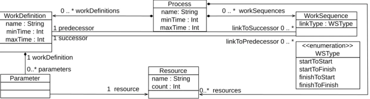
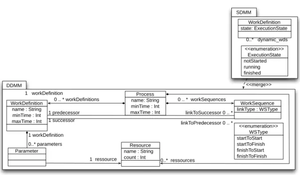
Domain-specific Modeling Languages startToStart startToFinish finishToStart finishToFinish <<enumeration>> WSType name: String minTime : Int maxTime : Int Process name : String minTime : Int maxTime : Int WorkDefinition linkType : WSType WorkSequence
Parameter name : String
count : Int Resource 0 .. * workDefinitions 1 successor 0 .. * workSequences 1 predecessor linkToSuccessor 0 .. * linkToPredecessor 0 .. * 0..* parameters 1 workDefinition 1 resource 0..* resources
Figure 2.1 — An extract of SPEM
language and must be consistent.
2.1.1 Abstract syntax of a DSML
An abstract syntax defines the structure of a language, the whole language concepts and their relationships. It is defined using a metamodeling framework, based on the MOF metametamodel, like the Eclipse-EMF/Ecore.
Many abstract syntaxes currently available also targets other uses like being the inputs for other tools and thus can suffer from other requirements and thus get away from the ini-tial purpose of giving a simple and minimal definition of domain concepts and relations. As a well known example, the UML metamodels suffer from many requirements like inter-change formats, diagrams supports, factorisation, etc.
SPEM is an OMG standard defined in order to specify and describe software and system development processes. A subset of the SPEM 2.0 is shown in Figure 2.1. It defines the concepts of Process composed of (1) a set of activities (WorkDefinition) performed during the process, (2) a set of dependencies (WorkSequence) that define temporal dependency relations (causality constraints) between activities and (3) a set of resources (Resource) allocated to activities (Parameter).
WorkDefinitions are related thanks to the WorkSequence concept, whose attribute linkType specifies when an activity can be started or finished. The values of kind are defined by the WSType enumeration. A WorkSequence value follows the stateToAction pattern (startToFinish type means that the target activity can only finish when the source activity has been started). As for the majority of modeling languages and due to the lack of expressivity of the graphical representation of metamodeling languages, the proposed SPEM metamodel does not capture the whole DSML requirements. For example, the requirement "workdefini-tion names have to be unique within a process" cannot be captured by the SPEM meta-model. Therefore, the DSML metamodel should be extended with well-formedness proper-ties which must be respected by the conforming models. OCL [OMG12] is the OMG stan-dard proposed to define such properties on models. It is a general-purpose textual formal language. OCL constraints are first order logic formulas defined as invariants for each
spe-2.1. Different elements defining a DSML
cific type associated to metaclasses (context). Its library defines the primitive and collection-related types and their predefined operations. In addition, OCL has an universal quantifier
f orAll and an existential quantifier exists and other iterators (select, one, etc.).
OCL allows to define structural properties at the metamodel level in order to validate them on the conforming models. To assess these properties, the DSML end-user can use OCL checkers like for example the Eclipse OCL checker3.
Considering the SPEM metamodel, Listing 2.1 defines an OCL property which verifies whether the workdefinitions’ names are unique on a process. In addition, the OCL property shown in the Listing 2.2 verifies the non-reflexivity of a worksequence.
context Process
inv names_uniqueness : s e l f. workDefinitions
−>forAll (wd1, wd2|wd1 <> wd2 implies wd1.name <> wd2.name) Listing 2.1 — OCL property verifying the uniqueness of workdefinitions’ names context WorkDefinition
inv not_reflexive :
s e l f. predecessor <> self . successor
Listing 2.2 — OCL property verifying the non-reflexivity of a worksequence
These properties define the static (or structural) semantics. It corresponds to defining restrictions on the structure of DSML conforming models.
2.1.2 Concrete syntax of a DSML
A concrete syntax describes a specific representation of the DSML used to display models to end users. It can be either a textual or graphical representation. It eases the use of the ab-stract syntax concepts and thus the creation of DSML conforming models. Several projects provide tools to implement textual concrete syntaxes for DSLS like Xtext4, TCS5, or
EMF-Text6 or graphical concrete syntaxes like Graphical Modeling Framework7 (GMF), Sirius8 and Graphiti9.
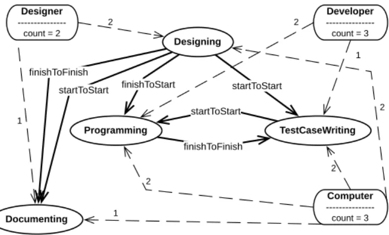
Figure 2.2 shows an example of a process model. It corresponds to a simplified devel-opment process composed of four activities, each represented with an ellipse: Programming, Designing, Test case writing and Documenting.
The “finishToStart” dependency between Designing and Programming means that Pro-gramming can only be started when Designing has been finished. Documenting and Test-CaseWriting can start once Designing is started (startToStart) and Documenting cannot finish if Designing is not finished (finishToFinish).
3http://www.eclipse.org/modeling/mdt/?project=ocl 4http://www.eclipse.org/Xtext/ 5http://www.eclipse.org/gmt/tcs/ 6http://www.emftext.org/ 7http://eclipse.org/gmf-tooling/ 8http://www.eclipse.org/sirius/ 9http://www.eclipse.org/graphiti/
Domain-specific Modeling Languages 2 2 2 finishToFinish Programming Documenting TestCaseWriting Designing
startToStart finishToStart startToStart
Developer ---count = 3 2 1 Designer ---count = 2 2 1 Computer ---count = 3 1 startToStart finishToFinish
Figure 2.2 — A SPEM development process
1 process Development {
2 wd Designing ( Designer ( 2 ) , Computer ( 2 ) )
3 wd Documenting ( Designer ( 1 ) , Computer ( 1 ) )
4 wd Programming ( Developer ( 2 ) , Computer ( 2 ) )
5 wd TestCaseWriting ( Developer ( 1 ) , Computer ( 2 ) )
6 ws finishToFinish from Designing to Documenting
7 ws s t a r t T o S t a r t from Designing to Documenting
8 ws f i n i s h T o S t a r t from Designing to Programming
9 ws s t a r t T o S t a r t from Designing to TestCaseWriting
10 ws finishToFinish from Programming to TestCaseWriting
11 ws s t a r t T o S t a r t from TestCaseWriting to Programming
12 rs Designer ( 2 )
13 rs Developer ( 3 )
14 rs Computer ( 3 )
15 }
Listing 2.3 — A textual formalization of the SPEM development process
The dependencies put between Programming and TestCaseWriting enforce a test driven development: programming can only start when test cases are already started and, obvi-ously, test case writing can only be finished when programming is finished in order to take into account test coverage.
Rounded rectangles represent resources with their amounts (2 Designers, 3 Developers and 3 Computers). Dashed arrows indicate how many occurrences of a resource an activity requires. On Figure 2.2, Programming needs two developers and two computers. Resources are allocated when an activity starts and freed when it finishes.
A concrete textual syntax for SPEM can be defined with Xtext. A possible formalization of the SPEM development process can be shown in Listing 2.3.
2.1.3 Behavioral semantics for a DSML
Usually, the behavioral semantics is neglected in the definition of a language. However, as we focus on executable DSML, it is a key feature to define the behavior of a model during
2.2. Model verification for DSMLs
the execution. It extends the static semantics defined on the DSML metamodel which is independent of the execution of a model and can be defined as well-formedness properties expressed with OCL. It is usually implicit as the names of the concepts and relations in the abstract syntax usually carry an intended meaning related to the semantics. However, if we want to correctly understand the signification of a DSML conforming model, it is mandatory to introduce an explicit semantics for the DSML that rigorously defines the meaning of the different DSML constructs. In addition, as we target the critical embedded systems in the POLARSYSproject10, the semantics of a DSML becomes a mandatory element to verify and to validate models defined earlier in the development process. There exists two main approaches to define a behavioral semantics [CRC+06]:
• operational semantics (the left side of Figure 2.3): It is expressed in the same technical space used for the definition of the DSML abstract syntax. It describes the execution of a model as a sequence of models expressed in the same language extended to rep-resent the state of the execution at a given step in time. This approach requires the extension of the DSML abstract syntax with the required elements to store the execu-tion informaexecu-tion. In the MDE context, to express an operaexecu-tional semantics, two kinds of approaches are proposed. The first one consists in using meta-programming languages like Kermeta or the EMF API for Java to specify imperatively the behavior of different language constructs. This approach extends metaclasses with operations that describe the evolution of a model. The second approach is based on endogenous model transfor-mations expressed on the abstract syntax using a model transformation language like ATL. It allows to declaratively define the behavior as a state transition system based on possible model states.
• denotational (translational) semantics (the right side of Figure 2.3): It is expressed in a technical space different from the DSML one. The target paradigm should be defined rigorously and adapted to the construction of powerful tools for analysis (like model-checking tools, simulators tools). In the MDE context, it consists in defining an exoge-nous model transformation that maps the DSML abstract syntax into the formal do-main to allow the use of the corresponding tools in this formal dodo-main. We detail this aspect for SPEM in the chapter 3.
2.2
Model verification for DSMLs
As we target safety critical systems, verification and validation (V&V) activities are manda-tory. We need to provide high quality tools for DSML end-users in that purpose. Model verification is a critical step in the development process. It consists in assessing the confor-mance of the designed models to the requirements relying on the DSML semantics.
A lot of activities have been conducted in the last 20 years regarding the integration of formal V&V for DSML (see [BGHM05, BCL+01, RKK08, RL12, Rus11, DMGB09, GdLMD09, RKK08, PIM09, GCKK06]).
10http://polarsys.org/