HAL Id: hal-01144336
https://hal.archives-ouvertes.fr/hal-01144336
Submitted on 21 Apr 2015
HAL is a multi-disciplinary open access
archive for the deposit and dissemination of
sci-entific research documents, whether they are
pub-lished or not. The documents may come from
teaching and research institutions in France or
abroad, or from public or private research centers.
L’archive ouverte pluridisciplinaire HAL, est
destinée au dépôt et à la diffusion de documents
scientifiques de niveau recherche, publiés ou non,
émanant des établissements d’enseignement et de
recherche français ou étrangers, des laboratoires
publics ou privés.
Reliable Expanded Beam Connector Compliant with
Single-mode Fiber Transmission at 10 Gbit/s
Sy Dat Le, Michel Gadonna, Monique Thual, Lionel Quetel, Jean-François
Riboulet, Vincent Metzger, Douglas Parker, Alain Philippe, Sébastien Claudot
To cite this version:
Sy Dat Le, Michel Gadonna, Monique Thual, Lionel Quetel, Jean-François Riboulet, et al.. Reliable
Expanded Beam Connector Compliant with Single-mode Fiber Transmission at 10 Gbit/s. Optical
Fiber Communication Conference (OFC 2015), Mar 2015, Los Angeles, United States. pp.W4B.5,
�10.1364/OFC.2015.W4B.5�. �hal-01144336�
Reliable Expanded Beam Connector Compliant with
Single-mode Fiber Transmission at 10 Gbit/s
Sy Dat Le1, Michel Gadonna2, Monique Thual1,, Lionel Quetel3, Jean-Francois Riboulet3, Vincent Metzger4,
Douglas Parker4, Alain Philippe4, and Sebastien Claudot4
1 CNRS, UMR Foton, Université de Rennes 1, IUT Lannion, F-22305 Lannion, France 2Institut Mines-Telecom, Télécom Bretagne F-29285 Brest, France 3IDIL Fibres Optiques, 21 rue Louis De Broglie 22300 Lannion France 4Souriau-Sunbank - Esterline ECT, RD323, 72470 Champagné, France
[email protected] / [email protected] / [email protected]
Abstract: A new microlens design brings together benefits of physical contact and expanded
beam technologies resulting in a reliable single-mode fiber connection requiring low maintenance for 10 Gbit/s networks as the Fiber-To-The-Home.
OCIS codes: (060.0060) Fiber optics and optical communications; (060.2340) Fiber optics components 1. Introduction
Fiber-To-The-Home (FTTH) and Fiber-To-The-Antenna (FTTA) deployment is becoming a reality with the recent flow-rate increased demands by full High Definition Television (HDTV), the fourth generation of mobile phone (4G) and Web Office. Whether one or several network topologies exist, all converge to have at least one connection at the server location side (OLT - Optical Line Termination) and/or one connection at the end-user location side (ONU - Optical Network Unit). Network designers are more likely to use single-mode fiber (SMF) for complying with higher data rates of about 10 Gbit/s and powerful laser sources (as the $/W ratio is continually decreasing) for covering a larger number of end-users with only one laser source associated with several passive couplers.
But typical SMF connectors have performance dramatically degraded by contaminants and laser power [1]. So what will be the time and money allocated by the service provider for the maintenance of such connectors?
This article proposes to use a microlens design minimizing the number of interfaces to combine the benefits of butt-joint and expanded beam lens technology all together into a mechanical footprint compliant with telecom standards. Modeling, manufacturing and testing at the wavelength of 1550 nm are presented here and lead to a new SMF connector tolerant to contamination, with a high laser damage threshold and reliable for 10 Gbit/s optical transmission data rate.
2. Principle and theoretical concepts of the proposed solution
The principle of the proposed solution consists of introducing a microlens at a single-mode fiber (SMF) end to expand its mode field diameter [2]. For that purpose a graded index fiber (GIF) section is spliced at the SMF end (see Fig. 1a). Thanks to the parabolic refractive index transverse profile, the propagation of the Gaussian beam is periodic in GIF. The index profile is considered to be a perfect parabolic curve conforming to the relationship:
n(r)2=n
02(1-2r2/a2), n0 is the central refractive index, is the relative index difference between n0 and nc (the refractive index of the GIF cladding) defined as = (n02-nc2)/(2n02), r the radial position in relation to the optical axis and a the core radius of the GIF. The numerical aperture (NA) is (n02-n
c2)½= nc (2)½.
Using the GIF index profile and the core diameter we observe the propagation of the Gaussian beam in the microlens. This characterizes the Gaussian beam diameter (2), the Gaussian beam waist (20), where the phase front is plane, and the working distance zw, which is the distance between the beam waist location and the GIF end
as shown in Fig. 1a. First we perform an analytical calculation based on the Kogelnik method [3] and then a second kind of simulation based on BPM (beam propagation method [4]). This allows us to take into account the beam truncation by the GIF cladding during the beam propagation in this GIF segment.
The beam waist and working distance depend on the GIF segment length as can be seen in Fig. 1b. The beam diameter in the GIF segment initially increases to its maximum 2max at LGIopt before converging to its input beam
diameter at 2LGIopt. The value of LGIopt depends on the GI refractive index profile and its core diameter. Defining the
GIF parameter as g = (2)1/2/a, the optimal GIF length is given by L
GIopt=/(2g) [2]. The GIF fiber is cleaved at the
optimal distance LGIopt from the GIF/SMF splice. In this configuration, as the phase front is plane at the fiber end,
the fiber diameter remains 125 µm over the length of the microlens, it is suitable to be inserted in a standard connector ferule.
The computation of beam propagation inside the GIF section is also performed by a BPM analysis by solving the scalar Helmholtz equation (2+k2)U(x,y,z)=0, where k=2πn(r)/λ is the spatially dependent propagation constant
at wavelength λ, U(x,y,z) = A(x,y,z)exp(ikcz) is the complex scalar wave amplitude with A(x,y,z) the slowly varying beam amplitude and kc=2πnc/λ the propagation constant in cladding. In the simulation, the input beam amplitude profile is Gaussian. The field is sampled on an N×N grid along x and y axes. The core index of GI sections is slightly varied as a function of radius r by the grid. Assuming the weakly guiding conditions, the field propagation along z-axis is simulated by a split-step Fourier BPM with a step of dz [5].
Fig. 1. (a) Principle of the SMF-GIF microlens, (b) calculation of beam waist and working distance based on the analytical method and BPM
method, and (c) calculation of 55 µm beam waist coupling losses for different angular misalignments and axial gap related to lateral offset.
Fig. 1c shows the coupling efficiency of two optical fibers with a beam waist of 55 µm with respect to lateral offset misalignment for different cases of axial (0 and 200 µm) and tilt misalignment (from 0° to 0.5°). Because of this large beam waist, no increased loss is observed for a gap between fiber ends from 0 up to 200 µm (dash or blue curve) compared to the ideal coupling (solid or red curve). Since the fibers ends will be put in contact in connectors, the gap will be less than one µm, so, no increased loss from axial misalignment will be observed. In the same way, the offset has little impact on signal losses. A 2 µm offset leads to less than 0.1 dB excess loss. However, the coupling losses increase rapidly with an increasingly misaligned angular offset. For 55 µm beam waist, a 0.5 degree tilt misalignment leads to 2 dB excess loss (curve with triangle or cyan marks). The larger the fiber beam waist output, the more tolerant to axial and lateral misalignment are the coupling and the more critical is the angular positioning tolerances. A tradeoff can be found between the gap and lateral offset tolerances on one hand and the tilt tolerances on the other hand.
3. Results and characterizations
To produce the large beam waist connection, each ferule connector contains a GIF section with a length of LGI
spliced to a SMF, so the total length of two GIF sections is 2×LGI. First we measure the insertion loss with a GIF
length of 2×LGI spliced in between two SMFs. The measurement shows a minimum loss of about 0.4 dB around the
calculated LGIopt (the filled round or green curve, Fig. 2a). It gives idea projection of the expected insertion loss when
the two connectors are mated and correctly coupled.
Then, we fabricate SMF-GIF microlens fibers (SMF-GIF) with GIF length, LGI, varying around LGIopt±30 µm in
order to measure the beam waist by the far-field method. The measurements show the change of beam waist with the length of GIF section as can be seen in Fig. 2a. We measure a maximum beam waist of about 55 µm for a given GIF length equal to the calculated LGIopt. The maximum beam waist corresponds to the minimum insertion loss (0.4dB).
So by measuring the insertion losses and the beam waist, we confirm the optimal length of GIF section, LGIopt, as
the theoretical calculation. Therefore, the SMF-GIF with the GIF section length of LGIopt is prepared for use as the
connector expanded beam lens. The measurements of fiber-to-fiber coupling losses for several SMF-GIF pairs with
LGI equal to LGIopt and LGIopt±10µm have been performed. The coupling losses for bare SMF-GIF fibers are about
0.5 dB. It increases to about 0.9 dB for SMF-GIF LC/PC connectors. This can be explained by the imperfect alignment of the two connectors. Referring to the calculation, for 55 µm beam waist the coupling loss is 0.4 dB if two beams are tilted at 0.2 degree. Misalignments could arise from ferule positioning or SMF-GIF fiber ends. Optical return losses of the connectors are also measured by an optical coherence-domain reflectometer with a high sensitivity (100 dB) and high spatial resolution (50 µm). The reflection at the SMF/GIF splice is about 70 dB and at the surface of the connector with air gap is about 30 dB.
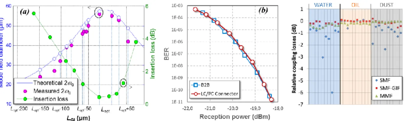
Fig. 2. (a) measurement of insertion losses, and beam waist of SMF-GIF LC/PC connectors, (b) BER measurement of the SMF-GIF LC/PC
connector in FTTH systems at 10 Gbit/s, and (c) coupling losses measurement with 3 contaminants (oil, water, dust) relative to without contaminant of SMF-GIF LC/PC connectors compared with MMF and SMF (10 times for each).
Several pairs of SMF-GIF LC/PC connectors with 55 µm beam waist are put in a test platform for FTTH applications. To test the connector efficiency in XG-PON2, the 10 Gbit/s non-return-to-zero optical signal at the wavelength of 1550 nm is used. It is encoded with a pseudo-random bit sequence (PRBS) of 231−1 pattern length.
Fig. 2b shows an example of the bit-error-rate (BER) measurement of the connectors compared to the back-to-back (B2B) case. No penalty is observed. We have demonstrated the use of large mode LC/PC connectors at 10 Gbit/s in FTTH systems. The connectors could be suitable for higher bit-rates.
The robustness of the SMF-GIF interface of the LC/PC connectors has been evaluated in the presence of three contaminants: oil (0.03 ml droplet), water (0.03 ml droplet), and dust particles (Fig. 2c). On this figure, the relative coupling loss is considered referred to the preliminary coupling loss of a connection without contaminant for three fiber types: SMF, SMF-GIF, and multi-mode fiber (MMF). These measurements show that the SMF-GIF version has a better behavior than the SMF and similar to the MMF in the presence of contamination. The physical contact (PC) technology is able to exclude the liquid from the interface due to the high pressure of the spring loading which leads to low optical loss with water contamination. With solid particle contamination, it is a matter of statistical particle distribution over the core area; when the remaining area for passing light becomes smaller, the coupling losses increase accordingly. More, the larger beam waist increases the damage threshold to 1 W against 0.04 W for standard angled physical contact (APC) SMF connectors as the power before failure is proportional to the beam area or the square of the beam waist.
4. Discussion and conclusions
This study clearly identifies the actual limits of the optical connection technology to cope with future fiber optics application requiring SMF. The study shows the capability of enlarging the light beam at the connection interface without increasing the number of Fresnel reflective interfaces. The simulation based on a GIF with 125 µm cladding shows the capability to increase 25 times the area correlated by the first production batches and measurements. The robust performance during testing confirms that the GIF combined with micro-welded/fused and cutting technology allows manufacturing of a single-mode PC expanded beam (EB) fiber optic interface as rugged as for conventional multimode PC fiber optic interconnection. The technology is thus called “expanded beam physical contact”. This approach utilizes the best features of PC and EB technology. As it is, the design can already be adapted to several existing network connectivity platforms such as SC, LC, MPO contacts and connectors.
5. Acknowledgement
This work is financed by French government R&D funding.
6. References
[1] D. S. Kokkinos, C. Saravanos, W. Stanford, W. Wang, and Y. Hua, “SC/APC Fiber Optic Connectors Connected and Disconnected under High Optical Power,” in Optical Fiber Communication Conference and Exposition and The National Fiber Optic Engineers Conference, Technical Digest (CD) (Optical Society of America, 2006), paper NTuA5.
[2] M. Thual, P. Rochard, P. Chanclou, and L. Quetel, C. van Trigt, “Contribution to research on Micro-Lensed Fibers for Modes Coupling,” Fiber and Integrated Optics, vol.27, no.6, pp. 532-541 (2008).
[3] H. Kogelnik, “Coupling and conversion coefficients for optical modes,” in Proceeding Symposium Quasi-Optics, vol.14, pp. 333-347 (1964). [4] M. D. Feit and J. A. Fleck, Jr., “Light propagation in graded-index optical fibers,” Appl. Opt., vol. 17, no. 24, pp. 3990–3998 (1978). [5] J. Van Roey, J. van der Donk, and P. E. Lagasse, “Beam-propagation method: analysis and assessment,” J. Opt. Soc. Am., vol.71, pp. 803-810 (1981).