HAL Id: hal-03093049
https://hal.archives-ouvertes.fr/hal-03093049
Submitted on 3 Jan 2021HAL is a multi-disciplinary open access archive for the deposit and dissemination of sci-entific research documents, whether they are pub-lished or not. The documents may come from teaching and research institutions in France or abroad, or from public or private research centers.
L’archive ouverte pluridisciplinaire HAL, est destinée au dépôt et à la diffusion de documents scientifiques de niveau recherche, publiés ou non, émanant des établissements d’enseignement et de recherche français ou étrangers, des laboratoires publics ou privés.
The formation of a cobalt-based glaze layer at high
temperature: a layered structure
Alixe Dreano, Siegfried Fouvry, Sergio Sao-Joao, Jules Galipaud, Gaylord
Guillonneau
To cite this version:
Alixe Dreano, Siegfried Fouvry, Sergio Sao-Joao, Jules Galipaud, Gaylord Guillonneau. The formation of a cobalt-based glaze layer at high temperature: a layered structure. Wear, Elsevier, 2019, 440-441, pp.203101. �10.1016/j.wear.2019.203101�. �hal-03093049�
1
The formation of a cobalt-based glaze layer at high temperature: a
layered structure
Alixe Dreano*,1, Siegfried Fouvry1, Sergio Sao-Joao2, Jules Galipaud1, Gaylord Guillonneau1
1 University of Lyon, Ecole Centrale de Lyon, LTDS UMR 5513, Ecully, France 2
University of Lyon, Ecole des Mines de Saint-Etienne, LGF UMR 5307, Saint-Etienne, France * Corresponding author E-mail address: [email protected] (A. Dreano)
Abstract
The purpose of this study is to investigate the protective glaze layer structure formed during high temperature fretting wear process. The studied material is a cobalt-based alloy with a Cr-Ni-W solid solution (HS25) fretted against an alumina sample. It appears that a protective third body is spontaneously created at the interface for temperatures above 400°C. The excellent tribological properties of the glaze layer leads to a stabilized friction coefficient of 0.3 and a quasi no-wear regime.
Microstructure observations at the micro- and nanoscale were performed and revealed that the high temperature glaze layer is not homogeneous but rather composed of three layers with different grain sizes and chemical compositions. The investigations show that the effective glaze layer, the layer able to resist to fretting wear, is a thin layer made of nanocrystalline cobalt oxides. However, the chemical analysis reveals that before the formation of the effective glaze layer, the interface displays a high content of chromium oxides. Hence, a chemical segregation happens leading to the formation of a cobalt-rich effective glaze layer on the top of the former chromium-rich layer. In the light of these results, a chemical mechanism involving the consumption of chromium during the running-in wear stage is proposed to describe the glaze layer formation.
Keywords
2 1. Introduction
The rheology and nature of debris particles is an important aspect to be consider when describing their action on tribological systems [1]. When the debris-bed layer is powdered and non-cohesive, it promotes a severe wear whereas a cohesive debris-bed layer will lead to a mild-wear regime [2]. It is well known that the high-temperature wear of metals involves the formation of a wear-resistant layer at the interface usually called « glaze layer » [3]. Many authors agreed with the fact that this tribolayer is made of oxide particles generated at the beginning of the sliding process which are stuck into the interface, compacted and even sintered [4,5]. Jiang has showed that the compaction of triboparticulates is promoted by elevated temperatures and small grain sizes [4]. Moreover, the tribosintering process is also affected by the chemical nature of the wear debris [6]. The sintering process is driven by the capacity of chemical species to diffuse from one grain to another. Hence, some authors have pointed the importance of the diffusive properties of the oxides involved in the formation of a protective oxide layer, such as the glaze layer [6,7]. It has been shown that the high temperature wear of pure cobalt leads the formation of a glaze layer whereas the glaze layer does not form for pure chromium. Hence, for a Co-Cr alloy (HS25) the glaze layer formation is due to the capacity of cobalt to diffuse faster in its own oxide Co3O4 than chromium in Cr2O3[7].
According to the literature, the glaze layer is made of nanocrystallized grains [8–10] but some authors have emphasized the presence of amorphous zones [9,11]. The nanocrystalline materials are known to present exceptional strength as well as high hardness leading to an increasing use of these materials since they better resist to wear than microcrystalline materials [12,13]. Some authors have reported that the glaze layer is harder than the bulk material [14,15], hence it increases the wear resistance at the interface and limits metal/metal interactions.
This investigation is focused on the morphology and the tribochemical nature of the glaze layer formed on a cobalt-based alloy (HS25) subjected to fretting wear at 575°C against alumina. Cobalt-based alloys are commonly used in industry for their good mechanical properties and resistance to corrosion [16,17]. The Haynes alloy HS25 contains a Cr-Ni-W-C solid solution embedded in a cobalt matrix where chromium provides strength and corrosion resistance by creating carbides and a protective layer of chromium oxides Cr2O3 [18]. Alumina is chosen for its chemical inertness and its capacity to resist fretting wear [5,19]. Hence,
the present study focus only on the wear mechanism of the cobalt-based alloy. It has been shown that the wear mechanism below 150°C is driven by a synergistic action of oxidation and abrasion whereas a protective oxide layer is formed for higher temperatures [5,19].
2. Experiments 2.1. Fretting tests
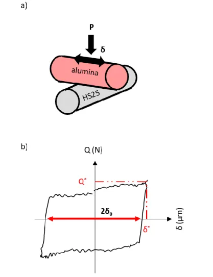
The high-temperature fretting bench used for this study was previously presented in [19]. The studied tribocouple was constituted of an alumina and a Haynes 25 rods crossed at 90° as presented in Fig. 1 a). Both had a radius of 4 mm. A normal force P was applied to the system and a displacement δ was imposed. During fretting, the frequency f and the number of fretting cycles N were fixed and the tangential force Q was
3
recorded. The temperature T was also controlled and preliminary tests had warranted that the temperature at the contact point was correct (with no fretting solicitations).
Fig. 1: a) Alumina/HS25 cross-cylinders configuration and b) fretting loop
Fig. 1 b) shows a typical fretting loop recorded during the tests at high temperature. The sliding amplitude δ0 which was defined as the residual displacement measured when Q = 0, well approximated the
effective displacement operating in the interface [19]. A friction coefficient µ was also defined for each fretting cycle as follows:
(1)
Where Q* was the maximum tangential force during the cycle. Table 1 presents the tribological parameters imparted to the tribosystem.
Table 1: Loading parameters
Frequency, f (Hz) 50
Sliding Amplitude, δ0 (µm) ± 20
Normal force, P (N) 50
Number of fretting cycles, N 200 000
Contact Temperature, T (°C) 1. From ambient to 600°C 2. 575°C
4
After testing, the samples were cleaned in an ultrasonic bath with ethanol. Wear volumes were measured by profilometry and were defined by the missing volume in the wear track:
(2)
Where V- and V+ were respectively the volumes below and above the unworn surface. Alumina was chosen for its high mechanical resistance and chemical inertness. Previous studies [5,19] demonstrated that this counterbody did not wear away, and wear was only detected on the HS25 samples. Hence, wear measurements were only performed on the HS25 rods.
2.2. Haynes 25
The chemical composition of the HS25 is presented in Table 2. The alloying elements are in solid solution or in the form of carbides in the FCC cobalt lattice.
Table 2: Nominal composition of the Haynes 25 alloy (at. %) measured by SEM-EDX
Co Cr Ni W Fe Mn
53.8 ± 0.07 25.8 ± 0.16 11.0 ± 0.10 5.15 ± 0.01 2.41 ± 0.03 1.83 ± 0.08
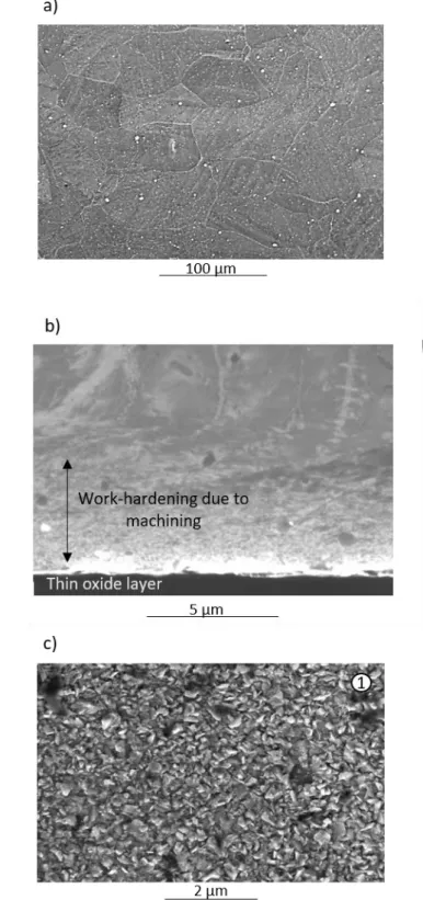
The core microstructure of the HS25 is presented in Fig. 2 a). The alloy was heat-treated at 1185°C during 30 min and water quenched, inducing the presence of large grains of around 66 µm in diameter and including many crystals’ defects such as twins and carbides at the grain boundaries. Fig. 2 b) presents the microstructure near the surface before the fretting solicitation. Due to machining, a 5 µm depth work hardening is observed. Nano-indentation tests revealed that the hardness is 1.8 times higher near the surface than in the bulk metal. Hence, the bulk hardness is equal to 251 Hv whereas the surface hardness increases up to 452 Hv (at ambient temperature). This increase in hardness may be due to the increase in residual stress and dislocation density as well as the decrease in grain size. By assuming an elastic Hertzian contact, the maximum contact pressure can be calculated as presented in a previous work [19] and is equal to 2.3 GPa (at ambient temperature). Then, plastic deformation was activated which was enhanced by the increase in temperature and the corresponding reduction of the mechanical properties of the Haynes 25 alloy [19].
Finally, Fig. 2 c) shows the morphology of the oxides after 2 h of corrosion at 575°C in air. The cross-section presented in Fig. 2 b) confirms that the oxide layer was very thin, around 200 nm. A very thin oxide layer is common for alloys enriched in chromium where its role is to rapidly form Cr2O3 oxides able to protect
5
Fig. 2: SE-SEM micrographs of : a) the core microstructure after mechanical polishing; b) the cross-section microstructure of the interface after an exposure at 575°C in air for 2 h (a smooth ionic abrasion was done to reveal the
microstructure); c) the transient oxidation of the alloy in top view after an exposure at 575°C for 2 h.
2.1. Wear track characterizations
The wear tracks were observed with the help of an optical microscope and a SEM (FEG Mira 3 TESCAN) using an accelerating voltage of 5 kV. The EDX quantifications were performed with an Oxford Instruments
6
system at 20 kV. Cross-sections were made mechanically (cutting and grinding) or by FIB machining with a Dual Beam FEI Helios 600i. A TEM lamella was also machined by FIB with an accelerating voltage of 30 kV with adapted current values for the shaping step and with an accelerating voltage of 5 kV for the cleaning step. The final thickness of the lamella was around 90 nm. TEM observations were performed with a JEOL JEM 2100 equipped with an EDX detector (Oxford Instruments) at an accelerating voltage of 200 kV.
Some wear tracks were also analyzed using XPS (Ulvac-Phi Versaprobe II) from the top surface. An ionic etching with Ar+ ions accelerated at 500 V was carried out in order to remove the surface contamination. An aluminum Kα X-ray source (1486.6 eV) was used and spectra were calibrated with the C 1s photopeak at
284.8 eV attributed to the adventitious carbon. First, survey spectra were recorded from 0 to 1100 eV with a pass energy of 187 eV in order to identify all the elements. Then, high resolution spectra were performed with a low pass energy (23 eV) for the most interesting elements. The high resolution spectra were fitted and analyzed thanks to the PHI Multipack software. Semi-quantification was performed on high resolution spectra by considering the sensitivity coefficient of each element. Throughout the experiments, a spot size of 50 µm was used.
3. Tribological analysis
3.1. Effect of temperature on friction and wear
Fig. 3 displays the evolution of the wear volume and the corresponding mean friction coefficient as functions of temperature. As previously shown in [5,19], the involved wear mechanism is strongly dependent on temperature.
- At low temperature ( ), the wear mechanism is oxido-abrasive where both abrasion and oxidation phenomena lead to a continuous increase in wear. The friction coefficient varies between 0.55 and 0.3. The associated wear track in Fig. 3 shows the presence of abrasive grooves covered with an oxidized wear debris-bed layer (black oxides).
- At high temperature ( ), the wear volume is much smaller. The associated SEM image the wear track (Fig. 3) shows the presence of a smooth layer which covers all the interface. This layer is usually called “glaze layer” and leads to a sharp reduction of wear and a slight reduction of the friction coefficient (µGL = 0.3).
At high temperature, the glaze layer is formed by a sintering process of the wear particles [6,7]. Hence, the friction coefficient and the wear volume are stable and low. To better clarify the tribo-sintering process, the different stages of the glaze layer formation at high temperature are deeply investigated in this study.
7
Fig. 3: Evolution of wear and friction coefficient with temperature. Optical micrographs are related to fretting test at 100°C and 575°C, respectively (P = 50 N; δ0 = ± 20 µm; f = 50 Hz; N = 200 000)
3.2. Wear kinetics at high temperature (575°C)
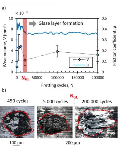
Fig. 4 a) displays the evolution of the friction coefficient and wear with fretting cycles during a fretting test performed at 575°C. Fig. 4 b) shows some optical images of the wear tracks at 450, 5 000 and 200 000 cycles.
At the very beginning of the test, at 450 cycles (9 s of fretting wear), the friction coefficient is maximum, around 0.5. The wear volume is very low and the associated optical image reveals that the center of the wear track is not covered by the black oxides as observed at the border. Then, the access of oxygen is very limited due to the fretting solicitation and the metal/ceramic interaction promotes a high friction coefficient [20,21]. After 450 cycles, the friction coefficient starts to decrease until 20 000 cycles. The interrupted fretting tests show the presence of a homogeneous oxide debris-bed layer over the whole interface as presented in Fig. 4 b) at 5 000 cycles (100 s of fretting-wear). It is clear that the glaze layer is not yet created within the interface and hence does not explain the decrease in the friction coefficient, but rather its stability at a low value (0.35). The wear volume evolution in Fig. 4 a) displays an increased trend until 20 000 cycles and then shows a plateau evolution. The synergistic increase in wear and decrease in friction during the transient period is probably due to the fact that more and more debris are present inside the contact. The loose debris-bed layer lowers the friction coefficient via a better shear stress accommodation. On the other hand, these debris particles are completely evacuated from the wear track during the post-test cleaning procedure leading to an increase in the measured wear volume. During a long duration test, these loose particles are compacted and sintered into the glaze layer.
8
Fig. 4: a) Evolution of the friction coefficient and the wear volume during fretting at 575°C; b) optical images of the wear tracks after 450, 5 000 and 200 000 cycles (P = 50 N; δ0 = ± 20 µm; f = 50 Hz; T = 575°C)
It can be stated that the glaze layer formation starts around 20 000 cycles since Fig. 4 b) shows that there is no glaze layer before 20 000 cycles and that there is one after. Moreover, the friction coefficient and the wear volume remain constant and low starting from 20 000 cycles. Hence, a necessary number of fretting cycles NGL is introduced to capture the glaze layer transition at high temperature. Former
investigations [5,6] show that the NGL number is directly related to the tribo-sintering process and hence
depends on various tribological parameters such as the operating temperature or the time allowed for particles to be welded (inverse of the frequency), according to Eq. 3. Then, the evolution of wear at high temperature can be predicted by considering only the dissipated friction energy when N < NGL. In that case,
the energetic wear coefficient α is positive. Otherwise, for N ≥ NGL, it is equal to zero. The glaze layer is then
able to completely dissipate the friction energy in some way other than the formation and ejection of debris particles.
(
)
(3)
Where SGL is a constant (mm².s), R the universal constant, Ea the activation energy (J/mol), T the
9
4. Characterization of the tribolayer formed at high temperature (575°C) 4.1. Macroscopic observations
Fig. 5 a) presents some details of the wear track fretted for 5 000 cycles at 575°C (N < NGL). Fig 5 b)
presents the same observation but after 200 000 cycles of fretting (N ≥ NGL). Figs. 5 a.1) and b.1) show some
details of the fretted interfaces at N = 5 000 and N = 200 000 in top view. Figs. 5 a.2) and b.2) present the cross-section micrographs of the wear tracks, performed by FIB machining before the glaze layer formation (N = 5 000) and by mechanical machining and polishing after its formation (N = 200 000). Figs. 5 a.3) and b.3) compare the EDX linescans performed through the interfaces. In order to better interpret the evolution of the chemical composition, a ratio method is preferred (Co/Cr, O/M where M is equal to Co+Cr). For the HS25 alloy, the Co/Cr ratio is equal to 2 (calculated from Table 2). When the ratio is lower than 2, it means that there is a cobalt depletion, whereas a depletion of chromium is observed when the ratio is higher than 2. Hence, the Co/Cr ratio indicates how the chemical elements behave during the wear process.
Fig. 5 a.1) shows that at 5 000 cycles, the interface is covered by a powdered wear debris-bed layer. The cross-section image presented in Fig. 5 a.2) reveals that the thickness of the debris interface is around 2-3 µm and presents some porosities or cracks. The O/M ratio, displayed in Fig. 5 a.3), shows that the third body is oxidized. Hence, this oxide layer is called “MOL” for “Mixed Oxide Layer”. Below the mixed oxide layer, there is a thin layer enriched with chromium, as seen in Fig. 5 a.3), which is referred to as “CRL” for “Chromium-Rich Layer”. Indeed, the chromium-rich layer presents a lower Co/Cr ratio than the bulk material which means that there is an enrichment with chromium in this area. The slight depletion of chromium just below the chromium-rich layer, in the HS25 substrate, indicates a diffusion process of chromium from the bulk material towards the oxide layer [22]. In the literature, some authors [14,23,24] indicate that the chromium-rich layer is the result of the diffusion of anions (O2-) through the oxide layer which first reacts with the chromium elements to form the internal Cr2O3 oxide layer.
The O/M ratio remains constant which means that there is a constant content in oxygen and metals in the mixed oxide layer. The Co/Cr ratio variation in the mixed oxide layer confirms the variation of one metallic element content compared to the other. The ratio is maximum near the surface (Co/Cr = 3) and tends to decrease towards the initial ratio (Co/Cr = 2), which means that there is a chromium depletion in the mixed oxide layer. The maximum chromium depletion is observed at the interface, according to the resolution of the EDX measurements.
10
Fig. 5: a) Observation of the wear track before the glaze layer formation (N=5 000) by SEM-SE imaging in top view (a.1), in cross-section after FIB machining (a.2) and corresponding EDX linescan analysis displaying the O/M and Co/Cr ratios evolution (a.3); b)
observation of the wear track after the glaze layer formation (N=200 000) by SEM-SE imaging in top view (b.1), in cross-section after mechanical polishing (b.2) and associated EDX linescan analysis (b.3). CoRL stands for “Cobalt-Rich Layer”, MOL for “Mixed
11
Fig. 5 b.1) confirms the presence of a smooth and protective glaze layer, on the top of the wear track after being fretted for 200 000 cycles. The cross-section image presented in Fig. 5 b.2) is quite similar to that of the cross-section interface before the glaze layer formation (Fig. 5 a.2)) with the presence of a chromium-rich layer (CRL) and a thick mixed oxide layer (MOL). However, above the MOL, a thin top layer displaying a high cobalt content is observed. This so-called Cobalt-Rich Layer (CoRL) appears to be the effective glaze layer since it is only observed after the NGL transition, where the low friction plateau evolution and the
no-wear regime are established (Fig. 4). The EDX measurements displayed in Fig. 5 b.3) shows that the oxygen content is much higher at 200 000 cycles than at 5 000 cycles, according to the higher value of the O/M ratio. The mixed oxide layer presents a stable Co/Cr ratio with a slight chromium depletion. The effective glaze layer displays a more pronounced chromium depletion than at 5 000 cycles (Co/Cr = 4.5 at 200 000 cycles and Co/Cr = 3 at 5 000 cycles). Hence, the effective glaze layer seems to be richer in cobalt than in chromium.
4.2. Extreme surface chemical analysis
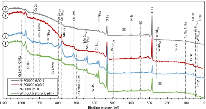
Fig. 6 displays XPS survey spectra acquired for different tribological conditions. First, a survey spectrum (1) was acquired outside the wear track, where the HS25 sample underwent hot corrosion at 575°C for 2h, as presented in Fig. 2 c). The second spectrum (2) was acquired in the wear track after 5 000 cycles of fretting at 575°C. The associated wear track is showed in Fig. 5 a.1). Then, two spectra were acquired after 200 000 cycles of high-temperature fretting. The spectrum (3) was acquired in the CoRL (effective glaze layer) whereas the spectrum (4) was acquired in a mixed oxide layer (MOL) as presented in Fig. 5 b.1). The topography of the wear track in Fig. 5 b.1 confirms that the cobalt-rich layer is laying on the mixed oxide layer and thus that some CoRL sheets are sometimes ejected out of the interface revealing the MOL sub-layer.
Fig. 6: Survey XPS spectra performed in the wear tracks at different number of fretting cycles and without fretting at 575°C. Spot (1) is localized in Fig. 2 and spots (2), (3) and (4) are localized in Fig. 5. The lines with no reference (grey crosses) are considered as impurities and represents from the low to the high binding energies: Ar 2p; Ca 2p; Ca 2s.
12
The XPS spectra show that the main elements of the alloy are detected in all cases (Co, Cr, W, Mn) but with different intensities. In contrast, nickel is scarcely detected (Ni 2p3/2) since this element has bad
oxidation and diffusion properties [7]. Oxygen O 1s and O 2s peaks are also detected in all the spectra, as well as a small quantity of nitrogen N 1s, around 2% of the global semi-quantification. Even if some authors [25,26] have emphasized the role of nitrogen in the formation of some tribological transformed structures on titanium alloy, here it is not the relevant element regarding the glaze layer formation, which is mainly controlled by an oxidation process. In addition, it is interesting to notice that there is no peak of aluminum showing that there is no transfer from the alumina counterface.
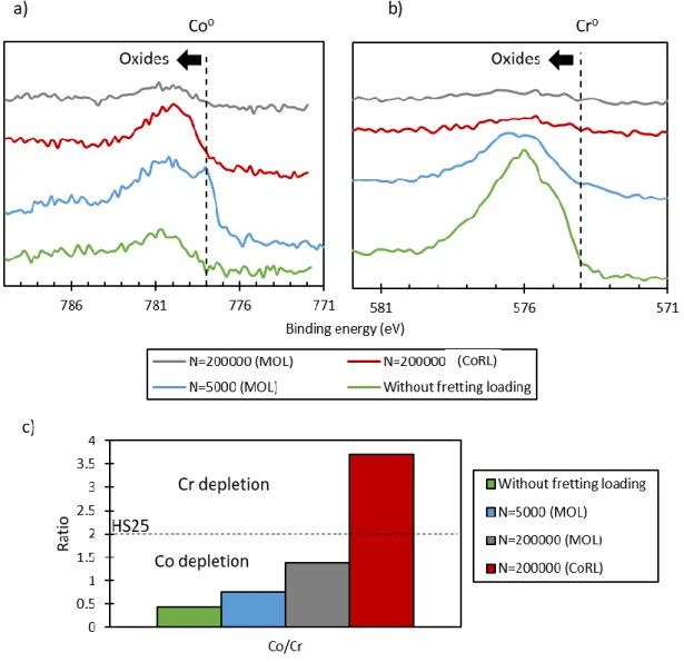
Fig. 7: High resolution XPS analysis: a) evolution of Co 2p3/2 with fretting cycles; b) equivalent analysis for Cr 2p3/2; c)
evolution of the corresponding Co/Cr (at. %). CoRL stands for “Cobalt-Rich Layer” and MOL for “Mixed Oxide Layer”
Figs. 7 a) and b) present respectively the high resolution spectra of Co 2p3/2 and Cr 2p3/2 for the four
zones of interest. Two main chemical environments can be evidenced. The first one corresponds to the zero oxidation state Co0 and Cr0 and the other one corresponds to the oxidized form of the species (higher binding energies). Moreover, the intensities of the peaks are different depending on the analyzed zone. It is clear that there is almost no chromium at 200 000 cycles. The high intensity of the Cr 2p3/2 peaks outside the wear tracks and before the glaze layer formation (N < NGL) confirms the readiness of chromium to be
13
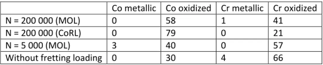
different intensities. A deconvolution process was performed on high resolution spectra to first distinguish the percentage of pure metal compared to the oxidized form, as presented in Table 3. According to Table 3, all the chromium is oxidized in the first 5 nm of the surface after 5 000 cycles of fretting-wear (57%). Outside the wear track, a great proportion of chromium is also oxidized (66%) even if some traces of metallic chromium are detected (4%). Outside the wear track, all the cobalt is also oxidized whereas some traces of metallic cobalt are detected after 5 000 cycles of wear (3%). After 200 000 cycles, there is a bigger proportion of cobalt compared to chromium. In the CoRL and in the MOL, all the cobalt elements are oxidized (79 and 58%).
A semi-quantitative analysis was extracted from the high resolution XPS spectra. The Co/Cr ratio involves both oxidized and unoxidized states. Results are summarized in Fig. 7 c). The Co/Cr ratio shows a chromium depletion in the effective glaze layer (CoRL) whereas a cobalt depletion is observed in the mixed oxide layer and during hot corrosion. At 5000 cycles and without fretting loading, the ratio is equal to 0.77, which is slightly more than outside the wear track (0.43). At 200 000 cycles, the mixed oxide layer still presents a cobalt depletion but less severe than that observed at 5 000 cycles.
Table 3: Contents (at. %) in cobalt and chromium (oxidized or not) in the four zones analyzed by XPS. CoRL refers to the Cobalt-Rich Layer and MOL to the Mixed Oxide Layer.
Co metallic Co oxidized Cr metallic Cr oxidized
N = 200 000 (MOL) 0 58 1 41
N = 200 000 (CoRL) 0 79 0 21
N = 5 000 (MOL) 3 40 0 57
Without fretting loading 0 30 4 66
4.1. High resolution observations
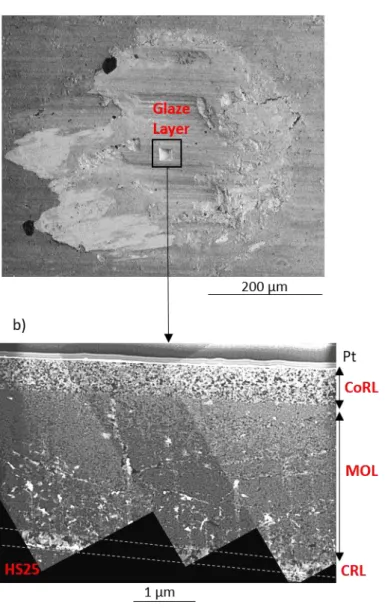
A TEM lamella was extracted from the glaze layer interface (N=200 000). The lamella was localized at the center of the wear track where the glaze layer entirely covers the interface, as presented in Fig. 8 a).
Fig. 8 b) is an assembly of TEM bright field micrographs of the lamella where the effective area is around 20 µm3. The lamella presents different layers as seen in Fig. 5, namely the cobalt-rich layer (CoRL), the mixed oxide layer (MOL), a small portion of the chromium-rich layer (CRL) and the bulk material (HS25). The transmission microscope reveals that the cobalt-rich layer (effective glaze layer) has a thickness of about 570 nm. The cobalt-rich layer is also homogeneous with a quite constant grain size, evaluated to be between 40 and 50 nm, which thus confirms the nanocrystalline structure of the effective glaze layer [8,9,27]. The mixed oxide layer is more heterogeneous with a mixture of different grains and with some porosities displaying white color.
14
Fig. 8: a) Location of the TEM lamella extracted in the wear track for N ≥ NGL; b) TEM observation of the lamella in bright
field. CoRL refers to the Cobalt-Rich Layer, MOL to the Mixed Oxide Layer and CRL to the Chromium-Rich Layer.
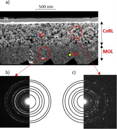
Fig. 9 a) presents a high resolution TEM bright field micrograph of the cobalt-rich layer (CoRL) and the mixed oxide layer (MOL). EDX measurements, presented in Table 4, were performed in both layers and confirm the higher cobalt content in the cobalt-rich layer compared to chromium. Figs. 9 b) and c) display the diffraction patterns performed in the mixed oxide layer and the cobalt-rich layer, respectively. Both diffraction patterns are circular, showing that they are polycrystalline and they do not present preferential orientation. The indexation of the rings is quite difficult since all the oxides of interest have radii close to each other. However, it seems that there is, in both patterns, Co3O4 oxides or spinels (Ni,Cr)xCo3-xO4. The
main difference between the mixed oxide layer and the cobalt-rich layer is the grain size of the oxides. The diffraction pattern of the oxide particle layer (Fig. 9 b)) presents continuous rings compared to that of the cobalt-rich layer (Fig. 9 c)) where the rings are an accumulation of isolated diffraction spots. Hence, the grain size is smaller in the mixed oxide layer than in the cobalt-rich layer.
15
Fig. 9: a) TEM observation of the tribolayer (cobalt-rich layer and mixed oxide layer); b) diffraction pattern performed in selected area of the mixed oxide layer; c) corresponding diffraction pattern performed in the cobalt-rich layer. CoRL
refers to the Cobalt-Rich Layer and MOL to the Mixed Oxide Layer
Table 4: Chemical composition of the cobalt-rich layer (#1) and the mixed oxide layer (#2) in at. % measured by EDX on the TEM lamella. CoRL refers to the Cobalt-Rich Layer and MOL to the Mixed Oxide Layer
Zone O Co Cr Ni W Mn Fe Co/Cr
#1 CoRL 67.7 ± 1.7 24.08 ± 0.3 2.72 ± 0.3 2.04 ± 0.2 0.45 ± 0.0 0.21 ± 0.0 0.31 ± 0.1 8.85 #2 MOL 66.5 ± 1.8 14.77 ± 0.8 8.91 ±0.9 2.74 ± 0.3 1.86 ± 0.1 0.85 ± 0.3 0.79 ± 0.0 1.66
Fig. 10 presents a high resolution TEM micrograph of the cobalt-rich layer near the fretted surface. The CoRL presents an amorphous band near the fretted interface as proved by the FFT pattern (B) which displays a bright halo with no diffraction spots. On the contrary, below the first 20 nm, the cobalt-rich layer presents a FFT pattern with spots as seen in (A). Some amorphous zones have been observed by other authors on cobalt-based glaze layers [11], especially near the fretted interface. In the present study, the lamella was not thin enough to perform high resolution TEM observations except along the first 100 nm and it is then impossible to adjudicate on the presence, or not, of amorphous zones in the entire cobalt-rich layer. Finally, it is interesting to notice that it is highly possible that the XPS measurements were made in an amorphous zone since the depth of analysis is around 5 nm.
16
Fig. 10: High resolution TEM observation of the fretted interface (the yellow lines indicate the interface between the protective Pt layer and the CoRL). The FFT (B) indicates the presence of an amorphous zone in the first 20 nm of the
CoRL whereas the FFT (A) indicates that below, the CoRL is crystalline. CoRL refers to the Cobalt-Rich Layer
5. Synthesis
5.1. Oxidation mechanism without fretting loading
The HS25 alloy was designed to resist hot corrosion by the presence of a high content of chromium (and manganese in fewer proportions) in solid solution. As classically observed for chromia-forming alloys, the present experiments show that after 2 h of hot corrosion at 575°C, the surface is covered by a thin oxide layer (Fig. 2 b)) of about 200 nm, which prevent further oxidation. The XPS measurements, in Fig. 7, reveal that the oxide layer is richer in chromium than the bulk metal, displaying a preferential oxidation of chromium elements compared with cobalt elements. The same results were found for manganese but were not presented here. This is consistent with the thermodynamic stability of the oxides where the oxygen affinity of chromium and manganese is higher than that of cobalt, nickel and iron [22]. Buscail et al [18] have shown on a cobalt-based alloy similar to the Haynes 25 (Phynox) that the oxide layer formed during hot corrosion at 800°C for 2 h is mainly composed of Cr2O3 and Mn1.5Cr1.5O4. It is then highly possible that these
oxides were formed at the interface. Moreover, the survey XPS spectra presented in Fig. 6 and previous Raman analyses [7] show that there are some traces of other elements such as tungsten, cobalt and nickel.
17
Hence, the oxide layer is made of mixed oxides with a higher content in chromium and manganese. The alloy structure not subjected to fretting is illustrated in Fig. 11 a) for N = 0.
5.2. Tribo-oxidation kinetics
The morphology of the oxide layer subjected to tribological testing is quite different from that obtained in static oxidation. Fig. 2 b) shows that the thickness of the oxide layer after 2 h of static oxidation at 575°C is much thinner than the tribo-oxide layer formed after 100 s of fretting-wear at 575°C (200 nm against 2-3 µm). According to Stott [3], there is an increase of the oxidation reaction during the tribo-oxidation process due to the plastic deformations and the frictional flash temperatures. First, the plastic deformations induce some cracks, grain size reduction (and then an increase in the grain boundaries) or porosities which promote the diffusion of oxygen inside the bulk material [22]. Hence, a tribologically-assisted oxidation process is activated due to the mechanical loading of the fretted interface.
Fig. 11: Schematic illustration of the fretting wear interface of the studied HS25/alumina tribosystem generated at 575°C. CoRL refers to the Cobalt-Rich Layer, MOL to the Mixed Oxide Layer and CRL to the Chromium-Rich Layer
Fig. 11 b) displays a schematic illustration of the fretting wear interface before the creation of the glaze layer (N < NGL). Before the glaze layer formation, wear increases linearly with the number of fretting cycles so
that the energetic wear coefficient is positive (Fig. 4) [19]. The friction coefficient is decreasing and the wear volume is increasing, both towards a stable value only achieved when the glaze layer protection is effective (NGL = 20 000). Hence, there is no glaze layer at 5 000 cycles, but a powdered debris layer. The oxidized third
body is composed of two layers: the mixed oxide layer (MOL) and the deep chromium-rich layer (CRL). According to Fig. 5 a.3), the mixed oxide layer is oxidized and presents an enhanced chromium depletion from the chromium-rich layer to the worn surface. This depletion has not been well understood yet. However, it may be a sign of migration of chromium through the mixed oxide layer towards the interface (cationic diffusion). Moreover, the XPS measurements, illustrated in Fig. 7 c), indicate an accumulation of chromium in the first 5 nm of the surface. Hence, the chromium possibly migrates outward and is oxidized. The Co/Cr ratio calculated from XPS results in Fig. 7 c), indicates that there is slightly more cobalt than
18
chromium elements at that stage of the wear process compared to static oxidation, thus confirming an enhanced diffusion process of metallic element. However, the oxidation process should be the same, namely a preferential oxidation of chromium.
Fig. 11 c) illustrates the fretted interface at 200 000 cycles, when the glaze layer is effective and when both friction coefficient and wear volume are stable. The energetic wear coefficient is then equal to zero (Fig. 4). There is the presence of an additional top layer, the cobalt-rich layer (CoRL), which covers the mixed oxide layer (MOL) and prevents the contact from further wear. Since the cobalt-rich layer appears when the wear evolution is stable, it is stated that the CoRL is the effective glaze layer after which there is no more additional wear. According to Fig. 5 b.3), the oxygen content is much higher at 200 000 cycles than at 5 000 cycles, which underlines the beneficial effect of the mechanical loading on the oxygen diffusion. The thickness of the entire tribolayer is around 6 µm. EDX, TEM and XPS observations (Fig. 5 b.3), Fig. 7 b) and Table 4) show the large amount of cobalt compared to chromium in the cobalt-rich layer and the diffraction pattern in Fig. 9 indicates a predominance of Co3O4 (or spinels) oxides. Moreover, the mixed oxide layer
presents a stable Co/Cr ratio with a slight chromium depletion, according to the EDX measurements (Fig. 5 b.3)). TEM (Fig. 9 and Table 4) and XPS analysis (Fig. 7 c)) confirm on the contrary a cobalt depletion at the extreme surface. It is not clear if the main diffusion process is due to an anionic or cationic mechanism. Stott showed in [28] that the oxidized sub-layer (called MOL in our study) is due to internal diffusion by a facilitating access of oxygen into the alloy. His premise is corroborated by the formation of the top layer (CoRL) before the sub-layer (MOL). In our work, there is no clear evidence of anionic diffusion since the CoRL is built after the MOL sub-layer. However, the presence of the CRL indicates an anionic diffusion which may not be the driving process since cationic diffusion is more rapid than anionic diffusion for this kind of chemical elements (transition elements) [23]. Hence, it is highly possible that both of the mechanisms are involved in the oxidation process of the mixed oxide layer. However, the cobalt depletion observed just below the glaze layer may be induced by a cationic diffusion of cobalt in the effective glaze layer. Indeed, cobalt elements have good auto-diffusion properties and are more willing to diffuse in their oxides than chromium elements [7].
5.3. Mechanism of the glaze layer formation
Experiments clearly indicate that the surface chemical composition is changing from a cobalt depletion before the effective glaze layer formation to a chromium depletion when the effective glaze layer is formed. This chemical displacement has never been observed so clearly before and it is related to the effective glaze layer formation. Indeed, it seems that chromium needs to be evacuated to form the cobalt-rich effective glaze layer through a debris sintering process. This observation is corroborated by a previous study [7] showing that pure cobalt is able to form a glaze layer whereas pure chromium is not able to. It was attributed to the higher auto-diffusion coefficient of cobalt in Co3O4 than that of chromium in Cr2O3.
19
Fig. 12: Evolution of the third body from the oxide debris layer to the protective lubricant glaze layer
(a) Before fretting solicitation, a transient oxide layer is created at the interface, probably similar to that formed during hot corrosion, enriched in chromium and manganese.
(b) When the sliding process begins, the passive layer is rapidly ejected by the mechanical action of the hard alumina counterface and some ceramic/metal interactions take place. Hence, the friction coefficient is high. Then, the oxygen access is enhanced by the wear track extension, the sharp reduction of the contact pressure and by the generation of cracks or new grain boundaries. The diffusion of oxygen in the subsurface may lead to the formation of a mixed oxide layer as well as the formation of a steady-state chromium-rich layer at the substrate interface. At the same time, the oxide layer is continuously ejected by the abrasive effect of the hard alumina [5,19], leading to a continuous process of transient oxidation. Hence, chromium elements seem to diffuse outward and become oxidized, leading to a chromium-depletion in the mixed oxide layer and a chromium enrichment at the surface. This diffusion process is promoted by the grain refinement and/or the plastic deformations. The process goes on until there is no more chromium available to be oxidized. (c) Following the quasi complete chromium-depletion in the mixed oxide layer, cobalt starts to be
oxidized and thus, cobalt oxides particles are detached from the interface by the abrasive alumina counterpart. Cobalt diffuses easily in its oxides compared to chromium, and oxide debris start to be welded to each other, thus changing the rheology of the debris-bed layer. The oxide debris is more adherent and undergoes further comminution, fracture and welding, leading to a complete sintering process between nanocrystalline particles (with diameters around 40-50 nm). The protective third body is formed and is therefore made of a layered structure.
20
(d) When the cobalt-rich effective glaze layer is formed, the friction coefficient and the wear volume are stabilized. Moreover, there is no metallic cobalt left in the effective glaze layer due to the complete oxidation of particles during the comminution process. The mixed oxide layer is very thick (around 6 µm) but the involved diffusion mechanism is still unclear. The diffraction pattern in the mixed oxide layer shows the presence Co3O4 oxides or spinels (Ni, Cr)xCo3-xO4. The adhesion of the glaze layer to
the oxidized substrate might be due to the welding of Co3O4 grains between the cobalt-rich layer
(effective glaze layer) and the mixed oxide layer.
Finally, it is interesting to notice that according to this glaze layer formation scenario, chromium tends to delay the glaze layer formation and thus promotes severe wear. However, for static oxidation, chromium is a good alloying element to protect the interface from further corrosion by creating a stable and thin oxide layer.
5.4. Tribological properties of the glaze layer
The effective glaze layer (CoRL) displays a thickness of about 570 nm with a mean grain size of 45 nm. The grain size is quite large compared to the literature where it is around 5 – 20 nm [8–10,29] for similar glaze layers. However, the mechanical loading is more severe in this study which induces a more severe shear stress gradient. Rupert et al [12] showed that a grain growth can occur in such tribological structures due to the very high shear stress imposed to the material. Moreover, the thinner grains below the effective glaze layer as shown in Fig. 9 a) corroborates a grain growth process near the fretted interface. Hence, this suggests that the effective glaze layer is softer than the mixed oxide layer. Further experiments such as indentation tests need to be performed to confirm this point.
Conclusion
This research focused on the high-temperature fretting wear response of a cobalt-based alloy containing chromium, tungsten and nickel. A lubricant and protective glaze layer is formed when temperature is higher than 400°C and it induces a reduction of the wear volume and the friction coefficient. Cross-section imaging and chemical analyses outline the following points:
The glaze layer is not homogeneous as previously depicted in the literature [9,15] but rather composed of a layered structure with three distinct layers: a deep chromium-rich layer, a mixed oxide layer and a top cobalt-rich layer. Interrupted fretting tests reveal that the effective glaze layer, leading to the no-wear regime, is the 570 nm cobalt-rich layer.
The effective glaze layer is formed from the oxide debris generated at the beginning of the fretting test. This layer is nanocrystalline and the grains are randomly oriented. Moreover, due to the tribological process, the presence of an amorphous band is detected at the surface (thickness of 20 nm). The initial stoichiometry of the alloying elements is not respected and a chemical diffusion process may happen during the fretting process.
It is argued that cobalt has better sintering properties than chromium. All the chromium elements present at the interface need to be consumed by oxidation and abrasion to start the formation and the sintering of cobalt oxides. Finally, the formation kinetics of the glaze layer is driven by the chromium depletion process.
21 References
[1] S. Descartes, Y. Berthier, Rheology and flows of solid third bodies: Background and application to an MoS1.6 coating, Wear. 252 (2002) 546–556. doi:10.1016/S0043-1648(02)00008-X.
[2] N. Fillot, I. Iordanoff, Y. Berthier, Modelling third body flows with a discrete element method-a tool for understanding wear with adhesive particles, Tribol. Int. 40 (2007) 973–981. doi:10.1016/j.triboint.2006.02.056.
[3] F.H. Stott, High-temperature sliding wear of metals, Tribol. Int. 35 (2002) 489–495. doi:10.1016/S0301-679X(02)00041-5.
[4] J. Jiang, F.H. Stott, M.M. Stack, The role of triboparticulates in dry sliding wear, Tribol. Int. 31 (1998) 245–256. doi:10.1016/S0301-679X(98)00027-9.
[5] A. Dreano, S. Fouvry, G. Guillonneau, A combined friction energy and tribo-oxidation formulation to describe the high temperature fretting wear response of a cobalt-based alloy, Wear. 426–427 (2019) 712–724. doi:10.1016/j.wear.2019.01.023.
[6] H. Kato, K. Komai, Tribofilm formation and mild wear by tribo-sintering of nanometer-sized oxide particles on rubbing steel surfaces, Wear. 262 (2007) 36–41. doi:10.1016/j.wear.2006.03.046.
[7] A. Viat, A. Dreano, S. Fouvry, M.-I. De Barros Bouchet, J.-F. Henne, Fretting wear of pure cobalt chromium and nickel to identify the distinct roles of HS25 alloying elements in high temperature glaze layer formation, Wear. 376–377 (2017) 1043–1054. doi:10.1016/j.wear.2017.01.049.
[8] C. Rynio, H. Hattendorf, J. Klöwer, G. Eggeler, On the physical nature of tribolayers and wear debris after sliding wear in a superalloy/steel tribosystem at 25 and 300°C, Wear. 317 (2014) 26–38. doi:10.1016/j.wear.2014.04.022.
[9] A. Viat, M.-I. De Barros Bouchet, B. Vacher, T. Le Mogne, S. Fouvry, J.-F. Henne, Nanocrystalline glaze layer in ceramic-metallic interface under fretting wear, Surf. Coatings Technol. 308 (2016) 307–315. doi:10.1016/j.surfcoat.2016.07.100.
[10] I.A. Inman, S. Datta, H.L. Du, J.S. Burnell-Gray, Q. Luo, Microscopy of glazed layers formed during high temperature sliding wear at 750°C, Wear. 254 (2003) 461–467. doi:10.1016/S0043-1648(03)00134-0. [11] T.W. Scharf, S. V. Prasad, P.G. Kotula, J.R. Michael, C. V. Robino, Elevated temperature tribology of
cobalt and tantalum-based alloys, Wear. 330–331 (2015) 199–208. doi:10.1016/j.wear.2014.12.051. [12] T.J. Rupert, C.A. Schuh, Sliding wear of nanocrystalline Ni-W: Structural evolution and the apparent
breakdown of Archard scaling, Acta Mater. 58 (2010) 4137–4148. doi:10.1016/j.actamat.2010.04.005. [13] M.A. Meyers, A. Mishra, D.J. Benson, Mechanical properties of nanocrystalline materials, Prog.
Mater. Sci. 51 (2006) 427–556. doi:10.1016/j.pmatsci.2005.08.003.
[14] C. Rynio, H. Hattendorf, J. Klöwer, G. Eggeler, The evolution of tribolayers during high temperature sliding wear, Wear. 315 (2014) 1–10. doi:10.1016/j.wear.2014.03.007.
[15] A. Viat, G. Guillonneau, S. Fouvry, G. Kermouche, S. Sao Joao, J. Wehrs, J. Michler, J.-F. Henne, Brittle to ductile transition of tribomaterial in relation to wear response at high temperatures, Wear. 392– 393 (2017) 60–68. doi:10.1016/j.wear.2017.09.015.
[16] A. Viat, S. Fouvry, M.-I. De Barros Bouchet, L. Pin, Influence of carbon-based solid lubricant on fretting wear response for alumina-based ceramics versus cobalt superalloy contact, Surf. Coatings Technol.
22 284 (2015) 327–333. doi:10.1016/j.surfcoat.2015.07.043.
[17] A. Korashy, H. Attia, V. Thomson, S. Oskooei, Characterization of fretting wear of cobalt-based superalloys at high temperature for aero-engine combustor components, Wear. 330 (2015) 327–337. doi:10.1016/j.wear.2014.11.027.
[18] H. Buscail, F. Riffard, C. Issartel, S. Perrier, Oxidation mechanism of cobalt based alloy at high temperatures (800–1100°C), Corros. Eng. Sci. Technol. 47 (2012) 404–410. doi:10.1179/1743278212y.0000000007.
[19] A. Dreano, S. Fouvry, G. Guillonneau, A tribo-oxidation abrasive wear model to quantify the wear rate of a cobalt-based alloy subjected to fretting in low-to-medium temperature conditions, Tribol. Int. 125 (2018) 128–140. doi:10.1016/j.triboint.2018.04.032.
[20] S. Fouvry, P. Arnaud, A. Mignot, P. Neubauer, Contact size, frequency and cyclic normal force effects on Ti–6Al–4V fretting wear processes: An approach combining friction power and contact oxygenation, Tribol. Int. 113 (2017) 460–473. doi:10.1016/j.triboint.2016.12.049.
[21] A.R. Warmuth, P.H. Shipway, W. Sun, Fretting wear mapping: the influence of contact geometry and frequency on debris formation and ejection for a steel-on-steel pair, Proc. R. Soc. A Math. Phys. Eng. Sci. 471 (2015) 20140291–20140291. doi:10.1098/rspa.2014.0291.
[22] T. Richardson, B. Cottis, D. Scantlebury, R. Lindsay, S.B. Lyon, M. Graham, Shreir’s Corrosion - Volume I, 2010. doi:10.1016/C2009-1-28357-2.
[23] P.K. Kofstad, A.Z. Hed, High-Temperature Oxidation of Co-10 w/o Cr Alloys, J. Electrochem. Soc. 116 (1969) 224–229.
[24] F.H. Stott, D.S. Lin, G.C. Wood, The structure and mechanism of formation of the ‘glaze’ oxide layers produced on nickel-based alloys during wear at high temperatures, Corros. Sci. 13 (1973) 449–469. doi:10.1016/0010-938X(73)90030-9.
[25] C. Mary, S. Fouvry, J.M. Martin, B. Bonnet, Pressure and temperature effects on Fretting Wear damage of a Cu-Ni-In plasma coating versus Ti17 titanium alloy contact, Wear. 272 (2011) 18–37. doi:10.1016/j.wear.2011.06.008.
[26] C. Mary, T. Le Mogne, B. Beaugiraud, B. Vacher, J.-M. Martin, S. Fouvry, Tribochemistry of a Ti Alloy Under Fretting in Air: Evidence of Titanium Nitride Formation, Tribol. Lett. 34 (2009) 211–222. doi:10.1007/s11249-009-9426-6.
[27] H.L. Du, P.K. Datta, I.A. Inman, R. Geurts, C. Kübel, Microscopy of wear affected surface produced during sliding of Nimonic 80A against Stellite 6 at 20°C, Mater. Sci. Eng. A. 357 (2003) 412–422. doi:10.1016/S0921-5093(03)00258-2.
[28] F.H. Stott, D.S. Lin, The structure and mechanism of formation of the “glaze oxide layers” produced on nickel-based alloy during wear at high temperatures, Corros. Sci. 13 (1973) 449–469.
[29] L. Xin, Z.H. Wang, J. Li, Y. Lu, T. Shoji, Microstructural characterization of subsurface caused by fretting wear of Inconel 690TT alloy, Mater. Charact. 115 (2016) 32–38. doi:10.1016/j.matchar.2016.03.010.
23 Aknowledgments
This work was supported by the LABEX MANUTECH-SISE (ANR-10- LABX-0075) of Université de Lyon, within the program “Investissements d'Avenir” (ANR-11-IDEX-0007) operated by the French National Research Agency (ANR) and by l'EQUIPEX MANUTECH-USD (ANR-10-EQPX-36-01). Authors would like to convey their gratitude to Nicholas Blanchard for his TEM expertise and Prof. Pierre Guiraldenq for the fruitful discussions on diffusion.


![[PDF] Cours Modèles de conception UML](data:image/gif;base64,R0lGODlhAQABAIAAAP///wAAACH5BAEAAAAALAAAAAABAAEAAAICRAEAOw==)