HAL Id: hal-02379342
https://hal.archives-ouvertes.fr/hal-02379342
Submitted on 25 Nov 2019
HAL is a multi-disciplinary open access
archive for the deposit and dissemination of sci-entific research documents, whether they are pub-lished or not. The documents may come from teaching and research institutions in France or abroad, or from public or private research centers.
L’archive ouverte pluridisciplinaire HAL, est destinée au dépôt et à la diffusion de documents scientifiques de niveau recherche, publiés ou non, émanant des établissements d’enseignement et de recherche français ou étrangers, des laboratoires publics ou privés.
Extension of SIMO wideband channel sounder for UWB
propagation experiment
Patrice Pajusco, Pascal Pagani
To cite this version:
Patrice Pajusco, Pascal Pagani. Extension of SIMO wideband channel sounder for UWB propagation experiment. IEEE Conference on ultra wideband systems and technologies, Nov 2003, Reston, United States. pp.250 - 254, �10.1109/UWBST.2003.1267842�. �hal-02379342�
EXTENSION OF SIMO WIDEBAND CHANNEL SOUNDER
FOR UWB PROPAGATION EXPERIMENT
Patrice Pajusco, Pascal Pagani
France Telecom R&D/DMR/OIP, 6 av. des Usines BP 382, F-90007 Belfort Cedex, France e-mail: { patrice.pajusco; pascal.pagani }@francetelecom.com
Abstract---Good knowledge of transmission
channel properties is necessary to study the performances of future UWB systems. Thus, efficient equipment is required to characterize and model the UWB propagation channel. This paper proposes a basic idea to convert a SIMO wideband channel sounder into an UWB channel sounder. These minor changes were applied to the France Telecom R&D channel sounder. The modified equipment enables real time measurement in the 3.1 - 10.6 GHz frequency band with more than 1 GHz bandwidth.
Index Terms- Channel sounding, radio
propagation, ultra-wide bandwidth. 1. INTRODUCTION
UWB techniques have been lmown in radar application for several decades. Nevertheless, the use of this technology in radio communication is relatively new and very promising. The FCC frequency band is defined between 3.1 and 10.6 GHz. To exploit all the benefits of the UWB concept, it seems interesting to use the whole allocated frequency band. However, it is difficult to generate such narrow pulses. Moreover, the temporal diversity seems to decrease above 1 GHz bandwidth [l]. This probably explains the emergence of multi-band solutions with about 1 GHz bandwidth.
Future UWB telecommunication systems will be used in mobile indoor configurations. The effect of people or moving obstacles on the channel impulse response will be very important. Thus, it is necessary to characterize the short-term variability of the propagation channel in UWB radio links.
This paper aims to present simple modifications which enable to extend a SIMO wideband channel sounder to an efficient UWB channel sounder. Section 2 will review usual methods to measure the UWB propagation charme!. Then, the basic structure of our SIMO channel sounder will be introduced (section 3). Next section will present hardware modification and post processing. We will conclude by presenting some measurement results to demonstrate the first capabilities ofthis new equipment (section 5).
2. UWB SOUNDING TECHNIQUES Currently, most of UWB propagation experiments use a Vector Network Analyser ([l], [2], [3], [4], [5]). The frequency sounding technique is widely known, due to its ease and advantages of implementation. Firstly, there is no limit on the frequency bandwidth. The only limits are usually imposed by antenna characteristics. Secondly, the dynamic range of measurement is good enough if Low Noise Amplifiers are used. For instance, very precise analysis can be performed using a virtual planar array. Nevertheless, the duration of the frequency sampling and the data transfer is quite long, lasting several seconds for each measurement point. During the acquisition time, the propagation channel necds to be constant. As a consequence, this approach is limited to the characterization of static environments. The effect of moving people cannot be investigated with this method.
For dynamic charme! measurements, the first solution is to use a UWB chip in the transmitter equipment to actually emit UWB pulses, with a spectral bandwidth above 1.5 GHz. The channel impulse response is then estimated by sampling the received signal with a Digital Sampling Oscilloscope {[6J, [7]). This method is quite simple to implement. However, the transmitted wavefonn is imposed and the dynamic range of measurement is limited (high level of noise and low level of power).
The second solution to sound dynamic channels consists in using a wideband channel sounder and measuring several adjacent partial bands. This principle was investigated and successfully implemented in [8]. The main problems are the fast generation of various oscillators and the synchronization of the signais. The
mentioned equipment was able to measure a propagation channel every 300 µs with 600 MHz bandwidth.
In indoor configuration, the speed of moving tenninals is about 2 mis. Considering the worst case, a maximum frequency of 10.6 GHz and a mobile terminal, the maximum Doppler shift is v / À = 70 Hz. This maximum Doppler shift increases to 2.v I À.= 140 Hz if one considers mobile scatterers, taking into account the paths with one reflection as significant paths. Thus, to
characterize time variant UWB propagation channels, the equipment bas to sample the channel every 3.5 ms.
Considering the UWB multi-band concept with a bandwidth between 500 and 700 MHz, our brief overview shows that there is only a few equipments really suited for such characterization. Moreover, there is no equipment available to probe greater bandwidths in order to study the lirnit of the multi-band channel size.
3. PRINCIPLE OF SIMO CHANNEL SOUNDER The basic idea to perforrn dynarnic UWB channel
measurements is to measure several adjacent partial bands using a wideband channel sounder. The main problems to overcome are the fast switching of the partial bands with full synchronization with the transmitted sequence; the calibration of each sub-band (with respect to phase, amplitude and delay); the high dynarnic range; and the real time constraint.
This problem is quite sirnilar to SIMO wideband characterization. Thus, we studied the SIMO sounding structure to reuse most of the elements for UWB characterization. For a better understanding, this section reviews the general structure of our SIMO wideband channel sounder. More details can be found in [9].
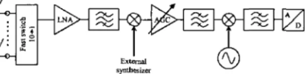
The receiver (Fig. 1) can measure up to 10 inputs. To repeat measurements as fast as possible, antennas are switched every other sequence. The first sequence is used for data sampling and the following time slot for antenna switching. This principle can be applied because the transmitted signal is periodic. Practically, a fast switch is used to select one of the incoming signals. The signal is then amplified using a wideband LNA (3-18 GHz) and pass-band filtered. The filter characteristics depend on the analysed frequency band. The output frequency of the first down-converter is 1.5 GHz. The following 60 dB attenuators are used to compensate for the power variations of the received signal (Automatic Gain Contrai). The AGC is performed before the measurement of the multiple inputs. Thus, the AGC duration Iimits the maximum measurement repetition rate. In a usual configuration with 10 inputs,
the maximum rate is about 830 Hz. The second down converter is centered at 250 MHz. The output signal is then sampled by a 1 Gsample/s digitaliser.
On the transrnitter side, an arbitrary waveform generator (1 Gsample/s) produces a real periodic sequence which occupies a maximal bandwidth of 250 MHz centered around an Intermediate Frequency of 250 MHz. This signal is then up-converted around the canier frequency. It can be noticed that transrnitter and receiver parts use the same lntermediate Frequency.
Fig. 1. Block diagram of the receiver.
Thus, the frequency of the local oscillator is the same in bath the transrnitter and receiver. Ali synthesizers are synchronized on a 10 MHz reference rubidium.
The calibration is very important in SIMO configuration. Each channel needs to be calibrated in amplitude, phase and de1ay. The principle is to connect the transrnitted signal directly to the receiver. A calibrated RF coupler is used to split the transmitted signal through the different inputs. This wideband reference measurement takes into account all the characteristics of the inputs: absolute gain and delay, phase, gain variation in the sounding band... This reference and the characteristics of the coupler are used during the channel impulse estimation (Wiener inversion). This process naturally calibrates each input.
4. EXTENSION TO UWB 4.1. Principle
In order to convert our SIMO channel sounder into an UWB channel sounder, we exploited the duality between multiple input measurements and multi-band measurements. The basic idea of this concept is to use the multiple input switching module for the synchronous switching of the carrier frequencies of all partial bands to be measured.
The practical realization of this concept is presented in Fig. 2. As we can see, the input connector is now directly connected to the LNA, while the Fast Switching Module sequentially feeds the mixer of the first down converter stage with one of the 10 oscillator signais (F1 to F10) in tum. These signais are generated by external synthesizers and tuned so that the receiver actually sweeps the desired partial bands. This configuration allows for single input, multiple band measurements with up to 10 partial bands of 250 MHz each, hence UWB measurements are theoretically possible with a bandwidth up to 2.5 GHz.
On account of its development concept, this extended channel sounder naturally fulfils most of the required criteria for real-time UWB channel measurement. Regarding the calibration of each partial band in terms of phase, amplitude and delay, the same
Ext.cmal
synthesiz{T.> the �miner up-convener
Fig. 2. Block diagram of the modified receiver for the extension to UWB.
procedure as in the SIMO configuration remains valid,
except that there is no more use of a coupler.
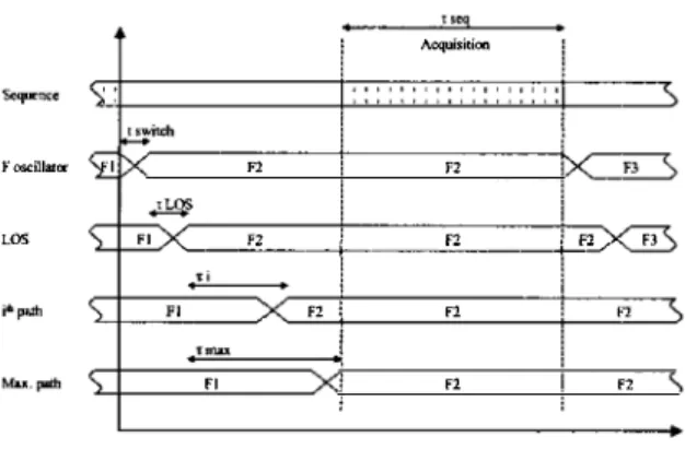
Conceming the fast switching of the partial bands, no software modification is needed. First, the frequency switch is still synchronized with the transmitted sequence period. Second, the sweep tirne through all partial bands rnay be reduced down to 1.2 ms, allowing the rneasurement of the tirne variations of the channel with a Doppler shift up to 416 Hz. Third, acquisition is performed every other sequence, leaving one sequence for frequency switching. Undoubtedly, the frequency switching case is more critical than the input switching case, as the ernitted signal is no longer periodic. Thus, it is necessary to wait the end of the transient statc bcforc sampling a new sequence. However, given the length of the emitted sequence (2.048 µs), the maximum path lengths in indoor configurations (about 150 m) and the duration of the actual frequency switch (!switch = 100 ns),
the condition is met at the start of the sampled sequence. This configuration remains valid as long as the following inequality is fulfilled:
f switch + I LOS + '( max < f seq (1) where tru,rch is the switch duration, fws is the absolute
delay of the LOS path, z:iuu is the maximum recordable
delay with respect to the LOS arrivai time and t,eq is the duration of the sequence. A graphical representation of this concept is given in Fig. 3.
4.2. UWB specific issues
In addition to the main modification regarding the use of the Fast Switching module, further changes have been perfonned on our SIMO channel sounder in order to address some UWB specific issues.
a)Filtering: in the SIMO channel sounder, the filter
preceding the first down-converter stage in the receiver (Fig. 1) was only a few hundreds of MHz wide to reject
undesirable signals and reduce the noise level. The same type offiltering is perfonned in the emitter. In the UWB configuration, however, the sounded frequency band
FoscilllllŒ LOS Acquisition F.l F.l '---'-'"'---' --�--..,_'2:__ __ .j....éF=-.,,1 F3 Fl J F1 F1 FI
"
F2Fig. 3. Chrono gram of the switching and acquisition phases at the receiver.
IF
Fig. 4. Sub-band sweep and filtering.
needs to be filtered by one single pass-band filter, in order to avoid unnecessary filter switching. In the current version of our SlMO channel sounder, the lntermediate Frequency of this stage is 1.5 GHz. The maximum filter width is hence limited to 1.5 GHz, for the unwanted Local Oscillator signal to stay outside the filter limits during the whole partial band sweep. This situation is depicted in Fig. 4.
In order to increase the size of the measurable bandwidth, another configuration is available in the SIMO channel sounder, with an IF at 5.5 GHz. Using this configuration, it would be possible to enlarge the filter bandwidth to the lirnit of 2.5 GHz imposed by the number of available partial bands. The only condition in this mode of measurement would be to avoid the IF frequency of 5.5 GHz in the scanned band.
In its current state, our UWB channel sounder has been equipped with filter bandwidths up to 1.2 GHz, which is thus the limit of the currently measurable bandwidth.
b) Synchronisation: Unlike the SIMO channel
sounding case, UWB measurements using the sweeping method necessitate a constant modification of the emitted signal central frequency. For this reason, the frequency switch perfonned at the receiver and at the emitter need to be perfectly synchronised. To solve this problem, we chose to use the same Local Oscillator signal to feed both the receiver down-converter and the
emitter up-converter stages. This was possible sinceJhe receiver and the emitter use the same Intermediate Frequency. One drawback of this solution is that the emitter and the receiver parts need to be cable connected. However, in most indoor configurations, this connection is realizable using a cable of acceptable length. As an advantage, this solution allows one to use only one set of external synthesizers, which considerabl:i,
reduces the global cost of the equipment.
c) Partial bands fine calibration: as presented
earlier, the back-to-back measurement procedure inherited from the SIMO channel sounder permits a first calibration of each partial band. This procedure naturally adjusts the relative delay experienced for each partial band. One should note, however, that 1 O extemal synthesizers are used in the UWB configuration. Despite their common 10 MHz reference, each of these devices undergoes an independent phase drift. To compensate for this unavoidable drift, a partial band fine calibration is performed after the measurement by post-processing. For this purpose, a given frequency overlap is required between two adjacent partial bands, over which the amplitude and phase of the recorded spectrums is compared and adjusted using a best fit criterion. In the current configuration, the best results are obtained using
partial band overlaps of about 40 MHz, resulting in a reduction of the theoretical maximum measurable bandwidth from 2.5 GHz to 2.14 GHz.
5. EXPERIMENTAL V ALIDA TION The modifications presented above have been applied to our SIMO channel sounder for its extension to real-time UWB measurements. The emitter up converter and receiver down-converter stages have been equipped with filters with bandwidths of about 1 GHz. To sweep the desired frequency band, 5 external synthesizers have been connected to the Fast Switching module and tuned to the central frequencies of 5 partial bands.
In terms of sounding performance, our test results showed an Impulse Response dynarnic of 40 dB. In this
configuration with 5 partial bands, the minimum measurement repetition time is about l ms and the actual measurement duration is 20.5 µs. With its 256 MB memory, the acquisition card is able to sound the time variant UWB channel for a duration of 80 s in standard conditions (bandwidth of I GHz and observable Doppler shift of 150 Hz).
For the first experimental results, the UWB channel sounder was parameterized to sound the 5 GHz - 6 GHz frequency band. Measurements were performed in a
50 100 150
Delay {ns) 200
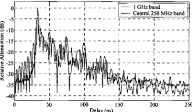
Fig. 5. Power Delay Profiles in a static environment.
250
large room representative of the indoor office environment, using an omni-directional antenna.
Fig. 5 shows the performance of the UWB sounder in a static environment, in the LOS configuration. Two Power Delay Profiles are represented, for the global l GHz band (black line) and the central 250 MHz band (grey line). The Impulse Responses have been averaged over 100 measurements for the purpose of noise reduction. The benefits of UWB in terms of resolution of the multipath components are clearly visible. In the l GHz band case, several multipath components are observable, while a few only are resolvable in the 250 MHz partial band case. The side lobes on the left hand side of the second curve are due to the rectangular window used in this graph for a finer resolution.
Results obtained in a dynamic situation are represented in Fig. 6 and 7. In this experiment, we used a mobile receiving antenna held by a moving person. Along the trajectory, both LOS and NLOS situations were encountered.
Fig. 6 presents a time-variant Power Delay Profile, showing a 12.5 s record of the signal obtained at the moving receiving antenna. For case of interpretation, the excess delay has been converted in excess path in meters. In the first part of the trajectory (between t = 0 s and t = 7 s), the person is moving towards the emitter antenna, reducing its relative distance from 6 m to 2 m. Hence, one can observe a main path with increasing power (a). In the second part of the trajectory, (between t = 7 s and t "".11 s), the person is moving away from the emitter antenna, partially obstructing the line of sight. This explains the shadowing experienced by the shortest path (b). In this part of the curve, three other main paths are observable, one with increasing length (c) and two with decreasing lengths (d, e). These two last paths might correspond to echoes transmitted via a reflection on a wall opposite to the emitter location.
6
î
s -5 !. :li JOl
12 14 16 Hl 0 l 4 6 8 lO Il Timc(s)Fig. 6. Time variant Power Delay Profile in a dynamic indoor environment.
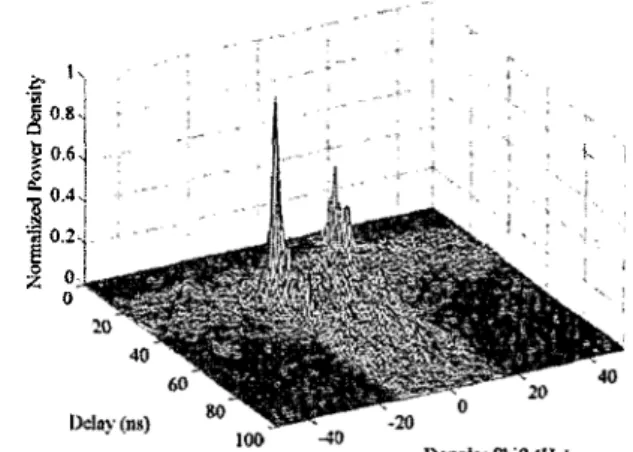
during the experiment, we computed the Scattering Functions corresponding to samples of 128 consecutive Impulse Responses. Fig. 7 represents an average of the Scattering Functions obtained from Impulse Responses recorded between t = 8 s and t = 11 s.
One can observe that the maximum recorded Doppler shift is about 20 Hz in this experiment, which corresponds to a motion speed of 0.5 mis for maximum frequency of 6 GHz. This corresponds to the experimental conditions. This limited Doppler shift demonstrates the ability of the UWB channel sounder to perfonn real time measurements of dynamic channels, as the sampling frequency in the time domain is high enough to avoid aliasing effects. In the current configuration, Doppler shifts up to 4 I 6 Hz could be
recorded.
6. CONCLUSION
ln this paper, we demonstrated the feasibility of developing an UWB channel sounder by applying minor changes to a SIMO wideband channel sounder. Using this technique, most of the channel sounders capable of multiple antennas measurements could be extended to UWB channel sounding. Experimental results were presented, showing the ability of our modified equipment to perform real time UWB measurements with 1 GHz bandwidth and a high dynamic of the Impulse Response. Further modifications, including the increase of the number of partial bands and the use of another Intennediate Frequency, will permit to extend the measurable bandwidth to more than 2 GHz with a rneasurement repetition tîrne as low as 1 .2 ms. Another possible extension of this concept would be to make use of the capabilities of MIMO channel sounders to realize
&' hi �;r
!
i 0.8, 5 1 "0.6-j li. 'l
0.4�. 1
'.! 0.2'1} oJ
0 1-..Fig. 7. Mean Scattering Function experienced between t= 8s and t= Ils.
dynamic UWB measurements on an array of multiple antennas. The UWB channel sounder currently developed at France Telecom R&D will be used in future measurement campaigns, in order to precisely characterize the temporal fluctuations of the UWB Impulse Response in an indoor environment.
7. REFERENCES
[!] P. Pagani, P. Pajusco, S. Voinot, "A Study of the Ultra-Wide Band Indoor Channel: Propagation Experiment and Measuremenl Results", in Proc. /nt. Workshop on Ultra Wideband Systems, Oulu, 2003
[2) V. Hovinen, M. Hümàlainen, T. Pàtsi, "Ultra Wideband lndoor Radio Channel Models: Preliminaty Results", in Proc. IEEE Conf. on Ultra Wide Band Systems and Tech., pp. 7S-79, 2002 [3] J. Kunisch , J. Pamp, "Measurement results and modelling
aspects for the UWB radio channel", in Proc. IEEE Conf. on Ultra Wide Band Systems and Tech., pp. 19-23, 2002
[4] J. Keignart, N. Daniele, "Channel Sounding and Modelling for lndoor UWB Communications", in Proc. !nt. Workshop on Ultra Wideband Systems, Oulu, 2003
[5] A. Alvarez, G. Valera, M. Lobeira, R. Torres, J. L. Gan;ia, "Statistical Impulse Response Mode! for Indoor UWB Channels", in Proc. /ST Mobile and Wireless Comm. Summil,
Aveiro, 2003
[6] M. Win, R. Scholtz, M. Bames, "Ultra-Wide Bandwidtb Signal Propagation for Indoor Wireless Communications", in Proc. IEEE Int. Conf. on Communications, Montreal, 1997
[7] M. Terré, A. Hong, G. Guibé, F. Legrand, ''Major Characteristics ofUWB lndoor Transmission for Simulation", in
Proc. IEEE 57th Vehicular Tech. Conf, vol. 1, pp. 19-23, Spring 2003
[8] R. Kattenbach, O. Weitzel, "Wideband Channel Sounder for Time-Variant lndoor Radio Channcls", in Proc. AP2000
Millennium Conf on Antemws and Propag., Davos, 2000 [9] J.M. Conrat, J.Y. Thiriet, P. Pajusco, "AMERICC, the France
Telecom R&D wideband channel sounder from 2 to 60 GHz", COST 273 Workshop, document TD(03)003, Barcelona, January 2003.