MASTER'S THESIS SUBMITTED TO ÉCOLE DE TECHNOLOGIE SUPÉRIEURE
IN PARTIAL FULFILLMENT OF THE REQUIREMENTS FOR THE
MASTER'S DEGREE IN MECHANICAL ENGINEERING M.Eng.
BY JUNZENG
FINITE ELEMENT MODELING AND SIMULATION OF ROLL BENDING PROCESS FOR FORMING A TRICK CO NI CAL HOLLOW SHAPE
MONTREAL, July 4 2007
THIS THESIS HAS BEENEVALUATED BY THE FOLLOWING BOARD OF EXAMINERS
M. Vladimir Brailovski, President of the Board of Examiners
Département de génie mécanique à l'École de technologie supérieure
M. Zhaoheng Liu, Thesis superviser
Département de génie mécanique à l'École de technologie supérieure
M. Henri Champliaud, Thesis co-superviser
Département de génie mécanique à l'École de technologie supérieure
M. Hakim Bouzid, Membre of the Board ofExaminers
Département de génie mécanique à 1 'École de technologie supérieure
THIS THESIS HAS BEEN PRESENTED AND DEFENDED BEFORE A BOARD OF EXAMINERS AND PUBLIC
July 4 2007
JunZeng
SOMMAIRE
L'objectif du projet exposé dans ce mémoire est de modéliser et de simuler le procédé dynamique du roulage des tôles fortes pour former des troncs de cônes. Le projet est réalisé en utilisant la méthode des éléments finis (MÉF) intégrée dans le logiciel ANSYS/LS-DYNA. Dans cette étude, la configuration pyramidale de roulage continu par flexion avec trois rouleaux est utilisée pour former une pièce conique à partir de tôles planes épaisses. La finalité est de fournir un outil de simulation permettant l'optimisation des paramètres du procédé, et de montrer sa faisabilité pour réaliser des géométries coniques adaptées à la fabrication de couronnes de turbine Francis.
Les relations cinématiques et géométriques du processus sont d'abord développées: elles permettent de minimiser le glissement entre la pièce et les rouleaux en utilisant des rouleaux coniques. Les étapes détaillées de la modélisation par éléments finis incluant le choix des types d'éléments, le maillage, les surfaces de contact avec frottement, les conditions frontières et les liaisons cinématiques sont ensuite présentés. Cette simulation 3D est basée sur la méthode explicite des éléments finis pouvant traiter le comportement de déformation non-linéaire élasto-plastique. Par la suite, la faisabilité de la modélisation du procédé à l'aide de cet outil numérique est exposée à travers un exemple typique. Les résultats du processus dynamique du roulage allant de la tôle plane initiale jusqu'à sa forme conique finale sont visualisés, c'est-à-dire changement progressif de la géométrie ainsi qu'évolution de la distribution des contraintes dans la pièce. Un test de convergence, faisant varier la résolution du maillage, est aussi réalisé pour s'assurer de la pertinence de la taille des éléments choisis. De plus, les forces de réaction et les contraintes résiduelles obtenues par la simulation numérique sont comparées aux résultats d'un calcul analytique simplifié. Pour mesurer la précision géométrique de la forme générée par rapport à celle spécifiée, un algorithme de vérification dimensionnelle a été développé. Cet algorithme, basé sur la méthode d'optimisation non-linéaire de Levenberg-Marquardt, permet de faire un lissage, selon une surface conique, des coordonnées des nœuds de la forme finale obtenue. Par la suite, les déviations sont calculées afin d'analyser les effets des variables du procédé et des paramètres de la simulation sur le résultat final du formage. Ces paramètres incluent le coefficient de frottement, l'épaisseur de la tôle, les propriétés des matériaux, l'agencement spatial des rouleaux et la température de la plaque formée. Cette étude de sensibilité évalue l'influence des paramètres sur les forces de réaction, les contraintes résiduelles et la conformité géométrique de la pièce formée.
FINITE ELEMENT MODELING AND SIMULATION OF ROLL BENDING PROCESS FOR FORMING A THICK CO NI CAL HOLLOW SHAPE
JunZeng
ABSTRACT
The objective ofthe project presented in this thesis is to model and simulate the dynamic roll-bending process for forming a thick plate to a conical hollow shape. The project is realized using the Finite Element Method (FEM), which is integrated into the ANSYS/LS-DYNA software. In this study, the continuous three-roll pyramidal configuration is applied to form a thick plate to a conical hollow shape. The final goal is to provide a simulation tool that allows the optimization of the parameters of the process, and to demonstrate the feasibility of fulfilling the conical geometry adapted to the manufacture of Francis turbine crowns.
The kinematic and geometrie relationships of the process are developed first: they allow sliding to be kept to a minimum between the workpiece and the rolls using conical rolls. Detailed steps for modeling the Finite Elements (FM), including the element type, the meshing, the contact surfaces, the boundary conditions and the constraints, are then presented. This 3D simulation is based on the explicit finite element method, which is able to deal with nonlinear elasto-plastic deformation behavior. Next, a typical example is presented to demonstrate the feasibility of mode ling the process using this numerical tool. The results of the dynamic roll-bending process, going from the initial plate plane to its final conical form are examined, that is, the progressive change in the geometry along with the evolution of the residual stress distribution in the workpiece. A convergence test, which varies the meshing size, is also carried out in order to ensure that the proper element sizes are chosen. Furthermore, the reaction forces and the residual stress obtained through the numerical simulation are compared with the results of a simplified analytic calculation. To compare the geometrie precision of the shape generated with that of that specified, a dimensional verification algorithm was developed. The algorithm, which is based on the Levenberg-Marquardt nonlinear optimization method, allows the smoothing of the coordinates of the nodes of the final shape obtained, based on a conical surface. Next, the deviations are calculated in order to analyze the effects of the variables of the process and of the simulation parameters on the final forming results. These parameters include the friction coefficient, the plate thickness, the materials properties, the spatial arrangement of the outer rolls and the plate temperature. This sensitivity study evaluates the influence of the parameter on the reaction forces, the residual stresses and the geometrie compliance of the final formed piece.
Le marché de la réfection des turbines hydrauliques dans les centrales hydroélectriques est grandissant, car beaucoup d'entre elles arrivent vers la fin de leur vie utile. Afin de minimiser les pertes dues à l'arrêt d'une turbine, les exploitants des centrales fixent des délais auxquels les manufacturiers doivent se soumettre. Dans le cas des turbines de type Francis, le temps de fabrication de la couronne par moulage empêche les fabricants d'être en mesure de répondre aux exigences des exploitants. Ainsi, d'autres procédés de fabrication doivent être étudiés pour atteindre les objectifs en termes de délai de livraison. Le procédé dont il sera question dans ce projet est le roulage pyramidal des tôles épaisses.
Le roulage est un des moyens efficaces pour former un tube cylindrique ou conique à partir d'une plaque plane métallique. Il existe plusieurs techniques de roulage. Le procédé le plus courant est le roulage pyramidal, qui utilise trois rouleaux dont un est en contact avec la surface supérieure de la plaque tandis que les deux autres sont en contact avec la surface inférieure. La plaque est menée par les forces de friction à l'interface de la plaque et des deux rouleaux inférieurs. Le rouleau supérieur est utilisé pour contrôler le rayon de courbure. D'autres procédés tels que le roulage à quatre rouleaux et le roulage à trois rouleaux croque ont été aussi développés dans l'industrie pour améliorer le formage. Cependant, le procédé pyramidal est le plus général et le plus utilisé dans la pratique. Par conséquent, dans ce projet l'étude s'est concentrée sur la modélisation et la simulation dynamique du procédé de roulage pyramidal par la méthode des éléments finis.
Le but de cette recherche sur le roulage est d'optimiser la précision du formage par roulage, d'estimer les dimensions nécessaires des rouleaux pour effectuer ce travail, de déterminer la force d'attraction et les forces de réactions entre les différentes composantes du procédé. D'après une revue de la littérature, il existe peu de travaux de
Vl
recherche antérieurs portant sur l'étude de faisabilité de la fabrication d'une couronne par roulage de troncs de cônes.
Le roulage est un processus complexe dont il reste beaucoup à apprendre et à comprendre. Dans cette optique, la méthode des éléments finis (MEF), avec la capacité de modélisation dynamique constitue, un outil intéressant pour permettre d'étudier en profondeur ce procédé. ANSYS® est un logiciel d'analyse des contraintes d'origine thermique ou mécanique par la méthode des éléments finis. Avec l'intégration de LS-DYNA ®' ANSYS® a la capacité de simuler le processus dynamique, avec de grandes déformations et de grands déplacements, ainsi que les phénomènes complexes d'impacts. Dans le procédé du roulage, où de grands déplacements sont observés, ANSYS® avec LS-DYNA ® intégré permet de simuler et d'étudier ce procédé particulier. Dans ce document, une modélisation paramétrique de la simulation du roulage pyramidal est présentée, en utilisant ANSYS® avec LS-DYNA ®pour étudier la faisabilité du formage d'un cône par cette technique. La simulation numérique permet d'évaluer l'influence des paramètres du procédé sur les forces appliquées, la qualité du formage et la distribution des contraintes résiduelles.
La première étape importante dans la simulation de formage consiste à construire le modèle géométrique. Puisque la procédure du roulage doit satisfaire la relation cinématique, il faut créer un modèle géométrique pour lequel cette relation cinématique est respectée et dont le rayon de courbure est facile à contrôler. Dans le cadre de ce projet, pour faire suite à cette considération, des rouleaux coniques seront utilisés pour former un cône par roulage. Dans la construction du modèle géométrique, les paramètres de configuration tels que la position, la taille des rouleaux et la position de la plaque sont optimisés. De plus, la flexibilité du modèle géométrique créé permet de réaliser des études paramétriques. Les détails du modèle géométrique sont présentés dans le chapitre 1.
Il est à noter que dans la conception du modèle, le critère suivi est sa facilité et sa flexibilité d'utilisation et de réutilisation tout au long de l'étude. Ceci veut dire que ce
modèle doit être capable de simuler la procédure du roulage en choisissant différentes tailles de cônes, différents matériaux, différentes températures et différentes configurations de rouleaux. L'architecture modulaire est donc un point essentiel dans la création de ce modèle comportant plusieurs modules bien définis qui exécutent différentes tâches de modélisation de façon structurée. Ce type de modèle est plus fiable et les composants sont récupérables. Un autre avantage de ce modèle est son extensibilité. Les nouveaux modules sont faciles à modifier pour intégrer d'autres fonctionnalités. Le chapitre 2 présente en détail les différentes étapes des analyses dynamiques effectuées dans cette étude. Les commandes principales du logiciel utilisé ainsi que 1' architecture modulaire du code de simulation sont présentées. Dans la dernière section du chapitre, quelques résultats de simulation, utilisant le modèle établi, sont présentés.
Les résultats de la simulation dans ANSYS® donnent la position atteinte par les nœuds, les forces sur les surfaces de contact et les contraintes résiduelles. ANSYS® permet également de visualiser le processus dynamique de formage jusqu'à la forme désirée à l'aide de l'animation graphique. À la suite d'une simulation, il faut évaluer la différence géométrique entre la pièce formée et le cône désiré. Cependant, la déviation ne peut pas être évaluée directement parce que la pièce formée n'est pas un cône exact. Pour cette raison, un nouvel algorithme de lissage de données non linéaire a été mis en place afin de mesurer quantitativement la déviation géométrique. Dans ce mémoire, cette procédure est appelée la vérification géométrique. Avec cette méthode, la distorsion provenant de la procédure et l'écart entre la pièce réelle et la pièce idéale peuvent être calculés. C'est l'algorithme non linéaire Levenberg-Marquardt qui est utilisé pour lisser un cône dont la somme des carrés des distances est minimum. Ce cône, appelé le cône des moindres carrés, est obtenu par l'algorithme d'optimisation non linéaire mentionné. Le résultat de la position des nœuds générés par ANSYS® est importé dans MATLAB® pour le calcul numérique. Par la suite, 1' écart entre la géométrie de la pièce formée et celle du cône désiré est calculé. Après avoir obtenu le cône des moindres carrés, la vérification géométrique s'effectue et permet de quantifier la conformité et la qualité de
Vlll
la pièce formée par le procédé. Le chapitre 3 présente en détail la procédure de vérification géométrique, la fonction objective et l'algorithme non linéaire. Un cas de calcul est donné à titre d'exemple.
À la suite de l'obtention des résultats de la simulation et de la vérification géométrique, la sensibilité des paramètres est étudiée. Il est assez évident que, pour le processus du roulage, les variations de la dimension du cône désiré, des propriétés de matériaux et de la configuration des rouleaux peuvent influencer les résultats de formage. Dans 1' analyse, chaque rouleau est considéré comme un corps rigide et sa dimension est déterminée par les dimensions spécifiques du cône à former. La configuration des rouleaux est alors représentée par la distance entre les deux rouleaux inférieurs. Dans l'évaluation de l'influence des paramètres du procédé, les principaux résultats sont donc la qualité du formage, la force exercée sur les rouleaux et les contraintes résiduelles.
Dans l'étude de la qualité du formage, les différents matériaux (acier inoxydable ASTM A743 grade CA-6NM, acier ASTM A36, alliage d'Aluminium et de Cuivre AA 6063, Cuivre recuit) sont considérés. Les résultats montrent que la configuration des rouleaux joue un rôle important sur la qualité du formage. Pour un type de matériau donné, il existe une configuration optimale avec laquelle une meilleure qualité de formage peut être atteinte. Une série de simulations, pour différents types de matériaux et dimensions de couronnes, a été réalisée afin de déterminer la meilleure configuration des rouleaux pour une combinaison donnée.
Dans l'étude de la force exercée sur les rouleaux, le facteur épaisseur de la plaque est particulièrement intéressant, car c'est ce paramètre qui donne l'effet le plus significatif. Pour cette partie de l'étude, les dimensions du cône désiré sont: 2 mètres de rayon au sommet, 3 mètres de rayon à la base et 4 mètres de hauteur. Le matériel est de l'acier inoxydable ASTM A743 grade CA-6NM. L'analyse de la sensibilité de l'épaisseur de la plaque fait varier ce paramètre de 1 cm à 10 cm. Les résultats montrent que la force exercée sur les rouleaux augmente en fonction de l'épaisseur sous forme d'une relation quasiment linéaire. De plus, 1' effet de la température de formage de la plaque (20 °C,
200 °C, 400 °C, 600 °C, 800 °C, 1000 °C) est aussi étudié. Les résultats montrent logiquement que la force exercée sur les rouleaux diminue lorsque la température augmente.
Les résultats des contraintes résiduelles générées dans le cône par le procédé de roulage sont en relation avec les forces exercées sur les rouleaux. La variation des contraintes résiduelles est également étudiée pour différentes épaisseurs de plaque et différentes températures. Avec l'augmentation de la température, la plaque devient plus malléable et il est ainsi plus facile de la former. L'intensité des contraintes résiduelles s'en trouve diminuée.
La friction entre les surfaces en contact est aussi étudiée pour vérifier sa sensibilité sur la qualité du formage. En général, un coefficient de friction de l'ordre de 0.3-0.4 est suffisant pour permettre l'entraînement de la plaque par les rouleaux. L'étude de sensibilité montre que la friction entre deux composants (rouleau et plaque) n'affecte pas la qualité de la géométrie formée tant que le coefficient de friction demeure supérieur à 0.3.
Toutes les études paramétriques sont réalisées avec des rouleaux coniques. Cependant, des comparaisons ont été effectuées avec des simulations du roulage utilisant des rouleaux cylindriques. Les résultats montrent que 1 'utilisation de rouleaux coniques permet de contrôler plus facilement le rayon de courbure et de satisfaire la relation cinématique entre la plaque formée et les rouleaux. Les détails de la discussion des résultats sont exposés dans le chapitre 4.
En résumé, les principales étapes de 1' étude du roulage présentées dans ce mémoire peuvent être décrites comme suit : En premier lieu, le modèle géométrique est construit en utilisant des rouleaux coniques. Ensuite, un modèle d'éléments finis est établi et la simulation dynamique de la procédure du roulage est exécutée dans ANSYS® avec LS-DYNA ®. Avec le résultat de la position des nœuds, le cône des moindres carrés est obtenu dans MATLAB® afin de réaliser la vérification géométrique. La sensibilité
x
paramétrique est étudiée en se basant sur les résultats de la simulation et de la vérification géométrique. Selon les différentes analyses de l'étude, les conclusions suivantes sont tirées :
• Pour un cône donné avec un type de matériau spécifique, la qualité du formage dépend de la configuration de rouleaux. Il y a une configuration pour laquelle la qualité optimale du formage peut être obtenue.
• Pour une configuration donnée et un type de matériau spécifique, la force exercée sur les rouleaux augmente en fonction de l'épaisseur de la plaque d'une façon quasiment linéaire. Cependant, pour un cône donné avec un type de matériau spécifique, les forces exercées sur les rouleaux diminuent lorsque la distance entre les deux rouleaux inférieurs est augmentée.
• Même si la configuration influence directement la qualité du formage, il n'existe toujours pas de formulation analytique permettant de calculer la meilleure configuration possible des rouleaux. Il est clair que la simulation numérique telle qu'établie dans cette étude s'est avérée utile et pertinente pour déterminer la valeur optimale de ce paramètre.
Bien que le procédé de roulage des couronnes coniques soit étudié avec succès à 1' aide d'un modèle des éléments finis, plusieurs aspects peuvent être améliorés et peuvent constituer la suite de ce travail de recherche :
• Premièrement, tous les rouleaux dans ce modèle sont coniques. Ce type de rouleau est plus coûteux à fabriquer que des rouleaux cylindriques. Si les rouleaux cylindriques sont utilisés, il est plus difficile de contrôler le rayon de courbure du cône formé et la relation cinématique ne peut pas être satisfaite. Cependant, utiliser les rouleaux cylindriques est plus économique et polyvalent.
Il serait donc intéressant et utile d'établir un modèle de roulage avec des rouleaux cylindriques et d'étudier la faisabilité et la précision atteinte dans ce cas.
• Deuxièmement, tous les rouleaux du modèle actuel sont rigides dans le but de simplifier la construction du modèle. Pour rendre la simulation plus précise, il faudrait étudier le procédé avec des rouleaux déformables.
• Une troisième amélioration du présent travail consisterait à accélérer le calcul numérique. La simulation actuelle prend trop de temps de calcul, spécialement quand la taille des éléments est petite. Une des solutions envisageables pour palier à ce problème est de faire appel au calcul parallèle, ce qui diminuerait le temps de calcul.
• Enfin, un modèle de simulation en boucle fermée pour automatiser le processus de choix des paramètres optimaux serait un atout important. Le modèle actuel permet de déterminer la relation entre la qualité du formage et la configuration des rouleaux. Néanmoins, ce modèle est en boucle ouverte. La mesure de la qualité du formage est indépendante de la configuration des rouleaux. Un modèle en boucle fermée pourrait être plus efficace dans la détermination de la meilleure configuration des rouleaux. Si la qualité du formage est mesurée et transférée à l'entrée du modèle afin d'ajuster à mesure la configuration des rouleaux, la convergence vers une meilleure qualité du formage pourrait être accélérée.
ACKNOWLEDGEMENT
First of all, I would like to extend my appreciation to my director, Professor Zhaoheng Liu and my co-director, Professor Henri Champliaud, who provided me with tons of instructions on how to advance with my work, on how to analyze results, and on how to carry out a geometrie verification of this project. These invaluable instructions guided me in the right direction, and extended my thought process in my Master's project.
Next, I would like to acknowledge the contribution of my wife and daughter. During the course of this project, they offered me all the support I needed in order to dedicate myself fully to my studies. Thanks to them for their understanding and encouragement, particularly during those moments when I encountered difficulties in my project.
Last, but not least, I would also like to thank all my colleagues for their help in this project. I have leamt a lot from them, I will forever cherish the experience I gained from working with them.
Page SOMMAIRE ····••·•·•·•·•··•···•·•·•···•••···•·•·•·•·•·•·•···••·•••·••••··•···•·•·•·•·•·•·•···•·•·•·•·•·•·•• 111 ABSTRACT ... lV RÉSUMÉ EN FRANÇAIS ... v ACKNOWLEDGEMENT ... xii LIST OF FIGURES LIST OF TABLES ABBREVIATIONS NOMENCLATURE INTRODUCTION CHAPTER 1.1 1.1.1 1.1.2 1.1.3 1.2 1.3 1.3.1 1.3.2 1.3.3 1.3.3.1 1.3.3.2 1.3.4 1.3.5 1.3.5.1 1.3.5.2 1.3.6 1.3.7 1.4 ... XVI ...•.••...•.•...•.•.•...•...•.•.•...•.•.•.•.. XIX ..•...••.•.••••.•...•.•••.•...•.•.•.•...•...•...•... XXI ... XXll ... 1
GEOMETRIC SETUP OF THE CONICAL ROLL BENDING PROCESS ... 10
Determination of roll the type ... 11
Curvature control ... 11
Kinematic relationship ... 12
Application of conie al rolls ... 13
Determination ofroll diameter ... 14
Determination of the geometrie pararneters ... 17
H ypothesis and illustration of the final geometrie parameters ... 19
The dimension of the target cone ... 21
The dimension of the rolls ... 21
The dimension of the outer roll ... 22
The dimension of the inner roll ... 22
The outer and inn er apex of the target co ne ... 23
The roll position ... 24
The outer roll position ... 25
The inner roll position ... 26
The dimension and position of the plate ... 27
The initial position of the inn er roll ... 29
CHAPTER2 2.1 2.1.1 2.1.2 2.2 2.2.1 2.2.2 2.2.3 2.2.4 2.2.5 2.2.6 2.2.7 2.2.7.1 2.2.7.2 2.3 2.3.1 2.3.2 2.4 2.4.1 2.4.2 2.5 2.5.1 2.5.2 2.6 CHAPTER3 3.1 3.1.1 3.1.1.1 3.1.1.2 3.1.2 3.1.3 3.2 3.2.1 3.3 3.3.1 3.3.2 XlV
FINITE ELEMENT MODELING AND SIMULATION IN
ANSYS AND LS-DYNA ... 32
Introduction to ANSYS and LS-DYNA simulation program structure ... 3 2 Analysis procedure using ANS YS ... 32
Structure ofthe simulation pro gram ... 33
Finite Element Model ... 36
Element type ... 36
Solid modeling ... 38
Meshing strate gy ... 40
Contact surfaces and friction model ... .41
Constraints and boundary conditions of guiding cylinders and rolls ... 43
Material specification ... 45
Loads specification ... 46
Tilt angle ofthe inner rol1 ... .47
Rotation angular speed ofthe outer roll ... .48
A typical simulation example and its numerical results ... .49
The contour display of the final shape ... 50
The reaction force on the roll ... 51
Discussion of convergence and number of passes in the process .. 52
Convergence studies and comparison of performance ... 53
Number of passes ... 55
Comparison between FEM results and the theoretical calculation for the roll-bending of a cylindrical shape ... 56
Validation ofreaction force ... 57
Validation of residual stress ... 59
Summary ... 61
VERIFICATION OF THE GEOMETRIC ACCORDANCE OF THE FINAL PIECE ... 63
Purpose of geometrie verification ... 63
Assessment of the circularity and the distortion ... 64
Comparison of circularity ... 64
Comparison of distortion ... 65
Assesment of the deviation between the fitted cone and the target cone ... 66
Analysis of sensitivity of the bending quality ... 66
Realization of geometrie verification ... 67
Procedure of geometrie verification ... 68
Geometrie verification criteria ... 68
Similarity to an exact cone ... 68
3.4 3.4.1 3.4.2 3.4.3 3.4.4 3.5 3.5.1 3.5.1.1 3.5.1.2 3.5.2 3.5.3 3.5.4 3.5.5 3.6 CHAPTER4 4.1 4.1.1 4.1.2 4.2 4.2.1 4.2.2 4.2.3 4.2.4 4.3 4.3.1 4.3.2 4.3.3 4.4 4.4.1 4.4.2 4.4.3 4.4.4 4.5 CONCLUSION Levenberg-Marquardt Algorithm [25] ... 70 The problem ... 70 The solution ... 71
Choice of damping parameter ... 72
Algorithm ... 72
Determination of fitted cone ... 73
Distance from a point to a plane ( gi) and to a line (fi) ... 7 4 Distance from a point to a plane ... 75
Distance from a point to aline ... 75
The derivation for
fi
and gj ... 76Distance between the point and the plane ... 77
Objective function ... 78
Normalization ... 78
Typical ex ample of geometrie verification ... 79
SENSITIVITY ANALYSIS OF THE THREE-ROLL BENDING PROCESS ... 82
Study parameters and approach ... 82
Input parameters and output results ... 82
The study approach ... 83
Sensitivity of geometrie parameters ... 84
Influence of plate thickness on bending quality ... 85
Influence of plate thickness on reaction forces on the rolls ... 86
Influence of plate thickness on residual stresses ... 87
Influence ofthe semi-angle of the target cone on bending quality ... 88
Sensitivity of material properties ... 89
Influence of temperature on the bending qua1ity ... 91
Influence of temperature on the reaction forces on the rolls ... 92
Influence of temperature on residual stress ... 92
Configuration parameters ... 93
Influence of span of the outer rolls on bending quality ... 94
Influence of span of outer rolls on the reaction forces on the rolls98 Influence of span of the outer rolls on residual stress ... 99
Sensitivity of friction to the bending process ... 100
Summary ... 101
... 103
Figure 1 Figure 2 Figure 3 Figure 4 Figure 5 Figure 6 Figure 7 Figure 8 Figure 9 Figure 10 Figure 11 Figure 12 Figure 13 Figure 14 Figure 15 Figure 16 Figure 17 Figure 18 LIST OF FIGURES Page
3-D illustration and image of the Francis Turbine [2, 3] ... 1
The three components of the Francis Turbine ... 2
The three-roll continuo us pyramidal bending model ... 5
Illustration ofthree-roll continuous bending machine [16] ... 7
Comparison oftwo configurations of the roll bending machine used to bend conical shapes [ 16] ... 7
The input and output parameters for geometrie setup procedure ... 11
Illustration ofperfect conical shape (a) and distorted conical shape (b) ... 12
Kinematic relationship of tangent speed for driving a pre-bent sector plate in roll-bending process ... 13
Illustration of application of conical rolls in roll bending process: 3D image and 2D section demonstration ... 14
Deflection of roll wh en changing the roll diameter ... 16
Parameters needed for determining the geometrie parameters of the roll-bending process ... 18
Illustration of geometrie parameters of the target cone and roll s ... 20
Illustration of angle between axes ofrolls and the XY, YZ, XZ planes ... 25
Illustration for calculating the dimension and position of he sector plate and the position of the inner roll ... 28
Structure of simulation pro gram ... 35
Illustration of the Fini te Element Model.. ... 36
Illustration ofSHELL163 ... 37
Figure 19 Figure 20 Figure 21 Figure 22 Figure 23 Figure 24 Figure 25 Figure 26 Figure 27 Figure 28 Figure 29 Figure 30 Figure 31 Figure 32 Figure 33 Figure 34 Figure 35 Figure 36 Figure 37 Figure 38 Figure 39 Figure 40
Entities of solid model in ANS YS ... 39
Illustration of meshing plate by specifying width division and arc division ... 41
Friction model ofrolls and plates in the roll-bending process ... 42
Constraints of the bottom and top central node of the outer rolls ... 44
Real behaviour and simplifying behaviour ofbilinear material.. ... 46
Illustration of the tilt angle for pressing down the upper roll in the three-pass process ... 4 7 Tilt angle of the upper roll used for pressing the plate during the process ... 48
The angular speed ofthe outer roll for driving the plate forward and backward in the 3-pass roll-bending process ... 49
The contour display ofthe final shape formed in a typical simulation. 51 Reaction forces on the upper roll ... 52
Convergence study conducted by comparing the reaction force of the inner roll in the Y direction when applying different mesh sizes ... 54
Rapid increase in run-time along with the increase of element ... 55
Two views of the contour display of the final shape obtained by applying the single-pass roll bending process ... 56
Parameters for the theoretical estimation of the reaction forces on the inner roll ... 58
Determination ofresidual stress using graphie interpretation [5] ... 61
Comparison of circularity on different configurations ... 65
Comparison of distortion on different configurations ... 65
Relationship between configuration and bending quality ... 67
Geometrie verification procedure ... 68
Procedure for Levenberg-Marquardt algorithm ... 73
Demonstration offitting cone ... 74
Figure 41 Figure 42 Figure 43 Figure 44 Figure 45 Figure 46 Figure 47 Figure 48 Figure 49 Figure 50 Figure 51 Figure 52 Figure 53 Figure 54 Figure 55 Figure 56 Figure 57 XVlll
Distance from ith point to fitted co ne ... 77
Simulation and geometrie verification sequence ... 80
Graphical comparison of the target cone and fitted cone ... 81
Relation between input parameters and output results ... 83
Variation ofbending quality with different plate thicknesses ... 86
Tendency of reaction forces as plate thickness is increased ... 87
Variation ofresidual stress with changes in plate thickness ... 88
Influence of the semi-angle of the target shape on the bending quality ... 89
Bending quality obtained at different temperatures ... 91
Reaction force ofthree rolls at different temperatures in the Y direction ... 92
Trend of residual stress with increase in temperature ... 93
Deviation of the final shape from the target cone on different spans of the outer rolls when applying the ASTM A743 grade CA-6NM material ... 95
Deviation of the final shape from the target cone on different spans of the outer rolls when applying the ASTM A36 Steel material.. ... 96
Deviation of the final shape from the target co ne on different spans of the outer rolls when applying the AA 6063 Aluminum Alloy material ... 97
Variation of reaction force when applying different spans of the outer rolls ... 98
Residual stress on the application of different span of the outer rolls .. 99
Table I Table II Table III Table IV Table V Table VI Table VII Table VIII Table IX Table X Table XI Table XII Table XIII Table XIV Table XV Table XVI Table XVII Table XVIII
The four-roll continuous bending procedure ... 5 The three-roll pinching-bending procedure ... 6 Equations for calculating the geometrie parameters of the target co ne 21 Equations for calculating the geometrie parameters of the outer roll .... 22 Equations for calculating the geometrie parameters of the inner roll .... 23 Equations for calculating the coordinate of the bottom center of the outer roll ... 25 Equations for calculating the angles between the axis of the outer roll and the planes XY, YZ and XZ ... 26 Equations for calculating the coordinates of the bottom center of the inner roll ... 26 Equations for calculating the angles between the axis of the inn er roll and the XY, YZ and XZ planes ... 27 Equations for calculating the dimension and position ofthe plate ... 28 Equations for calculating the initial position of the bottom center of the inner roll ... 29 Equations for calculating the initial angles between the axis of the inn er roll and the XY, YZ and XZ planes ... 30 Friction between certain components and the plate ... .43 Validation of reaction force on the inn er roll with the theoretical
result ... 59 Comparison of residual stress in simulation with the theoretical result 60 Numerical comparison of the target cone and the fitted cone ... 81 Constant parameters for studying plate thickness sensitivity ... 85 Constant parameters for studying the sensitivity of the temperature ... 90
Table XIX Table XX
Table XXI Table XXII
xx
Material ASTM A743 grade CA-6NM at different temperatures ... 90 Constant parameters for studying the sensitivity of the span of outer rolls ... 94 Material properties of ASTM A36 Stee1.. ... 96 Material properties of AA 6063 Aluminum Alloy ... 97
LSTC Livermore Software Technology Corporation
ANSYS Product of ANSYS corporation; FE analysis and static simulation software
LS-DYNA Product of LSTC corporation; FE analysis and dynamic simulation software
NOMENCLATURE
RP Outer radius of the sector plate
rP Inn er radius of the sector plate
v;,
Outer tangent speed of the sector plate ~ Inn er tangent speed of the sector plateRra Bottom radius of outer roll rro Top radius of outer roll
R Bottom radius of the target cone
r Top radius of the target cone h Height of the target cone
cp Angle of the target cone t Plate thickness
Rr Bottom radius of roll
d Distance between outer rolls
P Apex of outer profile of the target cone S Apex of inn er profile of the target cone
a Angle between the axis of outer roll and the axis of the target cone
a' Angle between the axis of the inner roll and the axis of the target co ne
f3
Angle of outer conical rollfJ'
Angle of inn er conical rolllro Length of outer roll /ri Length of inn er roll
Bxy Angle between the roll's axis projected on XY plane and Y-axis
Byz Angle between the roll's axis projected on YZ plane and Z-axis
p
a
s
Distance between i1h point and the axis of the cone
Distance between i1h point and the bottom plane of the cone
Vector(px,
pY, pJ;
a point on the axis of the cone (not the apex)Vector(ax, aY, aJ; the direction point from p to apex of the cone
Apex semi-angle of the cone
Orthogonal distance from point p to the cone Stress in X direction
Stress in Y direction Stress in Z direction Shear stress on XY plane Shear stress on YZ plane Shear stress on XZ plane Equivalent stress
Elastic strain in X direction Elastic strain in Y direction Elastic strain in Z direction Elastic strain on XY plane Elastic strain on YZ plane Elastic strain on XZ plane Equivalent elastic strain Plastic strain in X direction Plastic strain in Y direction Plastic strain in Z direction Plastic strain on XY plane
XXIV
&pyz Plastic strain on YZ plane &pxz Plastic strain on XZ plane
& Equivalent plastic strain
peqv
/, x Reaction force in X direction + Reaction force in Y direction Jy
+ Reaction force in Z direction
}z
dR Deviation of radius between fitted cane and target cane
dh Deviation ofheight between fitted cane and target cane
R
1 Radius of fitted cane R1 Radius of target cane
H
1 Height of fitted cane
H
1 Height of target cane
Es Sliding energy E1 Total energy
o-Y Yield stress
Background
The hydropower generation equipment market is growmg rapidly. Much of the equipment that is already in service needs to be replaced, and many new hydropower projects require even more such equipment. The problem faced by all hydropower generation system providers is that current manufacturing methods take too long to satisfy customers' requirements.
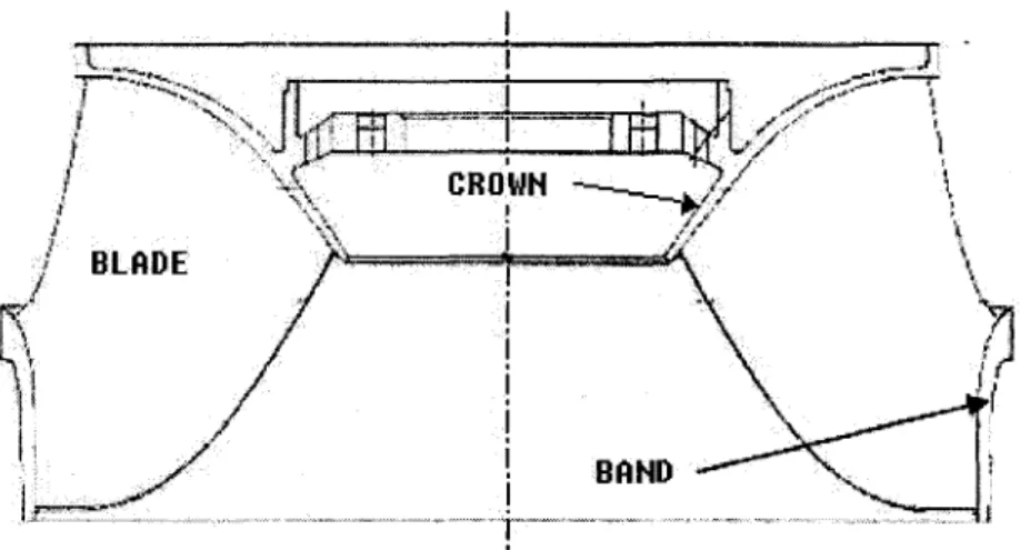
The Francis Turbine shown in Figure 1 is a major piece of equipment in the hydro generation system. lt has a diameter of up to 10 rn (Three Gorges project in China), and a plate thickness of up to 10 cm. The Francis Turbine is comprised of three components: the Crown, Blades and the Band. The Crown has a conical hollow shape, as illustrated in Figure 2 [ 1]. This project is aimed at developing an efficient technique for producing the Francis Turbine Crown.
2
Figure 2 The three components of the Francis Turbine
The manufacturing technique currently used to form the Crown consists of the Foundry and Welding processes. First, a few pieces of the Crown are produced by Foundry, and are then joined together by Welding. The base material used for the Crown is stainless steel (ASTM A743 grade CA-6NM), which has a strong mechanical resistance against corrosion and cavitations. However, this property can be problematic in the Foundry process, particularly because the chrome presented in the material can oxidize, and cause internai faults. Moreover, to ensure that the grains of the steel used are pure, a very slow annealing process is necessary. During the Welding process, preheating is required to reduce residual stresses. This has a major impact on the manufacturing period and for a single crown can be 12-18 months, thus justifying the development of a new manufacturing process.
Severa! manufacturing methods can be applied in forming the Crown of the Francis Turbine. Generally, the manufacturing process involves a combination of certain metal forming techniques, such as Foundry and Welding (which is also current process [1]), or a combination of the Punching or Forging and Welding processes, or a combination of the Roll Bending and W el ding processes.
The continuous roll bending process is an efficient metal forming technique commonly used to produce medium and large cylindrical tubular sections. Severa! bending machines capable of forming the conical tube are currently available in the market. However, no published studies have examined the roll bending process to produce thick conical tubular section of large diameter. This project use FEM, and implements a simulation to study the feasibility of the roll bending process to produce a conical hollow shape.
Introduction to the roll bending process
Bending is the plastic deformation of metals about a linear axis with little or no change in the surface area. Multiple bends can be conducted simultaneously, but to be classified as true bending, and calculated by simple bending theory, each axis must be linear and independent of all others. Roll bending is a continuous form of three-point bending, in which plates, sheets, beams, pipes, and even rolled shapes and extrusions are bent to a desired curvature using forming rolls [4]. In the metal bending industry, the large or medium size of tubular section is usually formed by first bending the metal sheet using stamp bending, and then welding it to form a larger seamed tube. Compared with these techniques, roll bending can be used to form the plate or sheet to a wide range of bend radii. The smallest radius in such cases is just larger than the top roll, while the largest may take up as much room as a workshop. Roll bending is an efficient technique which dramatically reduces the number of seams on the piece as a result of the continuity of the process involved. To obtain a different curvature, the only work required is to choose the right rolls and their right configurations.
A description of the basic princip le and the operation of the roll bending process can be found in [ 4, 5]. C. Bouhelier [ 5] gives the formulas for calculating the spring-back, the reaction forces and the essential power required. Unfortunately, the author does not clearly discuss the process mechanism, and as a result, the final shape is difficult to
4
estimate usmg the formulas. Yang, Ming [ 6] constructed a simulation model for estimating the deformation seen at different periods of the roll bending process. M. Hua [7-12] conducted extensive work studying the four-roll bending process. From his experiments, he discussed the roll bending process mechanism. In 2001, Wei long Hu [13] applied the FEM to study the roll bending process mechanism and came up with a new model, which separated the top or bottom rolls into two parts. In 2004, Zafer Tekiner [14] studied the spring-back of metal sheets with different materials and different thickness in bending dies.
There are three major types of roll bending models available for use, depending on the position of the rolls and their respective functions in the process: the three-roll pyramidal model, the three-roll pinching model, and the four-roll symmetric model. The most common model is the three-roll pyramidal model, as shown in Figure 3, which consists of one top roll and two symmetric bottom rolls. Generally, the diameter of the outer roll is 60-90% that of the inner roll [5]. This model is applied in this project because it is usually employed to bend thick plates [7]. During the bending process, the inner roll presses down to a specified position to control the curvature, and the outer rolls rotate to drive the plate forward. Figure 3 illustrates the whole bending process. This model is easier to set up, but the straight edge part is always present. To resolve this problem, the four-roll model can be applied. Table 1 shows the whole process, using the four-roll model. By setting roll 1 and roll 3 in step 3 and step 5 respectively, the straight edge part can be decreased effectively. The disadvantage of this model is that it requires one more roll, which increases cost and leads to a more complex configuration. The other three-roll model, the pinching model, applies the same idea as in the four-three-roll model to resolve straight edge part problem. Table II presents the process using the three-roll pinching model. When this model is applied, the two outer rolls need to be pinched separately during the edge bending process, in order to eliminate the edge part.
Figure 3 The three-roll continuous pyramidal bending model
Table I
The four-roll continuous bending procedure
1 2 3 4 5 6 7
Feed the No.
2
No.
1 Ro1lsNo.
1 Ro1lswork to
roll move roll move
roll down
, No. 3
ro1l upNo. 2 and
No.
3 ro1lsdown Take
out the
work
center
up upFeed the
Table II
The three-roll pinching-bending procedure
Rough
forrning 1
2 Roughforrning 2
3Edge
bending 1
4Edge
bending 2
5 6R forrning
6Depending on the number of the passes, the roll bending process can be arranged into single-pass and multi-pass categories. The single-pass is more efficient, but requires more bending forces. In sorne situations, such as with the thick plate, the plate usually needs to undergo pre-bending when applying the single-pass, resulting in increased cost. The multi-pass process for its part does not require pre-bending. As illustrated in Table II, the first pass involves rough bending, and the second pass, refined bending. The multi-pass process is therefore the method of choice in the bending of a thick plate or sheet.
In the current roll bending machine market, the three-roll model is the most common configuration encountered. However, the four-roll, and even the two-roll models are also employed in the industry. The roll may be manually-, hydraulically, or electrically-driven, or through a combination of all the preceding configurations. The thickness of the bend plate or of the bend sheet can go up to 25 cm [ 15]. The conical tubular section can be bent using conical rolls or cylindrical rolls with certain standard equipment.
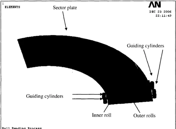
Figure 4 illustrates a roll-bending machine with a three-roll configuration. Figure 5 illustrates the roll-bending machine used to form a conical tube.
Figure 4 Illustration of three-roll continuous bending machine [ 16]
a: conical rolls configuration b: cylindrical roUs configuration
Figure 5 Comparison of two configurations of the roll bending machine used to bend conie al shapes [ 16]
Conical rolls are applied according to Figure 5-a, and their use presents the following advantages:
• Better bending quality • Easy to configure
8
The roll bending process mechanism is a complex dynamic problem. The Finite Element Analysis (FEA) is the approach most commonly used to solve this type of problem. ANSYS is a commercially available software application used to solve the FE problem. With the integration ofLS-DYNA, the complex dynamic problem can even be simulated inANSYS.
The ANSYS program has many finite element analysis capabilities, and offers solutions ranging from a simple, linear, static analysis to a complex, nonlinear, transient dynamic analysis. The analysis guide manuals in the ANSYS documentation set describe specifie procedures for performing analyses for different engineering disciplines. The next few sections of this chapter co ver general steps that are common to most analyses.
A typical ANSYS analysis involves three distinct steps: [17] 1. Build the model.
2. Apply loads and obtain the solution. 3. Review the results.
Geometry can be transferred between ANSYS and ANSYS LS-DYNA in order to perform sequentia1 implicit-explicit/explicit-implicit analyses, such as those required for drop test, spring-back, and other applications. [18]
The procedure for an explicit dynamic analysis is similar to that for any other analysis that is available in the ANSYS program, which is mentioned above.
Limited-duration events (such as severe collisions and blade containment) and large, permanent deformations (within the stamping and forming industries) present engineers with unique simulation challenges. ANSYS LS-DYNA meets these challenges by combining LSTC's LS-DYNA explicit dynamic solver technology with the pre-/post-processing power of the ANS YS software. [ 19]
ANSYS LS-DYNA supports both 2-D and 3-D explicit elements, and features an extensive set of single-surface, surface-to-surface, and node-to-surface contacts as weil as a contact analysis option that automatically creates contact surfaces. ANSYS LS-DYNA also provides optional methods for fast solution processing. The symmetric multiprocessing (SMP) and massively parallel processing (MMP) methods optimize the power of multiple CPUs to deliver explicit simulation results in a fraction of the time. [19]
ANSYS and LS-DYNA support many kinds of materials (refer to [19]). The bilinear isotropie material is selected because the material used in the Francis Turbine manifests bilinear behavior, and bilinear isotropie materials support the parametric definition at different temperatures.
This project aims to setup a FEM model and to simulate the roll bending process using ANSYS with LS-DYNA for forming a thick plate to a conical hollow shape.
CHAPTERl
GEOMETRie SETUP OF THE CONICAL ROLL BENDING PROCESS
The geometrie setup is the procedure used to determine the dimension and the position of all components involved in the roll bending process. For sorne components, the initial position and final position must be determined.
According to the introduction to the roll bending process presented in the last section, conical rolls or cylindrical rolls can be applied to form the conical hollow shape. Before the geometrie setup procedure is defined, a decision must be made with respect the type of rolls to be selected. During the roll bending process, the inner roll is pressed down, and so both its initial and final positions must be determined.
The geometrie setup is especially important for the simulations. The type of rolls, and the position and the dimension of ail components greatly influence the final shape. Before the geometrie setup is chosen, certain parameters must be determined: The dimensions of the desired cone, including the bottom radii, the top radii and the height, and the thickness of the plate must be determined by the client, while the bottom radius of the roll and the span of the outer rolls must be determined by the designer. The geometrie setup must calculate all necessary geometrie parameters aceording to these pre-determined parameters. Figure 6 illustrates the input and output parameters of the geometrie setup. Section 1.2 in this chapter discusses the procedure for determining its value. The other parameter, the span of the outer rolls, as shown in Figure 11, directly influences the final shape. Different values can therefore be chosen for the simulation in order to observe its control to the final shape.
Radius of roUs 1--
r+
Dimension ofrollsSpan of outer rolls
t--
r+
Geometrie r-f-+
Dimension and Calcula ti on position of plateGeometrie
1-- 4 Initial and final
parameters oftarget positions of rolls
Figure 6 The input and output parameters for geometrie setup procedure
1.1 Determination of roll the type
This first step is to determine the roll type. As discussed in the Introduction, two types of rolls - conical and cylindrical - are currently available in the market. However, applying a conical roll can be beneficiai in term of:
• Ease of controlling curvature
• Satisfying the kinematic relationship
1.1.1 Curvature control
For any given cone, the intersection of any plane orthogonal to its axis is a circle. All circles, including those on the top and bottom planes, have the same circularity, but different diameters. When the roll bending process is applied, all circles cannot have the same circularity, unless the contact lines intersect at the apex of the cone. The relationship is shown in Figure 7. In this illustration, L1 and L2 are the lin es representing the contact lines between the cone and the outer rolls, respectively. Only in the situation where L1 and Lz intersect at the apex of the cone can the circularity of the cone be satisfied (as shown in Figure 7 a). However, if L1 and Lz do not intersect at the apex of
12
the cone (as shown in Figure 7 b ), the curvature do es not satisfy the requirement, and the workpiece will be distorted. The discussion above is based on the ideal situation, where there is no sliding between the roll and the plate. Any sliding will distort the final workpiece.
a: perfect conical shape: Ll and L2 intersect at the apex
b: distorted conical shape: Ll and L2 do not intersect at the apex
Figure 7 Illustration ofperfect conical shape (a) and distorted conical shape (b)
1.1.2 Kinematic relationship
The plate that is pre-bent to form a cone is a sector, which is shown in Figure 8. Point 0 is the center of this sector plate; V0 and Vi are the outer tangent speed and inner tangent
speed, respective! y, and rp and Rp represent the inner and outer radii of the sector plate, respectively. During the period of bending process, this sector plate must rotate around the center O. Therefore, V0 and Vi must satisfy the following relationship:
where:
Vo
=
RPFigure 8
Outer and inn er radius of the sector plate Outer and inner tangent speed
Kinernatic relationship of tangent speed for driving a pre-bent sector plate in roll-bending process
1.1.3 Application of conical rolls
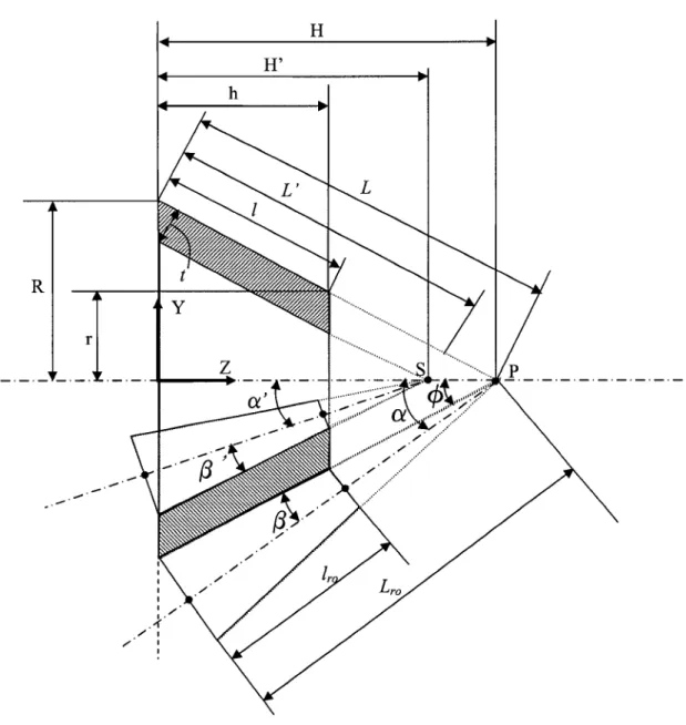
As discussed above, conical rolls can easily satisfy the two requirernents for bending a conical hollow shape. As illustrated in Figure 9, this project ernploys conical rolls for the simulations. According to this figure, the axes of ali rolls intersect at the apex of the desired cone. Point P is the outer apex of the cone and point S is the inner apex. Based on this relationship, the following equation is obtained.
RD ~ Rp R
= = =
-(1.2) where:
Bottorn and top radius of outer roll
AU:>.,.~ !;'pf F,U Figure 9 1\N R ...
Illustration of application of conical rolls in roll bending process: 3D image and 20 section demonstration
For the same reason, the dimension of the inner roll is determined as follows:
R R'
_,
__
14
r' ( 1.3)
where:
Ri, ~: Bottom and top radii of the inner roll
R', r': Inner bottom and top radii of the target cone
1.2 Determination of roll diameter
Before we can set up a geometrie model, the dimension and the position of ali roUs must be determined. As already pointed out, the proportion of the top-bottom radius of the roll must be the same as that of the target cone. If one roll radius is known, then the dimension of all the roUs can be determined.
In this simulation, ali rolls are considered as rigid bodies. However, in real applications, the rolls exhibit deflections. Therefore the radius of the roll must be carefully determined to limit deflection to a reasonable range. The following section discusses the procedure for determining the radius of a roll.
Hypothesis:
To simplify the calculation, the conditions below are present: • Cylindrical roll
• Material is steel with elastic modulus (E) of 200GPa • Uniform pressure
• Simply supported ends
Therefore, the maximum deflection is calculated as follows: [20, 21]
5wL4 5wL4
v -
---:-max - 384EI - 12E7rd4 (1.4)
where:
w :
Distributed load on the bearnL : Length of the bearn
E : Elastic modulus
1 : Moment of inertia
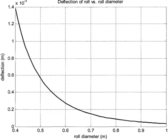
From the result of section 2.5.1, the reaction force on the lower roll is almost 1978 kN. Suppose the roll is cylindrical and the load in distributed uniformly, and that the length and elastic modulus are known. The deflection of the roll is therefore a function of the radius ofthe roll. This relation is illustrated in Figure 10:
x 10-3 Deflection of roll vs. roll diameter 1.4~~~~~~~~~~~~-,~~~~~~~~~~~~ 1 1 1 1 1 ---,---,---.,---r---r---1 1 1 1 1 1.2 1 1 1 1 1 1 1 1 1 1 1 1 1 1 1 1 1 1 1 1 1 ' 1 1 1 1 1 1 ' ' 1 1 1 1 1 1 1 1 1 1 1 ,...,
g
0.8 c: 0u
Q)15
0.6 "0 ' 1 1 1 1 0.4 ···:······1···'···i···r···
0.2 ---:---1--- ---j---;---r---. ' OL_~~~~~~~~~~~-L~~~~~~~_J~~~~ 0.4 0.5 0.6 0.7 0.8 0.9 roll diameter (m)Figure 10 Deflection of roll wh en changing the roll diameter
16
As illustrated in Figure 10, the maximum deflection is 0.6 mm when diameter of the roll is 0.5 m. This value is nearly 0.1% of the radius of the target cone and therefore is acceptable. Actually, equation 1.4 is based on the hypothesis of cylindrical roll. In this simulation, 0.25 rn is the radius of the smaller side. Therefore, the deflection must be less than 0.3 mm when applying conical rolls.
Note: The discussion above is based on the outer roll. For the pyramid model (refer to Figure 3), the radius of the inn er roll is 1.2-1.5 times of the radius of the outer roll [ 5].
1.3 Determination of the geometrie parameters
The determination of the geometrie parameters involves tho se of the initial status and of the final status. Initial status denotes the status prior to bending while final status denotes the status when roll-bending process is completed. In fact, the set-up of rolls can be determined according to the dimensions of the plate, the dimensions of the target cone and the span of the outer rolls. All these pre-determined parameters are known, except for the span of the outer rolls which is varied and will be determined by the designer.
The following list presents the known parameters for determining the final geometrie parameters (see Figure 11).
Parameters specified by client
R: Bottom radius
r: Top radius
h: Height
t: Plate thickness
Parameters determined by engineer
Rr: Bottom radius of roll; determined by material strength
d: Span of outer rolls; no equation to determine it: try many values; the optimal value is determined by the simulation
18
Rr
Figure 11 Parameters needed for determining the geometrie parameters of the roll-bending process
Parameters to be determined (see Figure 12 and Figure 13):
P: Apex of outer profile of the bended cone S: Apex of inner profile of the bended cone
a: Angle between the axis of the outer roll and the axis of the desired cone a': Angle between the axis of the inner roll and the axis of the desired cone
fl:
Angle of outer conical rolls /]': Angle of inner conical rollL: Length of outer li ne of the target cone L': Length of inner li ne of the target cone
L,." : Distance from bottom to the apex
l,0: Length of outer rolls
L,.i : Distance from bottom to the apex lri: Length of inner rolls
qJ: Angle of the desired cone
Bxy: Angle between roll axis projected on XY plane and Y-axis Byz: Angle between roll axis projected on YZ plane and Z-axis B,ë: Angle between roll axis projected on XZ plane and Z-axis
1.3.1 Hypothesis and illustration of the final geometrie parameters
Figure 12 illustrates the final position of the rolls and the target cone. The positions of the rolls are determined based on the following hypothesis:
• The length of the roll is equal to the width of the plate.
• Ali rolls have a conical shape the radius of which conforms to the relationships of equation 2.2 and equation 2.3.
20 H
H'
h R rFigure 12 Illustration of geometrie parameters of the target cone and rolls
1.3.2 The dimension of the target cone
Table III lists the equations used to calculate the geometrie parameters of the target cone. The given geometrie parameters of the target cone are the bottom and top radii, the height of the target cone, and the plate thickness. With these parameters, the semi-angle of the target cone rp , the distance from inn er apex S to bottom L ' and distance from outer apex P to bottom L can be calculated (see Figure 12).
Table III
Equations for calculating the geometrie parameters of the target co ne
Angle of the target cone
( R-r)
rp =tan-' -h-Distance from outer apex P to bottom
L= R
sin( cp)
Distance from inner apex S to bottom
R- t
L'= cos( cp)
sin( cp)
1.3.3 The dimension of the rolls
As described above, the roll is assumed to be a rigid body with a conical shape. Therefore, the radius of all rolls is determined by the bottom radius of outer roll R, .
Section 1.2 discusses the method used to determineR, . The radius of the inner roll is (1.2-1.5) R,. The dimension of all rolls can be obtained based on R, and the dimension ofthe target cone.
22
1.3.3.1 The dimension of the outer roll
Table IV lists the equations used to ealeulate the geometrie parameters of the outer roll, including the bottom radius R,0 , the semi-angle of the roll
f3,
the angle between the rollaxis and the target eone axis
a,
and the length ofthe roll 1,0 (see Figure 12). With these parameters, a roll ean be ereated direetly in ANSYS.Table IV
Equations for ealeulating the geometrie parameters of the outer roll
Bottom radius R =R ro r
Angle of the roll
f3
.
-l(R,)=sin
-L
Angle between the axis of the eone and the axis of a=rp+/3 the roll
Fulllength of the roll Lro = L · eos(/3)
Length of the roll 1,0 = 1 · eos(/3)
1.3.3.2 The dimension of the inn er roll
Table V lists the equations used to ealculate the geometrie parameters of the inner roll, including the bottom radius R,;, the semi-angle of the roll
f3
1, the angle between the axis
of the roll and the axis of the target eone a 1
, the fulllength of the roll Lri and the length
Table V
Equations for calculating the geometrie parameters of the inner roll
Bottom radius R,;
=
(1.2 0 1.5)R,Angle of the roll
f3
. ,
R ·' =
sm- ( ____!!_) L' Angle between the axis of cone and the axis of the a'=cp-jJ'roll
Fulllength of the roll L,;
=
L 'cos(/3 ')Length of the roll l,;
=
l'· cos(/3 ')1.3.4 The outer and inn er apex of the target cone
The equations below present the method for calculating the apex of the target co ne. P is the outer apex and Sis the inner apex (see Figure 12). His the height from the bottom of the target cone to its apex.
R P=[O,O, ] tan( cp) (1.5) e
s
=
[0, 0,z
p - • ] sm( cp) (1.6) where:R : Bottom radius of the target co ne
cp: Semi-angle of the target cone
Z P : Z-coordinate of point P
e : Thickness of the plate
24
1.3.5 The roll position
The last sections have provided the equations for calculating the dimensions of the rolls. This section for its part discusses the method for obtaining the positions of all rolls. Because the axes of the two outer rolls intersect at the apex of the target co ne, the factors used to determine their positions are the angle between the axis and the XY, XZ and YZ planes, as shown in Figure 13. Likewise, the position of the inner roll is determined by the angle between its axis and the three planes. Figure 13 (a), (b) and (c) represent the front view, the left view and the top view, respectively. In Figure 13, point Q is the bottom center of the outer roll, and Q' is the bottom center of the inner roll.
The outer broken-line circle is the enveloped circle ofthe bottom center of the outer roll, and the inner broken-line circle is the enveloped circle of the bottom center of the inner roll. Ra is the radius of the outer enveloped circle and Ri is the radius of the inner
enveloped circle. 1 1 1 1 1 \
y
-.-. .-
·- ·--·-·-(b)
Figure 13 1.3.5.1 X H
. -
. - . - . _J, _,/, . .,...-·\-e~:
z
(c)
Illustration of angle between axes of rolls and the XY, YZ, XZ planes (a) View ofYZ plane; (b) View ofXY plane; (c) View ofXZ plane
The outer roll position
Table VI lists the equations used to calculate the coordinates of the bottom center of the outer roll. Table VII lists the equations used to calculate the angles between the axis of the outer roll and the XY, YZ, XZ planes.
Table VI
Equations for calculating the coordinate of the bottom center of the outer roll
~ RQ
=
Lra sin( a) XQx
=d Q 2 YQ YQ=~R/
-XQ2 ZQ ZQ =Rra sin( a)Table VII
Equations for calculating the angles between the axis of the outer roll and the planes XY, YZandXZ
Angle between the axis and the XY plane
x
e
= sin-1 (___g_) zyR
0
Angle between the axis and the YZ plane
x
e
= tan-1( Q )
yz H-Z
Q
Angle between the axis and the XZ plane y
e
= sin-1( Q )
xz H-Z
Q
1.3.5.2 The inner roll position
26
Table VIII lists the equations for calculating the coordinates of the bottom center of the inner roll. Table IX lists the equations for calculating the angle between the axis of the inner roll and the XY, YZ, XZ planes.
Note: The position of the inner roll determined in this section is the final position of the inner roll. Furthermore, the initial position of the inner roll must be determined as well. This will be discussed in 1.3.7.
Table VIII
Equations for calculating the coordinates of the bottom center of the inner roll
Ri R,. = L,,. sin( a ')
XQ' XQ. =0
YQ· YQ. =R,.