Paper ID: 14 Page 1
Comparison of a scroll, a screw, a roots, a piston expander and a
Tesla turbine for small-scale organic Rankine cycle
O. Dumont1*, L. Talluri2, D. Fiaschi2, G. Manfrida2 and V. Lemort1
1Thermodynamics laboratory, University of Liège, 4000 Liège, Belgium
olivier.dumont@ulg.ac.be
2Department of Industrial Engineering, Università degli Studi di Firenze, Viale Morgagni 40-44, 50134 Firenze (FI) Italia
*Corresponding Author
ABSTRACT
The aim of this paper is to assist the selection of the expander for small-scale organic Rankine cycles, based on an experimental comparison of piston, screw, scroll, roots expanders and Tesla turbine, the latter investigated by a specifically developed simulation model. First, based on a literature review, a comparison of these five expansion machines technologies is performed. Afterward, four expanders [2-4 kW] were tested in a small-scale ORC unit with R2[2-45fa as working fluid. The calibration of models based on the measurements allows the prediction of the isentropic efficiency under optimized conditions, in spite of the operating range of the test-rig. A 2D validated model simulates the performance of the machine Tesla Turbine. A comparison of costs and compactness of the 5 investigated expander technologies is also performed. Finally, based on the working charts achieved with the simulation models and on experimental and practical aspects, some guidelines are drawn to help the reader in the selection of the most suitable expander technology for a given application.
1. INTRODUCTION
Many theoretical investigations have demonstrated the considerable influence of the expander efficiency on the overall performance of ORC powerplants (Qiu et al., (2011) and Ziviani et al., (2013)). A single expander technology cannot be identified as optimal for every application, particularly for micro and small-scale systems (Bao and Zao, 2013; Qiu et al., 2011; Vanslambrouck et al., 2011; Weiss, 2015; Zywica et al., 2016). The best technology depends on a large number of parameters, including the cycle operating conditions, the system compactness, cost constrains and components availability. It is, therefore, necessary to evaluate and to compare the performance of different expander technologies, in order to assist the selection of the best candidate for a given application.
In this work five machines, namely a roots supercharger (Figure 1a), a modified hermetic scroll compressor (Figure 1b), a twin-screw expander (Figure 1c), a swash-plate piston expander (Oudkerk et al., 2015) (Figure 1d) and a Tesla turbine (Figure 1e), for a micro-scale ORC working with R245fa fluid are compared . This refrigerant is selected because it is one the most widespread fluids for small-scale ORC power system (<10kWe), when the heat source temperatures range between 100°C and 200°C (Dickes et al., 2014; Quoilin, 2011).
Table 1 summarizes the differences between these five expander technologies when used in ORCs. Piston expanders are suited for low volume flow rates (< 75 l/s) and low power applications (~10 kW). They present the possibility of working with high inlet temperatures, inlet pressures and pressure ratios. Those machines can manage very high pressure ratios (up to 14), which may be advantageous in some
Paper ID: 14 Page 2
applications. Their efficiency is, so far, always below 70%. It is known that piston expanders can handle a small fraction of liquid, but no extensive literature can be found on this topic.
Tesla turbine
e)
Figure 1: Different expander technologies (Lemort and Legros, 2016; Mandal and Saha, 2017)
Scroll expanders benefit from few rotating parts. They present a limited expansion pressure ratio, since the maximum volume ratio is usually limited to 4.2. A mean of increasing the volume ratio also consists in associating two expanders in series (Mandal and Saha, 2017). These expanders can handle very high mass fractions of liquid (>80% - Lemort et al., 2009)). Their maximum power output is at the same level of the piston expanders. Also, the maximum temperature and pressure of 250°C and 40 bar are reported (Seher et al., 2012). Screw expanders present several advantages, such as high possible shaft speeds (up to 20,000 RPM), compactness (see Section 3.2), and capability of handling wet expansions (>90%). It appears that screw expanders can work in relatively low power area, but are, actually, mainly adopted in a power range higher than the scroll or piston expander, due to manufacturing costs. Roots expanders are not frequently encountered. Technical and scientific literature about these machines is scarce. Their volume ratio is generally close to one, which drives towards low pressure- ratios applications. The power output of roots expanders ranges approximately from 1 to 30 kW, with highest rotational speed of about 20,000 rpm. These machines can handle a large fraction of liquid in expansion (Dumont et al., 2018). The Tesla expander is a bladeless turbine, made of one or more nozzles, that inject the working fluid tangentially inside the rotor, which consists of multiple stacked parallel disks, assembled very close to each other and forming very tight gaps (of the same order of magnitude of the boundary layer thickness), where the fluid transfers work to the machine through viscous effects. The fluid enters tangentially at the periphery of the rotor and follows a spiral path before exiting through the rotor inner radius. The suitable power for this expander is generally considered between few Watts and some tens of kWs. It is claimed that Tesla turbine can handle wet expansion (Rice, 1965; Steidel and Weiss, 1976) and that it does not present severe constraints in terms of temperature, pressure and shaft speed like the volumetric expanders, thanks to its simple structure.
Table 1: State of the art of scroll, piston, screw, roots, Tesla (Dumont et al., 2018; Lemort and Legros, 2016;
Rice, 1965; Steidel and Weiss, 1976; Ziviani et al., 2013)
Parameter Scroll Piston Screw Roots Tesla
Displacement [l/s] 0.76-32 [1.25-75] [25-1100] - N/A Power [W] [0.005-10,000] [0.001-10,000] [2,000-2e5] [1000-30,000] [0.005 – 30,000] Max. rotational speed [RPM] 10,000 8,000 21,000 20,000 -
Built-in volume ratio [1.5-4.2] [2-14] [n.a.-8] ~1 N/A
Maximum pressure [bar] ~40 70 - - -
Max. temperature [°C] 250 560 - - -
Two-phase flow handling Yes Low Yes Yes Yes
Isentropic efficiency [%] 87 70 84 47 60
In 2018, a comparison of four volumetric expanders was proposed based on experimental investigations (Dumont et al., 2018). Furthermore, the performance was simulated under optimal conditions, thanks to validated semi-empirical models. According to the results, and corroborated with a literature review, general guidelines were derived to help engineers in selecting an optimal technology for a given
Paper ID: 14 Page 3
application. Anyhow, Dumont et al. (2018) only focused on the isentropic efficiency criterion. The present manuscript is aimed at improving the comparison including additional comparison criteria like cost and compactness and an additional technology, namely the Tesla turbine.
2. METHODOLOGY
This study investigates 5 different technologies of expanders, considering different aspects. This includes compactness, isentropic efficiency, Ns-Ds diagram and costs.
First, the isentropic efficiency, as defined by Eq. 1, is optimised for different working conditions by adjusting the shaft speed of the expander. On this basis, it is possible to draw maps of performance, depending on the inputs of a given application (condensation temperature and expander supply temperature).
𝜂𝑖𝑠 =
𝑊̇𝑒𝑙
𝑚̇(ℎ𝑒𝑥𝑝,𝑠𝑢− ℎ𝑒𝑥𝑝,𝑒𝑥,𝑖𝑠)
(1) Secondly, a compactness factor is defined as the ratio of the nominal shaft power divided to the total volume of the expander and mechanical parts (not considering the shaft, the generator and the casing). This criterion is useful for some applications where the small size and compactness are mandatory (e.g. transportation sector), but also to reduce the material costs.
Moreover, a comparative cost analysis is proposed. In a former work (Guillaume, 2018), the costs of the expander technologies are estimated using Solidworks software. 3D sketches have been performed, or directly used when available, to establish the list of the main parts of the machines and to evaluate their costs as a function of a typical geometrical parameter. The process assumes the type of material, the manufacturing process and a serial production of 20,000 units per year. Stainless steel material was selected for parts directly in contact with the working fluid while carbon steel was chosen for the remaining, so as to reduce the costs. For the same reason, the moulding process has generally been preferred to machining (Guillaume, 2018). The costs are correlated to the exhaust swept volume of the expander (V). For the Tesla turbine, the same approach was applied, taking the developed prototype geometry as a reference (Manfrida et al., 2018; Talluri et al., 2018). The prototyping costs of the Tesla turbine were correlated to the external rotor diameter of the expander. It is expected that the proposed correlation, based on material and manufacturing costs for one prototype, largely overestimates the real production prices (at least one order of magnitude), as various components of the turbine can surely be geometrically optimized when designing a machine for series production. The cost correlations are listed in Table 2.
Table 2: Cost of the expander
Expander Cost (€) Scroll 21.556 ∙ V0.6271 Screw 20.445 ∙ V0.7342 Piston 6.0999 ∙ V0.8095 Roots 10.445 ∙ V0.7342 Tesla 3373.3 ∙ d10.652
Finally, a Ns-Ds diagram, typically used for turbomachinery design, is considered (Capata and Sciubba, 2012). This approach allows for the definition of each machine suitable operation range. The specific speed (Ns) corresponds to the expander speed required to handle a 1 m3/s volumetric flow rate with an available 1 meter total head. For volumetric expanders, Ns is not directly related to the total head. The specific diameter (Ds) is the diameter required to handle a 1 m3/s volumetric flow rate with an available 1 meter total head. Therefore, this parameter gives an indication about the size of the machine.
The proper choice of an expander technology is not yet straightforward and such an experimental comparison between different expander technologies does not exist in the literature. As mentioned in the introduction, the four volumetric expanders are simulated thanks to a validated semi-empirical model. The same power range [2-4] kW and the same working fluid (R245fa) were considered for the different machines. All the details concerning the experimental data, the parameters of the models and the assumptions are described in (Dumont et al., 2018). No experimental data was yet available for the
Paper ID: 14 Page 4
Tesla turbine with the same working fluid. For this the reason, a 2D validated numerical model is used. It includes the losses of each element and introduces an innovative rotor model. The main optimizing parameters of the turbine, such as the rotor inlet/outlet diameter ratio, channel width-rotor diameter ratio and tangential velocity-rotational speed ratio at rotor inlet are optimized for each configuration (Ciappi et al., 2019; Manfrida and Talluri, 2019; Talluri et al., 2018).
3. RESULTS
3.1 Efficiency
For each expander at each pressure ratio within the 1 – 15 range, the isentropic efficiency is optimized vs. the shaft speed (Figure 2). The reference working fluid is R245fa in all cases, the condensation temperature is set to 30 °C and the superheating is fixed at 5 K.
Figure 2: Isentropic efficiency versus pressure ratio for the five expanders.
From Figure 2, it appears that an optimising pressure ratio exists for each machine. For the volumetric expanders, under-expansion and over-expansion losses may appear at pressure ratios different from the optimal (design) value. For the Tesla turbine, the optimising pressure ratios are around 3. This figure also shows that the Tesla turbine and the roots expander work properly at low pressure ratios. On the contrary, the piston expander works effectively at pressure ratios higher than 4.5. Shaft speeds at maximum efficiency are respectively 10 000, 3000, 5000, 3000 and 2500 RPM for the screw, the roots, the scroll, the piston and the Tesla turbine.
Figure 2 only presents the results at fixed condensation pressure. However, some applications (e.g. combined heat and power) require different levels of cold source temperature. Therefore, a mapping of the optimal performance was done for each expander as a function of the condenser pressure and expander inlet temperature. The results are shown in a four quadrant graph (see Figure 3) for which the different axes are all positive and symmetric to the origin (each quadrant is referring to an expander). Four curves are displayed to inform the variations of the optimal isentropic efficiency as a function of operating conditions. For a given supply temperature, two condensing pressures lead to an identical efficiency, because of under- and over- expansion losses. The top horizontal line (i.e. the highest inlet temperature) in each quadrant refers to the upper bound temperature of each expander (see Table 4). The black dotted horizontal line represents the critical temperature of the refrigerant. Classically, the expander inlet pressure and temperature are related by a constant superheat. Only for the piston machine and the Tesla turbine, the maximum pressure is reached before the upper possible temperature. For the piston engine, the supply pressure is imposed at its highest possible value and the supply temperature is increased to cover wider ranges of power, while for the Tesla turbine the maximum considered temperature is 150°C, which is just slightly lower than the critical value.
Paper ID: 14 Page 5
Figure 3: Mapping of isentropic efficiency based on condensation and expander supply temperature. The roots
mapping can be found in (Dumont et al., 2018)
The scroll and screw expander maps are rather close. Whatever the considered isentropic efficiency, the screw expander operating range is slightly narrower, because of its inlet temperature limitation and, more generally, its lower isentropic efficiency. As expected, in this case, the piston technology has less possibility of working at low inlet temperature, but shows the widest running range because of the high allowed temperature and its high volume ratio. The roots expander and the Tesla turbine have rather low efficiency, except at low pressure ratios (supply temperature close to the condensation temperature) where it does not suffer from over-expansion contrary to the other technologies.
3.2 Compactness
As already mentioned, compactness is of primary importance for some applications such as, for example, transportation. Figure 4 represents the compactness, as defined in the methodology section, for each expander. The most compact machine is the screw, followed by the scroll, the roots and/or Tesla and, finally, the piston. However, for very low pressure ratios, the roots expander is more compact than the scroll, due to its intrinsic lower over-expansion losses. The piston expander is a prototype from 2015 which explains the relatively low compactness.
Figure 4: Compactness of the five expanders 3.3 Ns-Ds diagram
Paper ID: 14 Page 6
Figure 5 proposes a comparison of the Ns-Ds diagrams for all the expanders. Globally, all display a similar operating range. The Tesla turbine behaviour is the opposite of classical turbo expanders, which usually cover higher specific speeds (Baljé, 1962). Once again, the scroll and screw expanders display very similar trends. A zoom is proposed for the Tesla turbine (Fig. 5 b)), because the specific speed is not linearly correlated to the specific diameter for this machine, unlike volumetric expanders.
a) b) (z-axis = isentropic efficiency)
Figure 5: Ns- Ds diagram. a) all expanders, b) Tesla 3.4 Costs
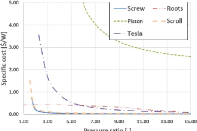
The specific costs, evaluated through the approach described in the methodology section, are plotted in Figure 6 for each expander as a function of the pressure ratio. It is shown that the scroll and screw expander present very similar costs whatever the pressure ratio. The piston expander technology is always the most expensive in this study. The roots expander is cheaper than the scroll and screw expanders for a given size, but only for pressure ratios below 1.5. The Tesla turbine specific cost is higher than those of scroll and screw expanders at low pressure ratios, but it is really close at higher pressure ratios. Indeed, it is expected that for an optimized design of a Tesla turbine, the production of more units should remarkably reduce the specific costs, presumably into an even lower range than that of scroll and screw expanders.
Figure 6: Specific costs of the expander in function of the pressure ratio 3.5 Summary
The summary of the conclusions regarding volumetric expanders is well known (Dumont et al., 2018). “Based on the scientific literature, one of the main criteria to take into account when selecting a volumetric machine is the size range of the system. In the field of tens kW, screw expanders are usually recommended. In the range lower than ~ 2.5 W, scroll and piston machines could be chosen.” However, this paper shows that a screw expander can achieve acceptable efficiency levels even in the size range below 10 kW. Besides the size range, other technical constraints must be taken into consideration, such
Paper ID: 14 Page 7
as the highest allowable operating pressure and temperature, the ability of working without lubrication, the highest achievable built-in volume ratio, the machine cost and compactness. For instance, the piston expander may be used for applications with the highest supply pressure and temperature. Therefore, it allows achieving higher shaft power output, if those conditions cannot be achieved by the other technologies. However, piston expanders only handle limited wet expansions. In terms of compactness, the best choice are screw expanders followed by the scroll, Tesla turbine, piston and roots (see Table 4). The flexibility (i.e. the ability of working efficiently under off design conditions), is important for the screw expander through its wide range of shaft speed.
In terms of cost and compactness, the screw and, secondly, the scroll expander, seems to be the most promising. It is interesting to compare the characteristics of volumetric expanders with the Tesla turbine. They are closer to those of volumetric expanders, such as rotational speed, power, pressure and temperature operational ranges; with the exceptions of quasi-independency on pressure ratio with rotational speed and high shaft speeds.
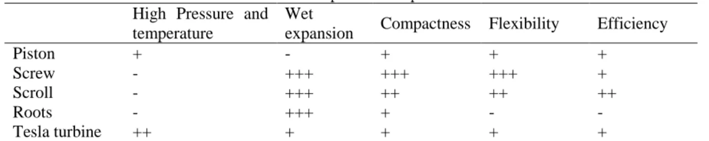
Table 4: Comparison of expanders
High Pressure and temperature
Wet
expansion Compactness Flexibility Efficiency
Piston + - + + + Screw - +++ +++ +++ + Scroll - +++ ++ ++ ++ Roots - +++ + - - Tesla turbine ++ + + + +
4. CONCLUSIONS
Five different expanders technologies (namely scroll, screw, roots, piston and Tesla turbine) were compared based on both theoretical models and experimental data, when available. A discussion to help the selection of the most appropriate expander for a small-scale ORC is also proposed. Based on the state of the art and on the proposed analysis, the selection of the most appropriate expander technology should be conducted in parallel with the selection of the ORC architecture, size range, operating conditions and working fluid for the selected application.
Generally, an optimizing pressure ratio was found for each investigated technology, with the lowest values (very close to 1) for Tesla and roots expanders. The latter ones also showed the lowest levels of efficiency, except at low pressure ratios. In this field, the roots technology offers the highest compactness. Finally, for Tesla turbine the specific speed and diameter are not linearly correlated.
NOMENCLATURE
Ds specific diameter (-)
ṁ Mass flow rate (kg/s)
Ns Specific speed (-) V Volume (m3) Ẇ Power (W) η Efficiency (-) Subscript el Electrical ex Exhaust exp Expander is Isentropic su Supply
REFERENCES
Paper ID: 14 Page 8
Bao J., Zhao L., 2013. A review of working fluid and expander selections for organic Rankine cycle. Renewable and Sustainable Energy Reviews; 24: 325-342.
Capata R., Sciubba E., 2012. Use of modified Balje maps in the design of low Reynolds number turbocompressors, Proceedings of the ASME 2012 International Mechanical Engineergin Congress & Exposition IMECE 2012, Houston, Texas, USA.
Ciappi L., Fiaschi D., Niknam P.H., Talluri L., 2019. Computational investigation of the flow inside a Tesla turbine rotor, Energy, 173: 207-217.
Dickes R., Dumont O., Declaye S., Quoilin S., Bell I., Lemort V., 2014. Experimental investigation of an ORC system for a micro-solar power plant, Proceedings of the 22nd International Compressor Engineering Conference at Purdue.
Dumont O., Parthoens A., Dickes R., Lemort V., 2018. Experimental investigation and optimal performance assessment of four volumetric expanders (scroll, screw, piston and roots) tested in a small-scale organic Rankine cycle system, Energy, 165, 1119-1127.
Guillaume L., 2018. On the design of waste heat recovery organic Rankine cycle systems for engines of long-haul trucks, PhD thesis, Liège (Belgium).
Lemort V., Legros A., 2016. Positive displacement expanders for Organic Rankine Cycle systems, in: Macchi M. and Astolfi M., Organic Rankine Cycle (ORC) Power Systems, Technologies and Applications, 1st Edition, Woodhead Publishing, Elsevier.
Lemort, Vincent & Bell, Ian & Groll, Eckhard & Braun, Jim., 2019. Analysis of Liquid-Flooded Expansion Using a Scroll Expander.
Mandal, A., and Saha, S., 2017. Performance analysis of a centimetre scale Tesla turbine for micro-air vehicles, 2017 International conference of Electronics, Communication and Aerospace
Technology (ICECA), Coimbatore, 62-67.
Manfrida G., Pacini L., Talluri L., 2018. An upgrade Tesla turbine concept for ORC applications, Energy, 158, 33–40.
Manfrida G., Talluri L., 2018. Fluid dynamics assessment of the Tesla turbine rotor, Thermal Science. Oudkerk J.F., Dickes R., Dumont O., Lemort V., 2015. Experimental performance of a piston
expander in small-scale organic Rankine cycle, Proceedings of the International Conference on Compressors and their Systems.
Qiu G., Liu H., Riffat S., 2011. Expanders for micro-CHP systems with organic Rankine cycle, Applied Thermal Engineering, 31, 3301-3307.
Quoilin S., 2011., Sustainable energy conversion through the use of organic Rankine cycles for waste heat recovery and solar applications, PhD thesis, Liège (Belgium).
Rice W., 1965. An analytical and experimental investigation of multiple-disk turbines, ASME Journal of Engineering for Power, 87, 29-36.
Steidel R., Weiss H., “Performance test of a bladeless turbine for geothermal applications”. Technical Report Report No. UCID–17068, California Univ., Livermore (USA), Lawrence Livermore Lab., 1976.
Seher D., Lengenfelder, T., Gerhardt, J., Eisenmenger, N., Hackner, M., Krinn, I., 2012, Waste Heat Recovery for Commercial Vehicles with a Rankine Process, Proceeding of the 21st Aachen Colloq
Talluri L., Fiaschi D., Neri G., Ciappi L., 2018, Design and optimization of a Tesla turbine for ORC applications, Appl. Energy, 226, 300–319.
Vanslambrouck B., Vankeirsbilck I., Gusev S., 2011., Turn waste heat into electricity by using an Organic Rankine Cycle. 2nd European Conference on Polygeneration, Tarragona (Spain). Weiss A.P., 2015. Volumetric expander versus turbine – which is the better choice for small ORC
plants. 3rd ASME ORC Conference, Brussels (Belgium).
Ziviani, D., Beyene, A., Venturini, M., 2013, Design, Analysis and Optimization of a Micro-CHP System Based on Organic Rankine Cycle for Ultralow Grade Thermal Energy Recovery, J. Energy Resour. Technol., 136, 1.
Zywica G., Kaczmarczyk T.Z., Ihnatowicz E., 2016. A review of expanders for power generation in small-scale organic Rankine cycle systems: Performance and operational aspects, Proceedings of the Institution of Mechanical Engineers, Part A: Journal of Power and Energy, 230(7), 669–684.