Science Arts & Métiers (SAM)
is an open access repository that collects the work of Arts et Métiers Institute of
Technology researchers and makes it freely available over the web where possible.
This is an author-deposited version published in:
https://sam.ensam.eu
Handle ID: .
http://hdl.handle.net/10985/8560
To cite this version :
M.H. STAIA, Eli-Saul PUCHI-CABRERA, Alain IOST, E. CARRASQUERO, Y.Y. SANTANA, J.G.
LA BARBERA-SOSA, Didier CHICOT, Adrien VAN GORP - Sliding wear of a-C:H coatings
against alumina in corrosive media - Diamond & Related Materials n°38, p.139-147 - 2013
Any correspondence concerning this service should be sent to the repository
Sliding wear of a-C:H coatings against alumina in corrosive media
M.H. Staia
a,b,⁎
, E.S. Puchi-Cabrera
b,c,d,e, A. Iost
a, E. Carrasquero
b, Y.Y. Santana Mendez
b,
J.G. La Barbera Sosa
b, D. Chicot
c,e, A. Van Gorp
aa
MSMP, Arts et Métiers ParisTech, Centre de Lille, 8 Boulevard Louis XIV, 59000 Lille Cedex, France
b
Escuela de Ingeniería Metalúrgica y Ciencia de los Materiales, Facultad de Ingeniería, Universidad Central de Venezuela, Los Chaguaramos, Caracas 1041, Venezuela
c
Université Lille Nord de France, F-59000 Lille, France
d
Academia Nacional de Ingeniería y Hábitat, Palacio de las Academias, Dirección Postal 1723, Caracas 1010, Venezuela
e
USTL, LML, CNRS, UMR 8107, F-59650 Villeneuve d'Ascq, France
a b s t r a c t
a r t i c l e i n f o
Article history: Received 14 April 2013
Received in revised form 28 June 2013 Accepted 29 June 2013
Available online 6 July 2013 Keywords:
Sliding wear a-C:H coatings Corrosive solution von Mises threshold value Coating spallation
This paper reports the results obtained from the study of friction and sliding wear in two corrosive solutions of an a-C:H coating deposited on 316L stainless against an alumina ball, employed as static counterpart. Calculations of the values of the von Mises stresses developed at the coating–substrate interface, as soon as the ball touches the coated sample, and how this state of stress influences the response of the coated system under the corrosion environment, are presented and discussed. The results obtained from these calculations, as well as from the experiments conducted in the present research, are compared with other experiments published in the litera-ture, where a-C:H coatings deposited on different substrates and with different coating architectures were tested in similar corrosive media. It has been determined that in those systems, where the von Mises stress in the coat-ing, found in the vicinity of the interface, exceeds the threshold value of approximately 370 MPa, coating failure with spallation will take place, regardless of the substrate nature on which this coating has been deposited. From this analysis it has been concluded that the coating yield strength is of utmost importance in conferring the a-C:H coated system the required stability in a corrosive solution.
© 2013 Elsevier B.V. All rights reserved.
1. Introduction
Diamond like carbon (DLC) coatings have constituted to the subject of a huge amount of research reports due to their unique mechanical, chemical and physical properties, which allow their extensive use in many industrial applications. In this sense, it is important to mention the detailed review paper published by Erdermir and Donnet[1]about the classification of DLC coatings and their frictional and wear behaviors. This paper also indicates that the modifications in the microstructure and chemistry of these coatings, which coupled with advanced deposi-tion methods, are able to provide even superior properties in order to meet the increasing demands of advanced mechanical system.
Among the main attributes of these coatings, its biocompatibility has conferred them an important place in the protection of implant surfaces such as artificial hip joints, arterial stents and valves, employed in heart surgery among others. The results of their use have been adequately reviewed in one of the most recent paper published and presented by Love and co-workers[2]. As reported by these authors, one of the largest obstacles to the use of DLC coatings is their high level of internal stresses developed during processing. According to these authors, coatings with
a higher sp2content, such as amorphous carbon-hydrogenated (a-C:H), could constitute an interesting coating due to their low internal stresses (less than 1 GPa). This characteristic will impede their delamination and catastrophic failure if their thickness is limited to 1μm or so[1]. However, Falub et al.[3], who studied the adhesion of diamond-like car-bon thinfilms on a CoCrMo alloy, reported that DLC layers delaminated from implant surfaces not only as consequence of their high residual stresses (in the GPa range), but also due to the corrosion of the coating– implant interface in the presence of biologicalfluids.
Many attempts were made in order to study the failure of DLC coat-ings on implants with the aim of designing a better coating with the properties needed to avoid it. Until present, the tests in vitro still occupy their important place in studying the friction and wear of these coatings in corrosive environments.
The failure of a-C:H coatings, when tested by employing tribometers under a ball on disk configuration, have been explained by taking into account different causes such as porosity and pin holes[4,5], which are inherent defects found in the coatings produced by plasma process-ing, the load carrying capacity of the system[6–8], roughness of the coating[9], the absence of interlayers [3,10,11],film thickness and hydrogen dilution in the DLCfilm[12], wettability of the coating surface in contact with the solution[13]and the chemical nature of the solution
[14], among others.
This paper reports the results obtained from the study of friction and wear in two corrosive solutions of an a-C:H coating deposited in an
industrial facility on a 316L stainless steel substrate, employing an alu-mina ball as static counterpart. The alualu-mina was chosen as counterpart in order to avoid the influence of the corrosion products adequately identified, which are formed always when a steel ball is used in this type of environment[15].
However, due to the synergistic effect between wear and corrosion and taking into account the nature of the contact typical of the ball on flat experiments, it is important to determine the von Mises stress values developed at the coating–substrate interface, as soon as the ball touches the coated sample. Also, it is important to elucidate how this state of stress influences the response of the coated system under the corrosive environment.
Such calculations have been conducted employing ELASTICA©, a com-mercial software, which uses an extended Hertzian theory to solve elastic contact problems of layered structures. The results obtained from the calculations and the experiments carried out in the present research are compared with other experiments published in the literature, where a-C:H coatings on different substrates and coating architectures have been tested in corrosive media against alumina as counterpart. 2. Experimental techniques
2.1. Materials, coating deposition and coating characterization The present investigation has been conducted with samples of a com-mercial 316L stainless steel of the following composition (wt.%): 0.03 C, 2.0 Mn, 1.0 Si, 17 Cr, 12 Ni, 2.5 Mo, 0.045 P, 0.03 S and Fe bal. Prior to deposition, the steel samples were mirror polished using standard metal-lographic procedures. The a-C:H coatings (commercially known as Dymon-iC), were supplied by Teer Coatings, England. These were deposited using a Teer hybrid unbalanced magnetron sputter ion-plating and PECVD deposition system. Substrates were plasma-ion-cleaned prior to deposition.
A chromium layer wasfirst deposited by DC magnetron sputtering using argon as the working gas, followed by a chromium carbide base layer by the addition of butane, controlled via a closed-loop optical emission monitoring (OEM) system. Finally, an a-C:H layer was depos-ited using a pulsed DC bias and an electrode with a 13.56-MHz RF gen-erator. The maximum substrate temperature was reported to be below 250 °C[16]. The top layer of the coating had around 30–40% hydrogen in its composition and it was determined by using the nuclear scattering technique, looking at the forward scattering of H using a He+beam, as reported elsewhere[17].
The overall coating thickness determined by Calotest (CSEM, Swit-zerland) was of 2.2μm. The morphology of the coating (see Fig. 1) shows the presence of the typical defects that are inherent to the depo-sition process. The mechanical properties of the substrate, as well as the hardness of these coatings, have been determined and published elsewhere[18].
2.2. Tribological tests
The friction and wear tests were run in a standard ball on disk tribometer using two corrosive solutions. One corresponded to a simu-lated bodyfluid (SBF), prepared according to reference[19], with ion concentrations nearly equal to human blood plasma at a pH of 7.40. The second was a 3.5 wt.% NaCl solution with a pH value = 6.2. In each test, 25 ± 1 ml of the experimental solutions were employed and the static counterpart was a 6 mm diameter alumina ball.
Applied loads of 2 and 5 N, respectively, a sliding speed of 0.05 m/s, and a contact radius of 3 mm were used for a sliding distance of 1000 m. For comparison, wear tests were also conducted on bare 316L stainless steel substrate samples to evaluate the friction coefficient values for this tribopair. Prior to the wear tests, the coated and uncoated steel substrates were cleaned in propanol for 2 min and, subsequently,
dried in air. In order to validate the results, the tests were repeated 3 times for each corrosive solution and system.
Scanning electron microscopy (SEM) techniques were used to de-termine the morphology of the wear tracks of the coated systems and optical profilometry was employed to assess the value of their cross sec-tion areas needed to calculate the wear constant.
3. Results and discussion
3.1. Friction and wear behavior of coated and uncoated 316L stainless steel
Fig. 2a and b shows the variation of the friction coefficients for the
316 stainless steel samples against the alumina ball as function of sliding distance in both corrosive solutions for the normal loads used during the tests. It can be observed that the friction coefficient in the 3.5% NaCl solution is 0.6, a value that is 25% higher than that of the corresponding experiments conducted with the SBF solution. The same trend was observed when a higher normal load was employed.
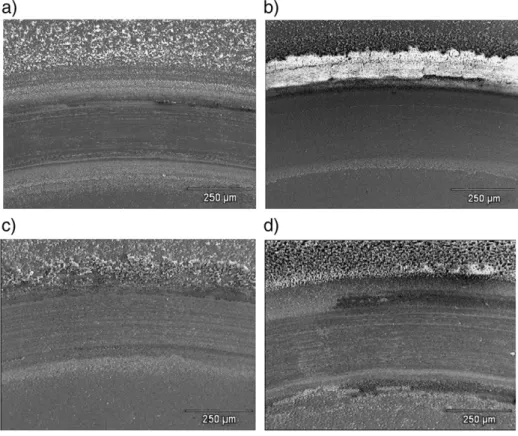
Fig. 3illustrates the characteristic morphological features of the
wear tracks determined by SEM analysis corresponding to the steel substrate, whose friction coefficients were reported previously in
Fig. 2. In general, it is observed that a higher quantity of debris is
produced when the substrate is immersed in the NaCl solution than in the SBF solution and their amount increases with the applied load. These results are expected taking into account the pH value of the media, since the presence of a more acidic solution, i.e. a smaller pH, will promote the pitting phenomena characteristic of this kind of materials. Moreover, it has been reported[15] that the inorganic ions such as HPO42−and H2PO4−present in the composition of the SBF solution, could be adsorbed on the steel surface, decreasing the interaction between the passivefilm and the corrosive solution and delaying the pitting initiation[19].
The typical friction behavior of the coated samples under the con-ditions tested in this work is shown inFig. 4. It can be observed that the friction coefficient for the samples tested employing a 2 N normal load shows values of 0.08 and 0.09 for the NaCl and SBF, respectively. Some small events take place, as indicated in curve C corresponding to the coated sample in the presence of the SBF solution, which could be attributed to the interaction of the liquid under this load with the coating defects, producing locally a higher amount of debris.
Fig. 1. SEM micrograph, indicating the morphology of the a-C:H coating on 316L stain-less steel.
In both cases, the coatings have been worn due to the interaction with the alumina ball, but have maintained their adherence to the substrate without spalling or delamination. However, the friction co-efficients exhibited by the coated samples under a normal load of 5 N are considerably higher and the events taking place during the friction evolution curve with the sliding distance indicate that coating failure has occurred starting from thefirst meters of sliding for the sample A and around 400 m for the sample B.
This difference in behavior could be attributed to the aggressiveness of the solution, which contains K ions, results that corroborate the experimentalfindings reported by Novikov et al.[13]. These authors have suggested that the highest destabilization of carbon bonds occurs 0.00 0.20 0.40 0.60 0.80 0 200 400 600 800 1000 1200 Friction Coefficient Sliding Distance, m 3.5% NaCl SBF 0.00 0.20 0.40 0.60 0.80 0 200 400 600 800 1000 1200 Friction Coefficient Sliding Distance, m 3.5% NaCl SBF
a)
b)
Fig. 2. Friction coefficient vs. sliding distance for 316L stainless steel in the SBF and 3.5% NaCl corrosive solution at a normal load of: (a) 2 N; (b) 5 N.
0.00 0.10 0.20 0.30 0.40 0.50 0.60 0 200 400 600 800 1000 1200 Friction Coefficient Sliding Distance, m A B C D
Fig. 4. Variation of the friction coefficient with the sliding distance for a coated sample tested with a 5 N normal load: (A) in the SBF solution; (B) in the 3.5% NaCl solution; (C) coated sample tested a 2 N normal load in a SBF solution; (D) coated sample tested a 2 N normal load in a 3.5%NaCl solution.
Fig. 3. SEM micrographs of the wear track corresponding to the 316 stainless steel samples tested in: (a) SBF solution at 5 N; (b) 3.5% NaCl solution at 5 N; (c) SBF solution at 2 N; (d) 3.5% NaCl solution at 2 N.
in thefilm's near-surface layer, leading to the destruction of the a-C:H coating mainly in contact with an alkali solution and, especially, when the K ion is present. These authors also claimed that the destruction of the coating was mainly due to the formation of CO and CO2, which took place with the production of a considerable amount of debris. However, in the present work such hypothesis has not been confirmed. At a sliding distance of around 240 m, the coating is completely worn out and the friction coefficient reaches a steady state value of 0.38 at the end of the test, similar to the value found in the contact steel/alumina ball at a 5 N applied normal load.
However, in the case of the coated sample tested at 5 N in the presence of NaCl, it is interesting to mention the fact that even after 1000 m of sliding distance, the recorded friction coefficient value of 0.26 is less than 0.54 that was reported previously in
Fig. 2b, a value that was determined for the tribocouple 316L
stain-less steel/alumina ball. This response indicates that a new surface was formed during sliding, where the delaminated coating was pushed by the sliding ball in the soft steel substrate, leading to a much harder surface than for the above mentioned tribocouple.
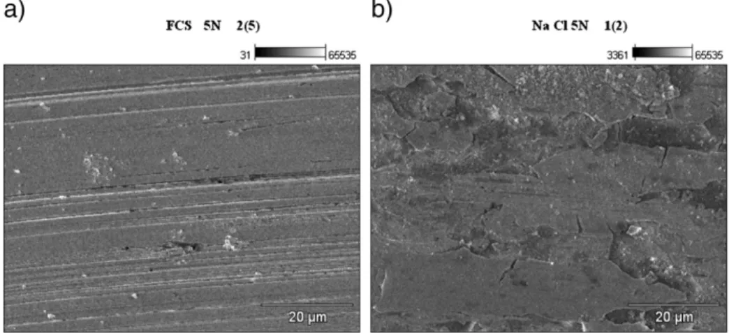
Fig. 5a and b shows the morphological characteristics of the worn
coated surface, indicating the presence of abrasive features produced as a consequence of the differences between the hardness of the two counterparts.
As it can be observed, in the case of the sample immersed in the 3.5% NaCl solution (seeFig. 5b), the fracture of the coating has taken place and some parts have been embedded in the substrate, giving rise to a new surface with different tribological characteristics.
The 2D and 3D profiles obtained by means of the optical profilometer of the wear tracks for all the coated systems tested under the experi-mental setting described previously are shown inFig. 6.
FromFig. 6it can be clearly observed that when the normal load
employed corresponds to the lower value of 2 N, the coatings are still present on the stainless steel substrate and, therefore, the value of the intrinsic rate constant can be calculated by dividing the wear volume by the product between normal load and the sliding distance
(seeTable 1).
However, the wear track profile corresponding to the sample tested in the SBF solution has an irregular shape, which makes the evaluation of the cross sectional area with the same precision as for the sample im-mersed in the NaCl solution difficult. Nevertheless, it was found that the value of the wear constant, k, was of approximately 2 × 10⁻⁶mm3/Nm and no significant differences were obtained between the wear rate of the DLC coating in 3.5% NaCl and the SBF solution, respectively.
As shown inFig. 3, at a higher load of 5 N the depth and width of the wear tracks are much larger when compared with the wear tracks obtained for a load of 2 N. In this case, it was easier to determine the
wear volume with a higher precision, since the effect of the SBF solution was amplified by the application of the normal load. Nevertheless, in both solutions, the coating was worn out, leaving part of the substrate in contact with them. Therefore, contrary to the experiments conducted with a normal load of 2 N, it was not possible to assess the intrinsic wear coefficients of the coatings and only the wear volumes are reported (see
Table 1).
It is interesting to mention here the fact that, for the system im-mersed in NaCl solution, the presence of the coating has changed the expected behavior of the substrate in this type of solution (seeFig. 3) since the high amount of wear debris resulted from the action of the NaCl solution in contact with bare steel has been considerably dimin-ished, as consequence of the creation of a totally new surface, which exhibits a higher resistance to corrosive wear (seeFigs. 4 and 5b).
It can be seen that the wear volume of the coated sample tested in the SBF solution is double of the wear volume of the coated sample tested in the NaCl solution, as consequence to the aggressiveness of the former solution, as explained above.
3.2. Calculations of von Mises stresses developed at the interface of coating–substrate
At this point, it would be interesting to compare the results obtained in this study with other results reported in the literature for continuous or reciprocating sliding wear tests, which have been carried out to determine the behavior of a-C:H coatings in corrosive solutions (water or NaCl), using alumina, sapphire or WC–Co, as counterparts. These include the work of Liu et al.[20], Mohrbacher and Celis[21], Ronkainen et al.[22], Yi et al.[12], Azzi et al.[10], Stallard et al.
[23], Manhabosco et al.[24]and Park et al.[15], for different systems involving DLC coatings. Particularly, the work of Liu et al.[20] repre-sents an example of the behavior of a coating similar to the one employed in the present study, tested in 85% humid environment.
For this purpose, it is necessary to know the elastic properties of the tribological pairs involved in these experiments and the geometrical characteristics of the counterpart, which will allow the calculation of the maximum Hertzian contact pressure and contact radius, as well as the change in the von Mises stress with the distance from the coating surface for every normal load employed.
As pointed out by Drees et al.[25], the stresses developed during the contact are much higher when the test is carried out in an aqueous media than in air as a consequence of the lack of the transfer layer, which normally contributes to their considerable decrease.
Table 2presents all the data needed for the calculations. This
in-cludes the thickness and elastic properties of the coatings, elastic properties and yield strength of the substrate, as well as diameter
Fig. 5. SEM micrographs corresponding to the morphology of the center of the wear tracks of the coated samples for the load of 5 N: (a) sample immersed in the SBF solution in-dicating the presence of some abrasive features on the bare steel surface and showing the coating absence. The white particles correspond to the alumina debris from the ball; (b) sample immersed in the 3.5% NaCl, where the fractured coating is still present and some parts have been embedded into the substrate surface.
and elastic properties of the counterpart, normal load applied to the coated system and its response during testing in the corresponding corrosive solution.
The mechanical behavior of the systems was evaluated by carrying out the analytical calculation of the elastic contact deformationfield under a spherical indenter, for the case of a Hertzian contact condi-tion, by means of the software ELASTICA©.Table 3summarizes the values determined for the contact radius, maximum Hertzian contact pressure for each tribosystem and the calculated values of the von Mises stress both in the coating and in the substrate at the interface.
Fig. 7illustrates the results of these calculations, where the variation
of the von Mises stress with distance from the surface is indicated for each system. In general, with the exception of curve i corresponding
to the work of Park et al.[15], as the distance from the surface increases, the stress also increases smoothly within the coating up to the interface. At this location one or two discontinuities can be observed, depending on the presence of a bonding interlayer between the substrate and coat-ing. At these interfaces the stress decreases abruptly. Once the substrate is achieved, the stress continues to rise as the distance from the surface increases. Thus, a maximum stress value is achieved, after which the stress starts to decrease. In the case of curve i, it can be observed that the stress decreases smoothly within the coating and rises abruptly at the interface, after which it exhibits the same trend found for the other curves. The different coated systems have been identified with a corresponding letter both inTables 2 and 3. A dotted line indicating a stress of 370 MPa is also included in the plot, which indicates the
Profiles 3D
Profiles 2D
a)
b)
c)
d)
Fig. 6. Profiles of the wear tracks corresponding to the DLC coating tested in: (a) SBF solution at 2 N; (b) SBF solution at 5 N; (c) 3.5% NaCl solution at 2 N; (d) 3.5% NaCl solution at 5 N.
Table 1
Wear volume and wear constant of the systems under study.
Load (N) Solution Distance (m) Cross sectional area of the wear track (mm2
) Wear Volume (mm3
) k (mm3
/Nm) S.D.
2 NaCl 1000 0.00024 0.0049 ± 0.001 2.3E−06 2.2E−07
DLC 2 SBF 1000 0.00016 0.0038 ± 0.001 1.8E−06 3.7E−07
5 NaCl 1000 0.00093 0.018 ± 0.003
threshold stress value from which coating spallation was observed, as explained in the forthcoming.
Fig. 8, on the other hand, illustrates the stress distribution curves
only for the coated systems whose substrate is 316L stainless steel.
FromTable 3andFig. 8, it can be observed that for the coated systems
investigated in the present work (corresponding to curves a and b in
Fig. 8), as well as in those studied by Yi et al.[12](curve e) and Azzi et
al.[10](curve f), the substrate yield strength is approximately equal to 530 MPa. These coated systems should behave similarly, given the fact that the maximum values of the von Mises stress computed for each system exceed the yield strength of the substrate for all the normal loads used.
However, it should also be borne in mind that below the coating, the existence of a 316L stainless steel layer could provide an elastic support to it. For example, for curves a and b inFig. 7, corresponding to the tests conducted in the present research, it can be seen that when a normal load of 2 N is applied (curve a), the thickness of the elastic layer, of about 8.3μm, is approximately 4 times the thickness of the coating and decreases to 5.5μm for a load of 5 N (curve b). Consequently, it will be expected that plastic deformation of the substrate occurs at a distance from the surface greater than approximately 3μm (curve f) and that during a wear test carried out in air, for both values of the applied load, no cracking will occur that could give rise to the coating detachment.
Conversely, for the system investigated by Stallard et al.[23], in which the substrate is a M42 steel whose yield strength is 2.4 GPa (curve g inFig. 7), it is expected that the deformation of the substrate will not take place and that the coating will maintain its integrity.
Nevertheless, in the presence of water or a sodium chloride solu-tion the results are totally different from what should have been expected if the tests would have been carried out in dry air.
It is well known that the effect of the environment on the tribological response of these coatings has not been yet completely elucidated. For ex-ample, Li et al.[26]investigated the effects of various environments on an a-C:H coating by conducting XPS analysis of the worn surfaces. They indi-cated that in water and/or oxygen containing environments, the oxida-tion of the a-C:Hfilms took place with the destruction of the C:H bonds and the production of new bonds with oxygen-containing groups, which led to an increases of the friction coefficient and the wear rate.
In the present work, as indicated inTable 3, it has been shown that when the tests are carried out using a load of 5 N, the coating immersed in the SBF solution undergoes spallation long before in comparison with the tests conducted in the NaCl solution, exhibiting a higher friction coefficient of 0.38 as compared to 0.26 for the latter solution. This be-havior has been explained earlier by taking into account the chemical nature of the ions present in each solution accompanied by the rapid penetration of the solution at the coating–substrate interface, as a con-sequence of the coating fracture.
However, for the case in which the tests were performed using a load of 2 N, for which the shearing action of the frictional force is small-er, it was observed that the friction coefficient had a much lower constant value, irrespective of the solution employed during the tests (i.e. about 0.08 for NaCl and slightly higher than 0.09 for the SBF, respec-tively). The fact that for an applied load of 2 N the friction coefficient re-mains considerably constant and has a similar magnitude for both solutions employed, indicates that the stress state to which the coated system is subjected plays an important role in the response of this sys-tem when it is in contact with the corrosive media.
As can be seen inFig. 7, the state of stress for the coated system under a load of 5 N (curve b) is more severe than in the case of a 2 N load (curve a). Therefore, it could be argued that its severity enhances the corrosive action of the solutions, similarly to the commonly ob-served stress corrosion-cracking phenomenon.
Thus, from the plot of the variation of the von Mises stress with distance from the surface for all the systems reported inFig. 7and considering the values of this stress that corresponds to the coating
Table 2 The mechanical characteristics of the system under study and other similar coated systems reported in the literature tested under corrosive environ ments. TEST Present work Liu et al. [20] Mohrbacher and Celis [21] Ronkainen et al. [22] Yi et al. [12] Azzi et al. [10] Stallard et al. [23] Manhabosco et al. [24] Park et al. [15] ab c d e f g h i System a-C:H (40%H)/CrC interlayer/316L steel a-C:H (40%H)/CrC interlayer/316L steel a-C:H (30%H)/M2 steel a-C:H (20 – 40%H)/ Si interlayer/440B steel a-C:H/Si interlayer/ 316 steel a-C:H/SiNx interlayer/ 316L steel ⁎ a-C:H (40%)/CrC interlayer/M42 steel a-C:H (20%H)/ Ti6Al4V alloy
a-C:H/Si interlayer/ Ti6Al4V
alloy Coating Thickness (μ m) 2.2 2.2 2 1.7 1 0.65/0.35 2 4 1 E (GPa) 145 145 200 [25] 200 200 140/160 145 146 200 ν 0.3 0.3 0.3 0.25 0.25 0.3 0.3 0.3 0.3 Substrate E(GPa) 210 210 228 200 210 210 210 110 110 ν 0.3 0.3 0.3 0.3 0.3 0.3 0.3 0.34 0.34 Yield strength (GPa) 0.530 0.530 2.2 1.7 0.530 0.530 2.4 0.83 0.83 Counterpart Diameter o f the b al l Φ = 6 mm alumina Φ = 6 mm alumina Φ = 10 mm corundum Φ = 10 mm alumina Φ =6m m sapphire Φ = 4.75 alumina Φ = 5 mm WC – 6%Co Φ =5m m alumina Φ =6m m sapphire E (GPa) 360 360 310 [19] 360 345 360 630 350 345 ν 0.2 0.2 0.27 [19] 0.2 0.2 0.2 0.2 0.2 0.2 Normal load (N) 2 5 2 5 4 9 5 16 5.9 Response of the coated system No spallation in 3.5%NaCl solution Spallation in 3.5%NaCl solution No failure in 85% humidity No spallation in water Spallation in water Spallation in Ringer Solution Spallation in water Spallation in PBS solution No spallation in water ⁎Calculations were conducted for 2 layers coating.
and substrate at the interface indicated inTable 3, it can be concluded that in those systems where the stress in the coating found in the vicinity of the interface exceeds a threshold value of the von Mises stress of approximately 370 MPa, coating failure with spallation will take place, regardless of the substrate nature on which this coating was deposited.
A plausible mechanism for explaining the failure of the investigated coated systems, when this threshold stress value is achieved, could be the attainment of a critical stress intensity for the nucleation and propa-gation of cracks in the DLC coatings. The work conducted by Xie et al.[6]
showed that when DLC coatings are subjected to indentation loads, ring cracks developed when a critical indentation load was achieved, which allowed the computation of the fracture toughness of the coating. These authors clearly showed by means of combined indentation, scratching and FIB analysis that under indentation loads, lateral cracking occurs at the coating–substrate interface and that the nucleation and propagation of ring and radial cracks are the main mechanism for the coating fracture. Thus, taking into consideration the geometrical
characteristics of the counterparts employed in the different experi-ments whose results have been analyzed in the present work, it could be possible to rationalize that a threshold stress value of approximately 370 MPa could lead to a critical stress intensity greater than the fracture toughness of the coating, giving rise to the nucleation and growth of ring and radial cracks. Thus, as indicated by Ohana et al.[27], once these cracks are formed, either water or a chloride solution can easily pene-trate through them, which would be a much easier path towards the sub-strate in comparison of the path offered by the coating defects, thus compromising the stability of the coated system and giving rise to the coating failure.
From this analysis, it is apparent that the intrinsic mechanical properties of the coating itself are of utmost importance in conferring the a-C:H coated system the required stability in a corrosive solution and apparently even more important than the load carrying support of the coating.
Table 3
Results from the analytical calculations of the elastic contact deformationfields under a spherical indenter for the cases of Hertzian contact conditions. TEST Present work Liu et al.[26]
Mohrbacher and Celis[21] Ronkeinen et al. [22]2001-1998 Yi et al. [12]
Azzi et al.[10] Stallard et al.[23] Monhabosco et al.[24] Park et al.[15] a b c d e f g h i System a-C:H (40%H)/ CrC interlayer/ 316L steel a-C:H (40%H)/CrC interlayer/316L steel a-C:H/M2 steel (30%) a-C:H(20-40%H)/ Si interlayer/440B steel a-C:H /Si interlayer/ 316 steel a-C:H/SiNx interlayer/ 316L steel⁎ a-C:H(40%)/CrC interlayer/M42 steel a-C:H (20%H)/ Ti6Al4V alloy a-C:H/Si interlayer/ Ti6Al4V alloy Normal load, (N) 2 5 2 5 4 9 10 16 5.9 a, Contact radius (μm) 31.5 43 37.2 51.4 40.1 50.3 47.5 68.7 52.4 Max.contact pressure (GPa) 0.96 1.30 0.7 0.9 1.2 1.7 2.1 1.62 1.02 σmaxat distance x
from the surface (GPa) 0.6 at 15.5μm 0.8 at 21μm 0.43 at 18μm 0.56 at 25μm 0.74 at 19.5μm 1.07 at 24.6μm 1.32 at 23.2μm 1.01 at 32.5μm 0.64 at 24.7μm σcoatingGPa) 0.360 0.479 0.2 0.331 0.433 0.760 0.514 0.383 0.160 σsubstrate(GPa) 0.294 0.364 0.195 0.227 0.279 0.560 0.370 0.520 0.259 Response of the coated system No spallation in 3.5% NaCl solution Spallation in 3.5% NaCl solution No spallation In 85 % humidity No spallation in water Spallation in water Spallation in water Spallation in Ringer Solution Spallation in PBS solution No spallation in water ⁎ Calculations were conducted for two layers coating.
0 200 400 600 800 1000 1200 1400 100 10 1 0.1 g f h b e i d a c
Von MisesStress, MPa
Distance from the surface, µm
Threshold Stress for Coating Spallation
Fig. 7. Variation of the von Mises stress with the distance from the surface for the sys-tems under study and for other DLC coated syssys-tems reported in the literature and de-scribed inTable 2. 0 200 400 600 800 1000 1200 1400 0.1 1 10 100 f b e a 316L SS yield strength
Von Misesstress, MPa
Distance from the surface, µm
Fig. 8. Stress distribution curves for the coated systems whose substrate is 316L stainless steel: curve a (wear test carried out in 3.5% NaCl solution at 2 N normal load—present work); curve b (wear test carried out in 3.5% NaCl solution at 5 N normal load—present work); curve e (wear test carried out in water at 4 N normal load—Yi et al.[12]); curve f (wear test carried out in Ringer solution and 9 N normal load—Azzi et al.[10]). Dotted line corresponds to the substrate yield strength of 530 MPa.
As it has been mentioned in the literature, such a load-carrying capa-bility, which is determined by the relationship between the substrate and the coating Young modulus values, could have a significant influence either on the magnitude of the stresses developed at thefilm–substrate interface[28]or on the mechanisms responsible for coating delamination. However, as reported by Borrero-López et al.[7], such a relationship is not directly related with the processes starting at the substrate–coating interface.
The supposition of the existence of a threshold stress value related to the intrinsic mechanical properties of the coating is supported by a recent investigation carried out by Kuzumaki et al.[29]who reported some results related to the tensile strength values corresponding to a DLC coat-ing of approximately 1μm in thickness, deposited on a tungsten substrate by means of a pulsed plasma CVD method. These authors were able to peel off the DLC coatings and determine its tensile stress–strain curve by means of a nanomaterial tester located inside a scanning electron mi-croscope. Their results indicate that under these deformation conditions, the material exhibits a brittle fracture behavior and thatfinal fracture oc-curs at a strain of the order of 0.4% and a stress of approximately 420 MPa. Also, it is important to mention that the hardness determined for thisfilm was reported to be in the range of 12–20 GPa. These are remarkable results, which point out the fact that the fracture strength of this kind of materials cannot be simply assessed by applying Tabor's rule, according to which the expected strength of the film would be in the range of 4–7 GPa.
The threshold stress value determined in the present work for the occurrence offilm spallation is somewhat less than the fracture strength reported by Kuzumaki et al.[29]. However, such a difference could be attributable not only to the distinct deposition processes employed in the synthesis of the substrate–coating systems under in-vestigation, but also to the fact that the present stress analysis considers that such systems are subjected to different deformation conditions. 4. Conclusions
The influence of two corrosive solutions (simulated body fluid and 3.5 wt.% NaCl solution) on the tribological behavior of an a:C-H coating, deposited onto a 316L stainless steel, has been investigated. From the experiments carried out in the present work it can be concluded that, from the tribological point of view, the coated systems behave better in the NaCl solution than in the SBF solution, contrary to the bare substrate, whose behavior has been found to be better in the SBF solution. For the stainless steel uncoated substrate–alumina ball tribosystem the friction coefficient values were higher in the 3.5% NaCl solution in comparison with that found in the SBF solution, regardless of the normal load employed during the wear tests.
The profiles of the wear tracks corresponding to the worn coated sam-ples in both solutions employed in the present work, when using a nor-mal load of 2 N, indicated that the coating was still present on the stainless steel substrate and that the wear constant value determined was of an order of 10−6mm3/Nm. However, at a higher load of 5 N, spall-ation of the coating took place and the wear volume of the sample tested in the SBF solution was twice as much the wear volume of the sample tested in the NaCl solution. This difference in behavior was attributed to the aggressiveness of the alkaline solution, which contained K ions, contributing to the destruction of the a-C:H coating, accompanied by the production of a considerable amount of debris, as shown in the SEM micrographs of the worn coated samples.
The results obtained from the calculations of the von Mises stresses developed at the coating–substrate interface during the static contact be-tween the ball and the samples, both for the experiments conducted in the present research, as well as those reported from previous research work published in the literature, indicate the existence of a threshold stress value for the occurrence of coating spallation. Thus, in those systems where the stress in the coating, found in the vicinity of the inter-face, exceeds approximately 370 MPa, coating failure with spallation will
take place, regardless of the substrate nature on which this coating was deposited.
The threshold stress value determined in the present work for the oc-currence offilm spallation is somewhat less than the fracture strength re-ported by Kuzumaki et al.[29]. However, such a difference could be attributed not only to the distinct deposition processes employed in the synthesis of the substrate–coating systems under investigation, but also to the fact that the present stress analysis considers that such systems are subjected to different deformation conditions.
From this analysis it has been concluded that the coating yield strength is of utmost importance in conferring the a-C:H coated system the required stability in a corrosive solution. Therefore, thesefindings are consistent with the wear test results of the DLC coating under study and could rationalize quite satisfactorily the difference observed as a function of the test parameters, such as normal load and corrosive media. Prime novelty statement
From the tribological point of view it has been shown that the coated systems behave better in the NaCl solution than in the SBF solution, con-trary to the bare substrate, whose behavior has been found to be better in the SBF solution. In order to interpret the results, calculations of the values of the von Mises stresses developed at the coating–substrate interface, as soon as the ball touches the coated sample, and how this state of stress in-fluences the response of the coated system under the corrosion environ-ment, have been performed for thefirst time for this kind of systems. It has been determined that in those systems, where the von Mises stress in the coating, found in the vicinity of the interface, exceeds the threshold value of approximately 370 MPa, coating failure with spallation will take place, regardless of the substrate nature on which this coating was depos-ited. The existence of a threshold stress value was related to the intrinsic mechanical properties of the coating. Thus, it could be possible to ratio-nalize that the above threshold stress value could lead to a critical stress intensity greater than the fracture toughness of the coating, giving rise to the nucleation and growth of ring and radial cracks. These cracks con-stitute a much easier path of the solution towards the substrate in com-parison of the path offered by the coating defects, thus compromising the stability of the coated system and giving rise to the coating failure. Acknowledgments
Professor Staia acknowledges thefinancial support from CDCH-UCV, Venezuela through the project No. AIB-08-8539-2012 and MSMP, Arts et Métiers ParisTech (ENSAM Lille), France. Professor Puchi-Cabrera gratefully acknowledges the financial support of the Conseil Régional Nord-Pas de Calais, France, through the International Chair program 2011. Dr. Santana acknowledges thefinancial support from CDCH-UCV project no. PI-08-7824-2009/1. The authors thank D. Lugo for carrying out the wear tests in CENMACOR-UCV (Venezuela). References
[1] A. Erdemir, C. Donnet, Tribology of diamond-like carbonfilms: recent progress
and future prospects, J. Phys. D: Appl. Phys. 39 (2006) R311–R327.
[2] C.A. Love, R.B. Cook, T.J. Harvey, P.A. Dearnley, R.J.K. Wood, Diamond like carbon
coat-ings for potential application in biological implants—a review, Tribol. Int. 63 (2013) 141–150.
[3] C.V. Falub, U. Muller, G. Thorwarth, M. Parlinska-Wojtan, C. Voisard, R. Hauert, In
vitro studies of the adhesion of diamond-like carbon thinfilms on CoCrMo
biomedical implant alloy, Acta Mater. 59 (2011) 4678–4689.
[4] L. Chandra, M. Allen, R. Butter, N. Rushton, A.H. Lettington, T.W. Clyne, The effect
of biologicalfluids on the adhesion of diamond-like carbon films to metallic
substrates, Diam. Relat. Mater. 4 (1995) 852–856.
[5] S.J. Park, K.-R. Lee, S.-H. Ahn, J.-G. Kim, Instability of diamond-like carbon (DLC)
films during sliding in aqueous environment, Diam. Relat. Mater. 17 (2008) 247–251.
[6] Z.-H. Xie, R. Singh, A. Bendavid, P.J. Martin, P.R. Munroe, M. Hoffman, Contact
damage evolution in a diamond-like carbon (DLC) coating on a stainless steel substrate, Thin Solid Films 515 (2007) 3196–3201.
[7] O. Borrero-López, M. Hoffman, A. Bendavid, P.J. Martin, Substrate effects on the
mechanical properties and contact damage of diamond-like carbon thinfilms,
Diam. Relat. Mater. 19 (2010) 1273–1280.
[8] S.J. Bull, Tribology of carbon coatings: DLC, diamond and beyond, Diam. Relat.
Mater. 4 (1995) 827–836.
[9] A. Suzuki, Y. Aiyama, M. Tokoro, H. Sekiguchi, M. Masuko, Friction and wear
char-acteristics of hydrogenated diamond-like carbonfilms formed on the roughened
stainless steel surface, Wear 269 (2010) 118–124.
[10]M. Azzi, P. Amirault, M. Paquette, J.E. Klemberg-Sapieha, L. Martinu, Corrosion
performance and mechanical stability of 316L/DLC coating system: role of inter-layers, Surf. Coat. Technol. 204 (2010) 3986–3994.
[11]M. Weber, K. Bewilogua, H. Thomsen, R. Wittorf, Influence of different interlayers
and bias voltage on the properties of a-C:H and a-C:H:Me coatings prepared by reactive d.c. magnetron sputtering, Surf. Coat. Technol. 201 (2006) 1576–1582.
[12] J. Woo Yi, S.J. Park, M.-W. Moon, K.-R. Lee, S.-S. Kim, Defect effect on tribological
behavior of diamond-like carbonfilms deposited with hydrogen diluted benzene
gas in aqueous environment, Appl. Surf. Sci. 255 (2009) 7005–7011.
[13]N.V. Novikov, S.I. Khandozhko, V.M. Perevertailo, L.Yu. Ostrovskaya, A.G. Gontar,
O.B. Loginova, The mechanism of destruction of a-C:Hfilms under the action of
aggressive liquids, Diam. Relat. Mater. 9 (2000) 843–846.
[14]N.V. Novikov, S.I. Khandozhko, V.M. Perevertailo, L.Yu. Ostrovskaya, A.G. Gontar,
O.B. Loginova, The wettability of a-C:Hfilms by solution of different
physico-chemical compositions, Diam. Relat. Mater. 7 (1998) 1263–1266.
[15]S.J. Park, K.-R. Lee, D.-H. Ko, Tribochemical reaction of hydrogenated
diamond-like carbonfilms: a clue to understand the environmental dependence,
Tribol. Int. 37 (2004) 913–921.
[16]M. Jarratt, J. Stallard, N.M. Renevier, D.G. Teer, An improved diamond-like carbon
coat-ing with exceptional wear properties, Diam. Relat. Mater. 12 (2003) 1003–1007.
[17]Internal Report— Hydrogen Forward Scattering (HFS) Laboratory Report — EAG
Number C0410486, Evans Analytical Group, March 22 2004.
[18]E.S. Puchi-Cabrera, M.H. Staia, E.A. Ochoa-Pérez, D.G. Teer, Y.Y. Santana, J.G. La
Barbera-Sosa, D. Chicot, J. Lesage, Mater. Sci. Eng. A527 (2010) 498–508.
[19]H. Yang, K. Yang, B. Zhang, Pitting corrosion resistance of La added 316L stainless
steel in simulated bodyfluids, Mater. Lett. 61 (2007) 1154–1157.
[20]E. Liu, Y.F. Ding, L. Li, B. Blanpain, J.-P. Celis, Influence of humidity on the friction
of diamond and diamond-like carbon materials, Tribol. Int. 40 (2007) 216–219.
[21]H. Mohrbacher, J.-P. Celis, Friction mechanisms in hydrogenated amorphous
carbon coatings, Diam. Relat. Mater. 4 (1995) 1267–1270.
[22]H. Ronkainen, S. Varjus, K. Holmberg, Tribological performance of different DLC
coatings in water-lubricated conditions, Wear 249 (2001) 267–271.
[23]J. Stallard, D. Mercs, M. Jarratt, D.G. Teer, P.H. Shipway, A study of the tribological
behaviour of three carbon-based coatings, tested in air, water and oil environ-ments at high loads, Surf. Coat. Technol. 177–178 (2004) 545–551.
[24]T.M. Manhabosco, A.P.M. Barboza, R.J.C. Batista, B.R.A. Neves, I.L. Müller,
Corro-sion, wear and wear–corrosion behavior of graphite-like a-C:H films deposited on bare and nitrided titanium alloy, Diam. Relat. Mater. 31 (2013) 58–64.
[25]D. Drees, J.P. Celis, E. Dekempeneer, J. Meneve, The electrochemical and wear
behavior of amorphous diamond-like carbon coatings and multilayered coatings in aqueous environments, Surf. Coat. Technol. 86–87 (1996) 575–580.
[26]H. Li, T. Xu, C. Wang, J. Chen, H. Zhou, H. Liu, Tribochemical effects on the friction
and wear behaviors of a-C:H and a-Cfilms in different environment, Tribol. Int. 40
(2007) 132–138.
[27]T. Ohana, T. Nakamura, M. Suzuki, A. Tanaka, Y. Koga, Tribological properties and
characterization of DLCfilms deposited by pulsed bias CVD, Diam. Relat. Mater. 13
(2004) 1500–1504.
[28]S. Ramalingam, L. Zheng, Film-substrate interface stresses and their role in
the tribological performance of surface coatings, Tribol. Int. 28 (3) (1995) 145–161.
[29]T. Kuzumaki, Y. Obara, Y. Ishiyama, R. Sato, M. Takashima, N. Ohtake, Diam. Relat.