Science Arts & Métiers (SAM)
is an open access repository that collects the work of Arts et Métiers Institute of Technology researchers and makes it freely available over the web where possible.
This is an author-deposited version published in: https://sam.ensam.eu
Handle ID: .http://hdl.handle.net/10985/6798
To cite this version :
Mohamed ACHOURI, Guénaël GERMAIN, Philippe DAL SANTO, Delphine SAIDANE -Implementation and validation of a Gurson damage model modified for shear loading: effect of void growth rate and mesh size on the predicted behavior - In: Material Forming ESAFORM 2012, Afghanistan, 2012-02 - Key Engineering Materials - 2012
Any correspondence concerning this service should be sent to the repository Administrator : archiveouverte@ensam.eu
Implementation and validation of a Gurson damage model modified for
shear loading: effect of void growth rate and mesh size on the predicted
behavior
Mohamed Achouri
1, a, Guenael Germain
1, b,
Philippe Dal Santo
1, c,
and Delphine Saidane
2, d1
LAMPA (EA 1427), 2 Boulevard du Ronceray BP 93525, 49035 Angers-France
2DEVILLE SA, ZI de Beauregard 49150 Baugé-France
aMohamed.Achouri@ensam.eu, bGuenael.Germain@ensam.eu, cPhilippe.DalSanto@ensam.eu, ddelphine.saidane@devillesa.fr
Keywords: Damage- Gurson Model– Shear – Fracture - Numerical Simulation
Abstract. The optimization of automotive security components requires good knowledge of the
material state after fabrication, particularly with respect to damage that may have been done to the material by the manufacturing process. To achieve this, numerical simulation of the fabrication process is often undertaken. However, classical continuum damage models, like the Gurson [3] model, are not appropriate for the simulation of the blanking by punching operation because the material damage is primarily the result of shear stresses. This work is focused on the use and validation of a modified Gurson type damage model capable of modeling this process, which has recently been proposed by Nahshan [7]. After a brief description of the modification, the implementation and the validation of the modified Gurson model is detailed. A comparison between the original Gurson model and the modified model is presented in order to highlight the importance of the modification for a pure shear stress state and to show that the two models are equivalent for a purely hydrostatic stress state. It is also shown that the results from the modified model are dependent on the finite element mesh size.
Introduction
Thanks to their good mechanical properties HSLA steel sheets are widely used for the manufacturing of automotive components. In some forming processes, such as blanking, ductile fracture of these materials is caused by damage occurring in the form of localized shear strain. In a classical sense ductile fracture is a result of a gradual change in the material that occurs during plastic deformation, which is usually characterized by the nucleation and growth of cavities or voids and their subsequent coalescence to form cracks. A great deal of work has been done concerning ductile failure modes with high tri-axiality. The fundaental analysis was begun by McClintock [1]
and later by Rice and Tracey [2] who studied the evolution of cylindrical and spherical cavities in a ductile matrix. Gurson [3] proposed a model based on a micromechanical approach. This model describes the growth of spherical cavities and its influence on the material behavior. The Gurson model was later modified by Tevergaard and Needleman [4] by adding a mechanism to describe ductile fracture by nucleation, growth and coalescence of spherical cavities. This is generally referred to as the GTN model. Improvements to the GTN model have been made in terms of hardening by Leblond [5]. The effect of cavity shape has been investigated by Grange [6] and Benzarga [12] has included plastic anisotropy. The basic formulation of the Gurson model is unable to predict location and rupture for shear dominated stress states as found in the blanking by punching process. Recent extensions to the Gurson model have been proposed by Nahshan [7] to take into account the accumulation of effective damage caused by the distortion of cavities and the inter-cavity interaction due to shear strain, as observed in a previous study [8].
In the first part of this paper the extension to the Gurson model proposed by Nahshan is presented. In the second part, the implementation of this model in the ABAQUS® [9] commercial finite element code is described. The implementation is subsequently verified to check the algorithm and to illustrate the effect of growth and rotation rate on cavities or voids loaded in shear. The results from a numerical tensile test are then presented to analyze the effect of mesh size on the material behavior.
Description of the ductile damage model modified for shear The yield surface. The yield surface is given by:
2 * 2 *2 1 3 0 0 3 ( , ) 2 cosh 1 0 2 q p q q p q f q f (1)Where q1, q2 and q3 are the constitutive parameters proposed by Tevergaard [4],
3 2 ij ij
q S S is
the Von Mises equivalent stress, 1
3 ij ij ij ij
S is the deviatoric stress tensor, 1
3 kk
p is the hydrostatic stress, and σ0 is the flow stress of the undamaged material matrix, given by the Ludwick
law: 0 yK(p)n, where n is the hardening exponent and K is a material parameter.
The function f* represents the increase in the void volume fraction due to coalescence. This function is given by [4]: { ( ) , √ (2)
Where fc is the critical void volume fraction for which coalescence begins, and ff is the void
volume fraction at rupture.
Void growth rate. The new expression for the void volume fraction growth rate ̇ is given by Nahshan [7] as:
̇ ( ) ̇ ( )
̇
(3)
Where ( ) is determined by:
( ) (
) (4)
̇ is the sum of the diagonal of the strain rate tensor and is the third invariant of the deviatoric stress tensor (J3=det(s)). For axisymmetric stress states combined with a hydrostatic
component, w is equal to zero and this model is equivalent the original Guson model. However, for shear stress states with a hydrostatic stress component, w is equal to 1.0. The constant kw in
equation (3) is a material parameter that defines the amplitude of the damage growth rate due to
shear. The evolution of the void volume fraction is: ̇ ̇ ̇ (5) Where ̇ ̅̇ represents nucleation, and
√ (
̅
) (6) fN is the void volume fraction created by nucleation, εN is the average plastic strain for which
nucleation is a maximum and SN is the standard deviation of the distribution of nucleated voids with
respect to the plastic strain.
The modified Gurson model has been implemented in ABAQUS/Explicit [9] by using a VUMAT subroutine coupled with an implicit stress integration scheme proposed by Aravas and Zhang [10,11]. The procedure includes two principal steps: an elastic prediction followed by a plastic correction. The total strain is divided into elastic and plastic parts: . The plastic strain increment is further divided into spherical and deviatoric parts:
,
where and . is the plastic multiplier. The volume fraction f and the equivalent plastic strain of the matrix ̅ are treated as being two scalar internal variables, H1 and H2. The implementation procedure can be described by the following steps:
1- Initialize the variables at time t=0: , where are state variables,
2- Determine the elastic predictor by assuming that the strain increment is purely elastic:
, where C is the isotropic linear elastic forth order stiffness tensor,
3- Calculate the hydrostatic stress:
4- Calculate the equivalent von Mises stress: √
5- Determine la yield surface:
(
) ( ) ,
a. If , the current state is elastic,
, hence go to step 7.
b. If , the current state is plastic, hence go to step 6 for the plastic correction,
6- Determine the plastic correction by using the Newton-Raphson iterative method to resolve the following non-linear equations:
( ) ( ) (7) ( ( )) (8)
The flow rule and the condition that the stress state must remain on the yield surface are simultaneously satisfied. The consistency condition (Eq. 9) must also be satisfied at the same time.
( )
̅ ̅
( ) (9)
Iteration is continued until | | and | | are less than a specified tolerance (1.0E-05), which indicates that convergence using the Newton-Raphson method has been achieved. On convergence, go to the following step.
7- Update p, q et : {
(10)
Where ( ) is the shear modulus and ( ) is the compressibility modulus. E and ν are the Young’s modulus and the Poisson’s ratio of the material.
(11) { ̅ ( ) ( ) ( ) ̅ (12) { ̅ ̅ ( ) ̅ ( ) (13) Validation
In the following, simple FE models using only one 3D finite element (see Figure 1) have been undertaken in order to validate the implementation of the modified Gurson model.
Firstly, the simulation of a hydrostatic tensile stress state (see Figure 1(a)) has been done in order to verify the equivalence between the modified model and the original Gurson model. These two models should give the same results for this type of loading condition. A simple shear stress loading
condition (see Figure 1(b)) is then presented in order to highlight the difference between the modified model and the original Gurson model. The results have been compared to the analytical solution in order to demonstrate the relevance of the results.
Figure 1: Boundary conditions and nodal loads for the 2 loading conditions tested: (a) Hydrostatic tension, (b) shear stress
Validation: Hydrostatic Tension. The validation was done using a single cube shaped element of
size 1x1x1mm. The material has an initial yield strength of , a Young’s modulus of , and a Poisson’s ratio of . The plastic behavior is given by: ( ̅ ) . The following constitutive parameters of the model are used: . The
initial volume fraction is set to . The parameters related to the void nucleation are chosen to be: . The critical void volume fraction is and the void volume fraction at rupture is . For this loading condition w is equal to 1.0, hence the results are independent of .
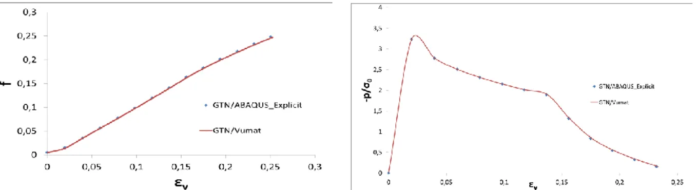
A quadratic element with 8 nodes and reduced integration (C3D8R) has been used to test the hydrostatic tension loading condition. Figure 2 show the evolution of the normalized pressure and void volume fraction as a function of the logarithmic volumetric strain ( ).
Comparisons between the two models have been done with ABAQUS\Explicit using the same input parameters. The evolution of the void volume fraction and the evolution of the hydrostatic pressure have been plotted for the modified Gurson model (VUMAT) and for the original Gurson model (see Figure 2). The curves show that the results of the modified model and the original model are perfectly coincident.
Figure 2: Results of the simulation of a hydrostatic tensile test as a function of the volumetric strain: (a) Hydrostatic pressure and (b) Void volume fraction
Validation: pure shear stress. The same element type has been also loaded in shear by applying
shear forces on the upper nodes in the Y-direction (see Figure 1(b)). The material parameters are identical to those detailed in the previous section, except nucleation is neglected in order to be able to compare the results to an analytical result. In this case, rupture is only due to void growth.
For this loading condition ̇ ̇ and ̇ , hence the effective strain rate is defined by ̇ ̇ √ and the effective stain is given by √ .
Also, for the expression for the evolution of the void volume fraction is ̇ ̇ ̇ . If is the initial void volume fraction, then
With the equation for the yield surface is simplified to: ( ) . Dividing the material hardening law of the matrix by gives:
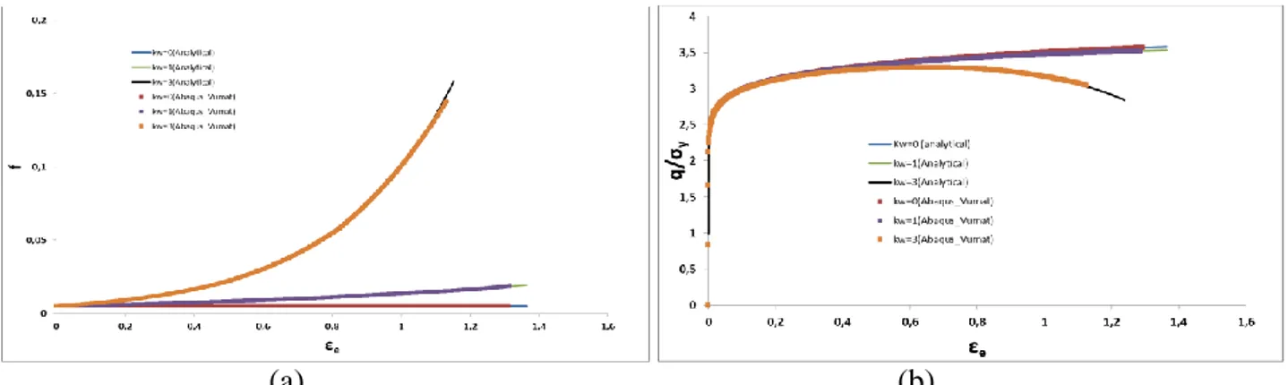
( ) ( ( ) ) (14) Figure 3 shows the evolution of the void volume fraction and the effective stress (or the von Mises equivalent stress, q) as a function of the effective strain for different values of . It can be seen that the numerical predictions and the analytical solutions are in perfect agreement. It can also be seen that an increase of results in a reduction in the strain at which damage localization and rupture commence. In addition, an increase of results in a higher void growth rate. For , the void growth rate in the original Gurson model is zero. This implies that the original Gurson model predicts this loading condition to be non-damaging, which is contrary to experimental observations.
(a) (b)
Figure 3: Results for shear stress simulations as a function of the effective strain: (a) the void volume fraction and (b) the effective stress
Effect of the finite element size
In certain cases, the use of damage and ductile failure laws requires a well refined finite element mesh in order to localize the damaged zones. In such cases, the results are strongly dependant on the mesh size. In this work, an investigation was undertaken in order to determine the optimal mesh size for the implementation of the modified Gerson model. Figure 4(a) shows the FE mesh of a tension specimen using 3D elements (type C3D8R). Only a quarter of the specimen is modeled as the planes of symmetry were exploited to reduce the calculation time. The material behavior is defined by the modified Gursion damage model (q1=1.5, q2=1, q2=2.25, εN=0.3, SN=0.1 et fc=0.15 et
ff=0.25 and kw=2.5), and a Ludwik elasto-plastic law.
Figure 4(b) shows the evolution of the ratio ‘instantaneous force / maximum force’ as a function of displacement for three different mesh sizes. For the three mesh sizes the hardening domain (i.e. before the onset of damage) is basically identical and conforms to the experimental results. However, the mesh size has a significant influence on the end part of the curves that are strongly affected by damage localization. The best results, with respect to the experimental curve, were obtained for a mesh size of 0.25x0.25x0.25mm. This concluded that this mesh size is optimal in terms of hardening, damage and computation time.
(a) (b)
Figure 4: Comparison between the numerical and experimental results from a uniaxial tensile test: (a) Specimen geometry and finite element mesh and (b) the effect of the mesh size on the predicted
force-displacement curves
Conclusion
In this work the modified Gurson ductile rupture model, proposed by Nahshan [7] to better take into account shear stress states, has been implemented in the ABAQUS\Explicit finite element code. This was done via the development of a VUMAT subroutine using an explicit integration algorithm. The implementation has been verified via simple finite element models of a purely triaxial stress state and a pure shear stress state. The results have been compared to the original Gurson model for the first case and to the analytical solution for the second case. The effect of the parameter kw, which represents the damage growth rate in shear, has been investigated. It is concluded that the model is capable of predicting damage localization and rupture for stress states characterized by low stress triaxiality. The effect of the initial finite element size on the results has also been investigated via the simulation of a tensile test. Comparison with the experimentally determined force-displacement curve indicates that mesh size has little influence on the hardening behavior. However, it is shown that the final part of the force-displacement curve is strongly dependant on the mesh size and that the finest mesh gives the best agreement with the experimental result. Increased mesh refinement obviously results in increased calculation times. This modified Gurson model has been implemented in ABAQUS by the authors in order to study sheet metal forming operations like blanking, which are characterized by very high shear stresses and low stress triaxiality. This work is in progress and will be reported in subsequent publications.
References
[1] F.A. McClintock. J. Appl. Mech. Vol. 35 (1968), p. 363–371.
[2] J.R. Rice and D.M. Tracey. J. Mech. Phys. Solids Vol. 17 (1969), p. 201–217. [3] A.L. Gurson. J. Eng. Mater. Technol. Vol. 99 (1977), p. 2–15.
[4] V. Tvergaard, A. Needleman. Acta Metall. Mater., vol.32 (1984), p.157- 169.
[5] J.B. Leblond, G. Perrin, J. Devaux. Eur. J. Mech. A—Solids. Vol. 14(1995), p.499–527. [6] M. Grange, J. Besson, E. Andrieu. Int. J. Fract. Vol. 105 (2000), p. 273–293.
[7] K. Nahshon and J.W. Hutchinson. Eur. J. Mech A Solids. Vol. 27 (2008), p. 1–17.
[8] M. Achouri, G. Germain, P. D. Santo, S. Boude, J. L. Lebrun and D. Saidane. Key Engineering Materials. Vol. 473 (2011), p 460-467.
[9] Abaqus, 2010. Reference Manuals,v 6.10.Abaqus Inc.
[10] N. Aravas, Int. J. Numer. Meth. Eng. Vol. 24 (1987), p. 1395–1416. [11] Z.L. Zhang, Comput. Meth. Appl. Mech. Vol. 121 (1995), p. 29–44.