Science Arts & Métiers (SAM)
is an open access repository that collects the work of Arts et Métiers Institute of Technology researchers and makes it freely available over the web where possible.
This is an author-deposited version published in: https://sam.ensam.eu Handle ID: .http://hdl.handle.net/10985/11354
To cite this version :
JeanYves DIEULOT, Geneviève DAUPHINTANGUY, Lamine CHALAL, Frédéric COLAS -Economic supervisory predictive control of a hybrid power generation plant - Electric Power Systems Research p.221-229 - 2015
Economic supervisory predictive control of a hybrid
power generation plant
Jean-Yves Dieulota, Fr´ederic Colasb, Lamine Chalalc, Genevi`eve Dauphin-Tanguyd
aLAGIS UMR CNRS 8219,Polytech-Lille/IAAL Cit´e Scientifique 59650 Villeneuve
d’Ascq France (e-mail: [email protected])
bL2EP,ENSAM ParisTech, 8 Bd Louis XIV, 59800 Lille, France (e-mail:
cLAGIS UMR CNRS 8219,Ecole Centrale de Lille,BP 48, 59650 Villeneuve d’Ascq
France (e-mail: [email protected])
dLAGIS UMR CNRS 8219 Ecole Centrale de Lille BP 48, 59650 Villeneuve d’Ascq
Cedex, France ([email protected])
Abstract
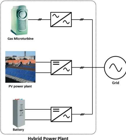
This work deals with the development of an economic supervisory predictive control method for the management of a hybrid renewable energy system. The hybrid cell integrates solar panels, a gas microturbine and a storage unit. Tuning the predictive controller is easy: the optimal criterion encom-passes the environmental, fuel, energy delivery and storage costs. Short time predictions of the solar power are embedded in the supervisor which yields smoother battery control and better power management. Real-time experiments are driven in a Hardware-in-the-Loop framework illustrating the relevance of the proposed supervisory predictive control design.
Keywords: Economic model predictive control, power system control, supervisory predictive control, renewable hybrid system, hardware in the loop.
1. Introduction
Renewable and alternative energy technologies are receiving worldwide attention. However, their integration in the power grid remains a challeng-ing task. Because of changchalleng-ing weather (e.g. solar radiation or wind speed variations), the power of renewable sources is intermittent. One way to deal
with the variable output of these energy generation systems is through the use of hybrid cells. Hybrid cells integrate renewable power sources, storage units and conventional sources in order to deliver a reference power to the grid [1–3]. This paper focuses on the supervision and optimal management of a hybrid power cell, which requires to consider the variety of dynamics and the versatility of the power sources. The supervisor generates the power references fed to the cell components.
In the literature, many heuristic methods have been proposed for the su-pervision of a hybrid cell. They use a set of rules to decide the amount of control to be applied at each time [4–8]. For example, in [5], a fuzzy su-pervisor selects the mode of power supply and controls the load share of a distributed wind-storage power system according to the actual wind power. These methods can work model-free, but are sub-optimal. Moreover, their implementation and tuning become more complex as the number of variables increases. Global optimization algorithms have allowed to consider economic objectives. However, the intermittent sources are only seen as disturbances or uncertain negative loads and power predictions are not harnessed [9, 10]. Predictive supervision strategies seem to be more suitable for hybrid cell supervision. Predictive control handles a cost function and is able to encom-pass predictable disturbances. Thanks to the receding horizon strategy, a predictive controller can take scheduled reference power changes or renew-able power forecast into account. Model predictive control (MPC)has thus been used in several hybrid power plant control strategies (e.g. [11, 12]). There are few real-time supervisors of power systems based on economic objectives explicitly. A supervisory predictive controller with an economic criterion for the optimal management of standalone wind-solar energy gener-ation has been proposed in [13–15]. However, the controller did not exactly use an Economic Predictive algorithm. Indeed, artificial weights were in-troduced in the quadratic criterion in order to smooth the battery State Of Charge (SOC). In [16], a simple linear economic criterion was introduced for power flow management. The non-convex Economic MPC control of a re-frigeration unit, which included energetic considerations, was proposed in [7]. This paper fills in a gap and proposes a true economic predictive super-visor for a hybrid power cell. Contrary to existing predictive supersuper-visors, the economic criterion is only based on actual costs and is a nonstandard function - i.e. not as for a standard Linear Quadratic regulator - of the
control variables. Moreover, the supervisor embeds explicitly the renewable power predictions. The objective of the present work is to develop an Eco-nomic Supervisory Predictive controller (ESP) for the optimal operation and management of a hybrid cell. This cell comprises a microturbine, a storage unit and solar panels. The ESP will compute the reference powers accord-ing to financial considerations, encompassaccord-ing renewable energy tariffs as well as storage, fuel and environmental costs. At first, a closed-loop model of each component of the hybrid cell will be presented. Next, the design of the objective function will be addressed and the predictive control problem will be solved. Eventually, real-time experiments in a Hardware In the Loop (HIL) framework, i.e. mixing real and emulated components, will show the relevance of the economic supervisory predictive approach.
2. HYBRID CELL ARCHITECTURE AND COMPONENT CON-TROL
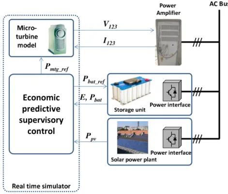
The different components of the hybrid cell (an emulated microturbine, real solar panels and a real storage unit) are connected to the grid via elec-tronic converters (Fig. 1). Since the microturbine and solar panels are fixed, the sizing of the storage unit and the power planning are subsequently de-signed using the software HOMER. The optimization is done on the basis of a one year range. The time-scale of the hybrid cell supervision is much shorter, as the prediction horizon value is only 10 s. In the framework of the design and the validation of the predictive supervisory controller, three kinds of models need to be considered:
• a general (closed-loop) model for simulation purposes,
• a simplified model, if possible linear, in order to design the supervisor, • real-time devices or emulated models which are used for validation. The predictive supervisor will, in this case, deliver the power references to the storage unit and the microturbine. The dynamical models, which are described thereafter, will be embedded into the optimization problem.
0 200 400 600 800 1000 1200 1400 −0.1 0 0.1 0.2 0.3 0.4 0.5 0.6 Time(s) Solar Power kW Predicted power Real Power
Figure 2: Measured and predicted photovoltaic power
2.1. Solar power prediction
The photovoltaic system consists of 108 modules BP solar 3160; each delivers a power of 160W. These modules are connected to a 3-phase grid via an inverter. As will be shown later, the predictive supervisor can take advantage of solar power short-term predictions. Numerous solar power fore-casting methods have been proposed so far, such as physical and statistical approaches, parametric models and trend curves, etc. [17]. Out of several trend functions (linear, quadratic, exponential), the linear trend gives the best results. Only the comparison between the estimated and the measured values is shown ( Fig. 2). The solar power is measured during a cloudy day. The prediction horizon Hp is equal to 10 s. This predictor is simple and accurate and thus fits for real-time implementation. As will be seen later, a solar power profile can be reused (stored and then emulated) in the HIL framework to compare several algorithms.
2.2. Storage unit
The storage unit combined with the microturbine is used as a backup for the solar array. The model describing the relationship between the voltage, current and the SOC of a battery can be found in [18]. A simplified model is used to represent the battery storage:
Pbat= 1 τps + 1 ˆ Pbatref, (1) ˆ
Pbatref = max(min(Pbatref, Pmax), Pmin), (2) where s is the Laplace operator, Pbatref, Pbatare the storage unit reference and real output powers; ˆPbatref is the saturated reference power and Pmax, Pmin are respectively the maximum power of charge and the maximum power of discharge.
It is assumed that the storage unit SOC is a function of the integral of the power (in the working range). In the case of SOC saturation, if !0tPbatdt > Emax or
!t
0 Pbatdt < Emin , then Pbat = 0. Emax and Emin are respectively the maximum and minimum stored energy. τp = 5s is the time constant of the battery.
When there is no saturation, one has a first-order equation: Pbat=
1 τps + 1
Pbatref. (3)
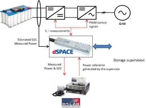
This model is implemented on a dedicated test bench which comprises a set of supercapacitors. Fig. 3 shows the principle of this storage unit, for which the power reference can be generated through a power amplifier. The supercapacitors are connected to the grid via two converters, an interlaced chopper (reduces current ripple) and an inverter. The supercapacitors consist of 6 Maxwell modules in series, the characteristics of each being 48V, 160F. In this case, the models used for design and validation are identical. The charge and discharge of the storage unit is fast, which is a limitation with respect to a lead-acid battery but will enlighten the relevance of the SOC management.
2.3. Microturbine generator
Microturbine generators are known to deliver clean energy from a wide range of fuels with a low level of gas emissions. As traditional gas turbines,
Figure 3: Storage unit test bench
they have a gas compressor, a gas turbine and a recuperator, along with a high speed permanent magnet synchronous generator, power electronic devices and their grid interface. In this paper, a simplified model is taken into account without recuperator (considered as a simple heat exchanger). Also, complexities with start-up and shut-down operations are discarded.
Generally, the control structure of a MTG includes three important con-trol blocks monitoring respectively speed, acceleration and temperature [19, 20]. The main control unit consists of the speed controller. The acceleration controller is mainly used to limit the rate of rotor acceleration at start-up. The temperature controller restricts the temperature at a predetermined fir-ing temperature. The simplified model only retains the speed loop, as shown in Fig. 4. One has:
Cm = 1.3(Wf − 0.23) + 0.5(1 − N), (4)
N = 1
Tls + 1
Figure 4: Main block of microturbine model adapted from [19] Wf = 1 Tfs + 1 a cs + b(0.77N.V CE + 0.23), (6) The speed controller is:
V CE = 25
0.05s + 1(Nref − N), (7)
where Cm, N, Wf are the per unit rotor torque, rotor speed, fuel flowrate, V CE is the per unit fuel command per unit speed, the turbine power Pmtg is the product of speed and torque. Tl, Tf, a, b, c are respectively the turbine rotor time constant, fuel system time constant, and fuel system transfer function parameters. This model is implemented into the real-time simulator for validation. In the case of ”stiff” turbines, it is possible to simplify the closed-loop model of the microturbine, which finally reduces to a fourth-order transfer function:
Pmtg =
1
(T1s + 1)(T2s + 1)(T3s2+ T4s + 1)
Pmtgref, (8)
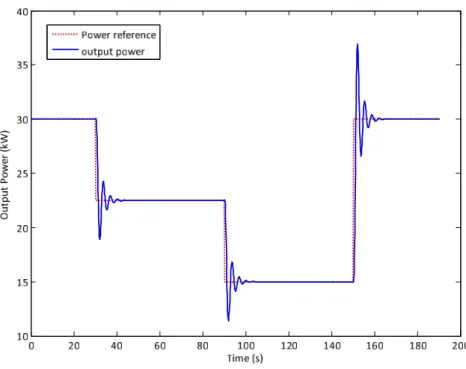
where T1 = 0.05, T2 = 0.15, T3 = 0.22 and T4 = 0.27. This coarse linear model shows a good agreement with the full model in the region where the microturbine operates when embedded in the hybrid cell. This model is used in the Model Predictive controller design procedure. One can see in Fig. 5
Figure 5: Actual and reference powers
that the electrical power produced by the microturbine follows the required reference; simulations are consistent with that found in the example by [21]. Finally, the simplified dynamical model of the cell along with the storage unit and the microturbine can be put under the discrete-time state-space form:
xk+1 = Axk+ Buk, yk = Cxk (9) where the subscript k indicates the kth sample , x is the state space, the vector of controllable powers, y = (PbatPmtg)T is the output, and the vector of power references u = (PbatrefPmtgref)T is the input vector that will be computed by the supervisor.
3. DESIGN OF AN ECONOMIC PREDICTIVE SUPERVISOR 3.1. Design of an economic criterion
Model Predictive Control (MPC) is a finite horizon optimization algo-rithm applied to a discrete-time model of a dynamical system. A controller which minimizes a cost function depending on the state and input of the
Figure 6: Simplified control scheme
process is computed over a time window [t, t + Hp]. The possible state tra-jectories that can be obtained from the current state are explored using a prediction based on the dynamical model. Via Euler-Lagrange equations, a sequence of optimal controls can be found which minimizes the optimization cost function over the prediction horizon. Typically, in our case, the criterion is a quadratic function of the future controls, the use of Sequential Quadratic Programming (SQP) optimization packages is used which provides, at every instant, the sequence of relevant control values. The first step of the con-trol strategy is implemented, the calculations are carried out from the new value of the discrete-time state. Hence, the MPC is called a receding horizon strategy as the horizon is shifted forward. Hence, the main objective of the ESP controller is to manage the power flow of the hybrid cell by minimizing the actual operational cost over a short-term receding horizon. The costs considered are the price for gas consumption Cf uel, the tax imposed by the government on carbon dioxide emissions Cemissions, the battery cycling cost Ccycling, and a cost that accounts for tariff policies. The controller determines the power reference of the microturbine Pmtgref and the power reference of the storage system Pbatrefat each time-step over a finite horizon. One has to solve an optimization problem that minimizes the cost function subjected to model and operational constraints. The microturbine operates in closed-loop with the local speed controller described previously.
The prediction horizon Hpis chosen by a tradeoff between solar prediction accuracy (which decreases with the prediction horizon length) and the other
components’ time constants. In this work, the prediction and control (that is, optimization) horizons are the same. Fig. 6 shows the simplified control scheme. The total power delivered by the cell Pt is :
Pt= Ppv+ Pbat+ Pmtg. (10)
The discretized performance index at control step k over a prediction horizon Hp is as follows: J = "Hp k=0α(Pd,k− Ppv,k − Pbat,k− Pmtg,k)2+ "Hp k=0Cf uel,k+ "Hp k=0Cemissions,k+ "Hp k=0Ccycling,k (11)
where the subscript k corresponds to the value of a variable at sample k. The financial cost J can be expressed in e. The weight α ((e/W2) is not artificial but corresponds to a tariff policy defined by the grid manager which penalizes the gap between the required power Pd,k and the delivered power Pt,k = Ppv,k + Pbat,k + Pmtg,k. Pbat,k, Pmtg,k correspond respectively to the storage unit and microturbine powers to be determined by the algorithm. Ppv,k corresponds to the solar power predictions over the receding horizon. The reference power delivered by the storage unit and the microturbine will be equal to Pd,k− Ppv,k. Hence, the accuracy of the predictions is quite im-portant. More complications can be added in the same principle of ESP, e.g. penalty criterion from the grid manager. The individual contributions are given thereafter.
A- Fuel cost model
Since little is known about the operating cost of a real microturbine, it is chosen to use the cost function of a diesel generator, Cf uel. This cost is expressed as a non-linear function of the produced power Pmtg [22] and is shown in the following equation:
Cf uel = CF[BPN mtg+ APmtg], (12) where :
• CF is the fuel price (e/l),
• PN mtg is the rated power (kW),
• Pmtg is the generator output power(kW), • Cf uel is the fuel consumption cost (e).
The cost is thus an affine function of the microturbine power. B- Pollutant emissions (CO2)
CO2 emission E is directly related to the fuel consumption, which can be approximated by a quadratic function of the generator power Pmtg as [23] :
E(Pmtg) = A + BPmtg+ CPmtg2 (13) where A, B, C are scalar coefficients. As an example, France issued a carbon tax (17 e/ton) with a new levy on oil, gas and coal consumption:
Cemisions = 0.017∗ E(Pmtg). (14) C- Battery cycling cost
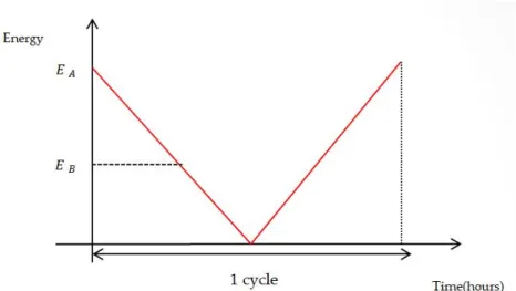
Battery cycle lifespans vary according to their type and monitoring policy. The value of a mean cycle (full charge and full discharge as shown in Fig. 7) is given by the total cost of the storage unit divided by the lifespan (in cycles):
cycle cost = cost of the battery
number of expected cycles (15)
Since the battery usually does not finish a complete cycle, the cost of a portion of cycle is given by:
portion of a cycle cost = 1 2 # EB− EA EA $ (cycle cost) (16) The factor 1/2 accounts for the charge and discharge of the battery during a full cyle (see Fig. 7 ). Assuming that the SOC varies linearly, the cycling cost can be defined as:
Ccycling = λ % % % %dSOCdt % % % %, (17)
Figure 7: Full discharge and full charge of a battery
where λ can be calculated from equation ( 16).
Traditional predictive controllers often use explicit quadratic criteria which involve the square of the control input and the square of the output error. The criterion presented in this paper has also linear and quadratic terms, but these are obtained in a quite different way, only on an economic basis. 3.2. Working out the predictive controller
As is said before, the predictive control strategy computes the storage unit and the microturbine power references by minimizing the economic criterion J. Additional operational constraints which limit the reference power change rate [13] need to be considered. The microturbine must work at a load level more than 50% of its nominal power, let otherwise the efficiency will decrease drastically:
15kW ≤ Pmtgref ≤ 30kW. (18)
Inner-loop constraints on the fuel flowrate Fmtg read:
0≤ Fmtg≤ Fmax. (19)
The battery operational constraints include power and capacity limita-tions: improper depletion or battery overcharge should be avoided. The
battery SOC is kept within reasonable limits to increase life duration of the battery: −5kW ≤ Pbatref≤ 5kW. (20) 0.5≤ SOC ≤ 0.8. (21) and dSOC dt ≤ 0.1. (22)
Instead of imposing a maximum rate of variation for the reference or real powers, it has been chosen to restrain the variation of the SOC. It is not mandatory to restrain formally the variation of the microturbine power which is already limited by a comparatively slow dynamics. Eventually, it is not possible to enforce the rate of variation of the total power which embeds the possibly fast variations of the solar power. The overall predictive control problem can be put under the following form, at each sample time:
minimize Pbatref,k,Pmtgref,k J subject to ( 18)( 20)( 21)( 22)( 19),∀k ≤ Hp. xk+1 = Axk+ Buk, yk= Cxk (23)
As was shown in the previous subsection, the criterion depends explicitly, in a Linear Quadratic form, on the storage unit and microturbine powers Pbat,kand Pmtg,k. The computation of a solution to the QP problem is handled using a standard optimization routine. A sequence of reference trajectories is found, only the first value is used by the ESP, and the procedure is repeated at each sample time.
4. HARDWARE IN THE LOOP VALIDATION 4.1. Power Hardware In the Loop Structure
The Power HIL principle is applied on the RT-LAB simulator. This simulator can run real time models on a multi-CPU computer and emulate some physical components of the hybrid renewable power plant (for more details about implementation, see [21]). The architecture used in this paper is illustrated in Fig. 8. The power amplifier interconnects the simulated components to the real ones. Hence, it is possible to create a real power from a (simulated) component model through the real-time simulator. The same is done for the microturbine represented previously in Fig. 4. This
Figure 8: Power Hardware In the Loop architecture
simulated source is blended with the real power measurements of the solar panels and of the real storage unit in order to deliver the required total cell power. Standard solar power profiles are used to make a fair comparison of algorithms. Power measurements from solar panels are collected for the first time and then emulated with the real time simulator, ensuring repeatable external conditions. In our case, the ESP is designed with a receding horizon Hp = 10s, references are sent every T = 1s, and the sampling time is fixed to 0.01s.
4.2. Real-time simulations
At first, some simulations are undertaken to verify the feasability of the approach. Table 1 is showing the good match between simulations and real-time results for a standard profile. The Mean Relative Absolute Prediction Error (MRAPE) for each of the simulated and real components’ powers never exceeds 10 %. The MRAPE for the total power is below 2 % .
Table 1: Mean relative absolute error ”%” Total power Turbine power Battery power
1.7 6.4 8.3
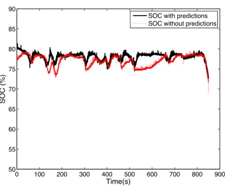
During the first real-time experiment, the reference power is kept to 30 kW and the solar power is slightly variable. In order to enlighten the rel-evance of integrating the solar predictions into the supervisor, results are compared with the same controller working without predictions. In the lat-ter case, the solar power is considered as a measured disturbance as in [13]. Results are also compared with that given by a rule-based controller for which the decision tree is given in Fig. 9 (only for off-line simulations). As expected, the predictive controllers outperform a basic rule-based controller. Results are shown in Table 2. The Mean Relative Absolute Error between the total power and the power reference when using the controller proposed in this paper is M RAE = 1.86%. The microturbine and battery powers are maintained within their respective limits. The use of predictions does not improve the total cost but allows a better management of the battery power. Indeed, the battery power profile is more smooth when predictions are used which is confirmed by the evolution of the SOC shown in Fig. 10. Fig. 11 and Fig. 12 are showing the experimental results respectively for a standard solar profile when the solar power is predicted and not predicted. When the solar power is not predicted, the storage unit compensates the fluctuations of the solar power directly. However, when solar power predictions are used, the power tracking is worse because of the discrepancy between real and pre-dicted solar powers. Since the total cost is almost the same, one will prefer to use solar power predictions in order to obtain better battery management, and leave them when better power tracking is desired.
Real-time experiments for an ESP with predictions are now proposed for a steady and an unsteady solar power profiles in order to evaluate the be-havior of the algorithm. The following figures are showing the corresponding powers and SOC. When the solar power is steady, the variations of the micro-turbine and battery powers are small, , according to the results in Fig. 13. The drift in the SOC of the storage unit can reach 5% as seen in Fig. Fig. 14. The tracking of the total power reference is nearly perfect, and, with respect to a one-step-ahead algorithm, the results will be little improved. On the contrary, the predictive approach is more interesting when the solar power
Figure 9: Flowchart of a rule-based controller 0 100 200 300 400 500 600 700 800 900 50 55 60 65 70 75 80 85 90 Time(s) SOC (%)
SOC with predictions SOC without predictions
0 100 200 300 400 500 600 700 800 900 −10 0 10 20 30 40 50 60 Time(seconds) Power (kW) Total power Microturbine power Battery power Solar power Power reference
Figure 11: Power of each element of the microgrid while taking into account the solar predictions
0 100 200 300 400 500 600 700 800 900 −10 0 10 20 30 40 50 60 Time(seconds) Power (kW) Total power Microturbine power Battery power Solar power Power reference
Figure 12: Power of each element of the microgrid without taking into account the solar predictions
Table 2: Cost function components
hierarchical ESP without ESP with algorithm predictions predictions Emission CO2 (Kg) 358 385.58 371.82 Emission cost (e) 6.1 6.55 6.32 Fuel cost (e) 55.33 30.14 31.45 Battery cycling cost (e) 1.78 5.83 4.76 Total cost (e) 63 42.52 42.53
varies more significantly. One can see from Fig. 16 that the storage unit is quickly used and then hands over to the microturbine, which dynamics is much slower. The microturbine will in turn allow the battery to recharge while keeping the total power close to its reference value (see 15). This behavior is not really intuitive; tracking is not very good when the solar power varies quickly due to the components’ inertia and solar power predic-tion errors . Moreover, it could be interesting to see if better tracking and smoothing of the power profiles could be achieved. Instead of enforcing hard constraints on the power rates of variation, an alternative would consist of detecting abrupt changes, then decrease the value of the receding horizon. This will give a more reactive control during a short time. On the contrary, increase the receding horizon for steady operating conditions.
5. Conclusion
The economic supervisory predictive control of a hybrid renewable energy system is designed according to technical and financial considerations. The supervisor sends the reference power to every controllable component of the cell. The design of a nonstandard quadratic and economic criterion and the use of dynamical models allow rapid and effective tuning of the supervisor. The predictive strategy allows to take short-time renewable power
predic-0 100 200 300 400 500 600 700 800 900 −10 0 10 20 30 40 50 60 Time(seconds) Power (kW) Total power Microturbine power Battery power Solar power Power reference
0 100 200 300 400 500 600 700 800 900 50 55 60 65 70 75 80 85 90 Time(s) SOC (%)
0 100 200 300 400 500 −10 0 10 20 30 40 50 60 Time(seconds) Power (kW) Total power Microturbine power Battery power Solar power Power reference
0 100 200 300 400 500 50 55 60 65 70 75 80 85 90 Time(s) SOC (%)
tions, SOC limitations and the battery cycling cost into account which yields better battery management. An experimental testbed is developed which combines real and simulated devices, in a Hardware in the Loop framework. Hence, this supervision strategy can be implemented in real-time and with true components. The experimental results are close to that expected from off-line simulations and show the relevance of the theoretical developments. Several solar power profiles have been tested, showing that results are quite good when the solar power varies in reasonable ranges. When variations are much faster, the tracking is not so good, because of the possible discrepan-cies between the real and predicted solar powers. It can be expected that an adaptive algorithm where the prediction horizon is a function of the so-lar power prediction accuracy, that is, the horizon is shrunk when fast soso-lar power variations occur, would improve the existing results. Such an adaptive approach is the topic of future research. Another perspective is to generalize the methodology to large-scale units, by incorporating new elements.
[1] S. Leva, D. Zaninelli, Hybrid renewable energy-fuel cell system: Design and performance evaluation, Electric Power Systems Research 79 (2009) 316–324.
[2] M. Nehrir, C. Wang, K. Strunz, H. Aki, R.Ramakumar, J.Bing, Z. Miao, Z.Salameh, A review of hybrid renewable/alternative energy systems for electric power generation: Configurations, control, and applications, IEEE Transactions on Sustainable Energy 2 (2011) 392–403.
[3] G. Venkataramanan, M. Stadler, A. Siddiqui, R. Firestone, B. Chan-dran, C. Marnay, Optimal technology selection and operation of commercial-building microgrids, IEEE Transactions on Power Systems 23 (2008) 1–10.
[4] G. Boukettaya, L. Krichen, A. Ouali, Fuzzy logic supervisor for power control of an isolated hybrid energy production unit, Journal of Electri-cal and Power Engineering 29 (2007) 279–285.
[5] V. Courtecuisse, J. Sprooten, B. Robyns, M. Petit, B. Francois, J. Deuse, A methodology to design a fuzzy logic based supervision of hybrid re-newable energy systems, Mathematics and Computers in Simulation 81 (2010) 208–224.
[6] A. Hajizadeh, M. Golkar, Intelligent power management strategy of hybrid distributed generation system, International Journal of Electrical Power and Energy Systems 29 (2007) 1264–1280.
[7] T. G. Hovgaard, L. F. S. Larsen, M. J. Skovrup, J. B. Jorgensen, Opti-mal energy consumption in refrigeration, systems - modelling and non-convex optimisation, The Canadian Journal of Chemical Engineering 90 (2012) 1426–1433.
[8] A. Mohamed, O. Mohammed, Real-time energy management scheme for hybrid renewable energy systems in smart grid applications, Electric Power Systems Research 96 (2013) 133–143.
[9] D. Ipsakis, S. Voutetakis, P. Seferlis, F. Stergiopoulos, C. Elmasides, Power management strategies for a stand-alone power system using re-newable energy sources and hydrogen storage, International Journal of Hydrogen Energy 34 (2009) 7081–7095.
[10] F. Mohamed, H. Koivo, System modelling and online optimal man-agement of microgrid using mesh adaptive direct search, International Journal of Electrical Power and Energy Systems 32 (2010) 398–407. [11] F. Guerin, D. Lefebvre, V. Loisel, Supervisory control design for systems
of multiple sources of energy, Control Engineering Practice 20 (2012) 1310–1324.
[12] F. Valenciaga, P. Puleston, Supervisory control for a stand-alone hybrid generation system using wind and photovoltaic energy, IEEE Transac-tions on Energy Conversion 20 (2005) 398–405.
[13] J. Liu, X. Chen, P. Christofides, W. Qi, Supervisory predictive control of standalone wind/solar energy generation systems, IEEE Transactions on Control Systems Technology 19 (2011) 199–207.
[14] J. Liu, X. Chen, P. Christofides, W. Qi, A distributed control framework for smart grid development: Energy/water system optimal operation and electric grid integration, Journal of Process Control 21 (2011) 1054– 1516.
[15] W. Qi, J. Liu, P. D. Christofides, Distributed supervisory predictive control of distributed wind and solar energy systems, IEEE Transactions On Control Systems Technology 21 (2013) 504–513.
[16] T. G. Hovgaard, K. Edlund, J. B. Jorgensen, The potential of economic mpc for power management, 49th IEEE Conference on Decision and Control (2010).
[17] C. Paolia, C. Voyanta, M. Musellia, M. Niveta, Forecasting of prepro-cessed daily solar radiation time series using neural networks, Solar Energy 84 (2010) 2146–2160.
[18] S. Chungpaibulpatana, W. Ongsakul, Y. Sukamongkol, A simulation model for predicting the performance of a solar photovoltaic system with alternating current loads, Renewable Energy 27 (2002) 237–258. [19] F. Pai, S. Hung, A design and operation of power converter for
microtur-bine powered distributed generator with capacity expansion capability, IEEE Transactions on Energy Conversion 23 (2008) 110–118.
[20] Y. Zhu, K. Tomsovic, Development of models for analyzing the load-following performance of microturbines and fuel cells, Electric Power Systems Research 62 (2002) 1–11.
[21] J. Martinez, V. Dinavahi, M. Nehrir, X. Guillaud, Tools for analysis and design of distributed resourcespart iv: Future trends, IEEE Transactions on Power Delivery 26 (2011) 1671–1680.
[22] R. Dufo-Lopez, J. Bernal-Agustin, Design and control strategies of pv-diesel systems using genetic algorithms, Solar Energy 79 (2005) 33–46. [23] S. Johansen, O. Hansen, T. Gjengedal, A qualitative approach to

![Figure 4: Main block of microturbine model adapted from [19]](https://thumb-eu.123doks.com/thumbv2/123doknet/7425087.219375/9.892.225.690.191.434/figure-main-block-microturbine-model-adapted.webp)