ECOLE DE TECHNOLOGIE SUPÉRIEURE UNIVERSITÉ DU QUÉBEC
MANUSCRIPT-BASED THESIS PRESENTED TO ÉCOLE DE TECHNOLOGIE SUPÉRIEURE
IN PARTIAL FULFILLMENT OF THE REQUIREMENTS FOR THE DEGREE OF DOCTOR OF PHILOSOPHY
Ph.D.
BY
Yamina BOUGHARI
FLIGHT CONTROL OPTIMIZATION FROM DESIGN TO ASSESSMENT APPLICATION ON THE CESSNA CITATION X BUSINESS AIRCRAFT
MONTREAL, 24TH OF JANUARY 2017 © Copyright 2017 All rights reserved by Yamina Boughari,
© Copyright
Reproduction, saving or sharing of the content of this document, in whole or in part, is prohibited. A reader who wishes to print this document or save it on any medium must first obtain the author’s permission.
BOARD OF EXAMINERS
THIS THESIS HAS BEEN EVALUATED BY THE FOLLOWING BOARD OF EXAMINERS
Mrs. Ruxandra Mahela Botez, Thesis Supervisor
Department of Automated Production Engineering at École de technologie supérieure
Mr. Thien-My Dao, President of the jury
Department of Mechanical Engineering at École de technologie supérieure
Mr. Guy Gauthier, Member of the jury
Department of Automated Production Engineering at École de technologie supérieure
Mr. Hekmat Alighanbari, External Evaluator
Department of Aerospace Engineering at Ryerson University
THIS THESIS WAS PRENSENTED AND DEFENDED
IN THE PRESENCE OF A BOARD OF EXAMINERS AND THE PUBLIC 1ST DECEMBER, 2016
ACKNOWLEDGMENTS
First and foremost, I would like to express my sincere gratitude to my supervisor, Prof. Ruxandra Mihaela Botez for her support throughout the duration of my research project, for her constant encouragement, for the motivation to participate at conferences and networking events, and for presenting me the great opportunity of teaching, without her continuous guidance and persistent help this dissertation would not have been possible.
Thanks to the project leader Mr Ken Dustin and his team at CAE Inc. for their support in the development of the Aircraft Research Flight Simulator at the LARCASE laboratory. Thanks are also due to Mrs Odette Lacasse and Mr Oscar Carranza at ETS for their continuing enthusiasm and support.
I am very much thankful to all past and present members of LARCASE who participated and contributed to the realization of this project, especially Georges and Florian for their suggestions, dedication and hard work, for Alejandro Murrieta, for reading some of my papers and given me valuable advices.
A great thank you to my family in Algeria, my friends, for their love, encouragement and support, to my husband Youssef, my son Mohammed Amine, for their patience, also to my step family, and special thank to Carol who took care of my child during my absences.
I owe my deepest gratitude to my mother, Auda, my father Abd El Kader and my brother Moustapha, for their continuous support, without them I would not be where I am, nor would I be the person that I am today. I also dedicate this dissertation to the memory of my uncle Mohammed.
Above all, thanks to the Great Almighty, author of knowledge and wisdom for his countless love.
FLIGHT CONTROL OPTIMIZATION FROM DESIGN TO ASSESSMENT APPLICATION ON THE CESSNA CITATION X BUSINESS AIRCRAFT
Yamina BOUGHARI ABSTRACT
New methodologies have been developed to optimize the integration, testing and certification of flight control systems, an expensive process in the aerospace industry. This thesis investigates the stability of the Cessna Citation X aircraft without control, and then optimizes two different flight controllers from design to validation. The aircraft’s model was obtained from the data provided by the Research Aircraft Flight Simulator (RAFS) of the Cessna Citation business aircraft.
To increase the stability and control of aircraft systems, optimizations of two different flight control designs were performed: 1) the Linear Quadratic Regulation and the Proportional Integral controllers were optimized using the Differential Evolution algorithm and the level 1 handling qualities as the objective function. The results were validated for the linear and nonlinear aircraft models, and some of the clearance criteria were investigated; and 2) the
H-infinity control method was applied on the stability and control augmentation systems. To
minimize the time required for flight control design and its validation, an optimization of the controllers design was performed using the Differential Evolution (DE), and the Genetic algorithms (GA). The DE algorithm proved to be more efficient than the GA. New tools for visualization of the linear validation process were also developed to reduce the time required for the flight controller assessment.
Matlab® software was used to validate the different optimization algorithms’ results. Research platforms of the aircraft’s linear and nonlinear models were developed, and compared with the results of flight tests performed on the Research Aircraft Flight Simulator. Some of the clearance criteria of the optimized H-infinity flight controller were evaluated, including its linear stability, eigenvalues, and handling qualities criteria. Nonlinear simulations of the maneuvers criteria were also investigated during this research to assess the Cessna Citation X’s flight controller clearance, and therefore, for its anticipated certification.
Keywords: Linear Fractional Representation, Flight Control Certification, Stability Analysis,
OPTIMISATION DE LA COMMANDE DE VOL DE LA CONCEPTION A L’ÉVALUATION APPLICATION A L’AVION D’AFFAIRE CESSNA CITATION X
Yamina BOUGHARI RÉSUMÉ
Afin d’améliorer le processus coûteux d’intégration, d’essai et de certification des systèmes de commande de vol des avions civils dans l'industrie de l'aérospatiale, de nouvelles méthodologies ont été développées pour son optimisation. Le modèle de l'avion a été obtenu à partir des données fournies par le simulateur de vol de recherche de l’avion. Dans cette thèse, on a étudié la stabilité du Cessna Citation X sans contrôle, puis deux contrôleurs différents de vol ont été optimisés a partir de leur conception jusqu’ à leur validation sur l'avion Cessna Citation X.
Pour augmenter le système de stabilité et de contrôle de l'aéronef, des optimisations de deux conceptions différentes d’un contrôleur de vol ont été effectuées; d'une part, la méthode moderne de la régulation quadratique linéaire et la méthode classique de la commande proportionnelle intégrale ont été optimisées en utilisant l'algorithme de l’évolution différentielle, et en utilisant le niveau 1 des qualités de manœuvrabilités comme fonction objective. Les résultats on été validés pour les modèles linéaire et non linéaire de l’avion, et quelques critères de certification ont été évalués.
D'autre part, au lieu d'utiliser une combinaison de deux méthodes de contrôle ci haut mentionnées, la méthode de contrôle H-infini a été utilisée pour assurer l’obtention des systèmes d'augmentation de la stabilité et de contrôle. Pour réduire le temps entre la conception de la commande de vol et la validation, une optimisation de la conception de contrôleur a été réalisée en utilisant l'algorithme de l’évolution différentielle, et l’algorithme génétique. L'algorithme de l’évolution différentielle a montré plus d'efficacité que l’algorithme génétique; également de nouveaux outils pour la visualisation du processus de validation linéaire ont été développés pour réduire le temps requis pour l’évaluation du contrôleur de vol.
Pour valider les différents résultats obtenus par des optimisations des algorithmes, le logiciel Matlab a été utilisé dans lequel des plateformes de recherches du modèle linéaire et non linéaire de l'aéronef ont été développés et ont été comparées à des essais en vol effectués sur le simulateur de vol de recherche de l’avion.
Quelques critères de certification du contrôleur de vol conçu avec H-infini optimisé tel que la stabilité linéaire, les valeurs propres, et les critères de qualités de manœuvrabilités ont été évalués ; en outre, des critères de simulation de manœuvres des modèles non linéaires ont été étudiés au cours de cette recherche visant à évaluer l'avion d'affaires pour la certification future du contrôleur de vol.
X
Mots clés : Représentation fractionnaire linéaire, Certification du control de vol, Analyse de
TABLE OF CONTENTS Page INTRODUCTION ...1 0.1 Problem Statement ...1 0.2 Objectives ...4 0.3 Methodology ...6
0.3.1 Cessna Citation X business aircraft model ... 6
0.3.2 Aircraft dynamics ... 7
0.3.3 Flight envelope using LFR models design by flight point’s interpolation ………… ... 10
0.3.4 Stability analysis interface ... 14
CHAPITRE 1 LITTERATURE REVIEW ...17
1.1 Aircraft Flight Control System ...17
1.2 Flight Control Optimization ...17
1.3 Linear Quadratic Regulation (LQR) ...18
1.4 H-infinity Controller...20
1.5 Aircraft Clearance Criteria ...23
1.6 Linear Stability Criteria ...26
1.7 Cessna Citation X Clearance Criteria Evaluation ...26
CHAPITRE 2 APPROACH AND ORGANIZATION OF THE THESIS ...29
CHAPITRE 3 CESSNA CITATION X BUSINESS AIRCRAFT AEROELASTIC STABILITY FLIGHT ENVELOPE ANALYSIS USING LFR MODELS - USING A NEW GUI FOR THE EASY MANIPULATION OF LFRs...37
3.1 Introduction ...39
3.2 Cessna Citation X Business Aircraft Modeling ...43
3.3 Linear Fractional Representation (LFR) ...44
3.3.1 LFR modeling using Trends and Bands method... 50
3.3.2 Normalization ... 52
3.3.3 The Graphical User Interface GUI ... 56
3.4 Stability Analysis ...59
3.4.1 Lyapunov stability ... 60
3.4.2 Quadratic Stability ... 61
3.4.3 Resolution Method ... 62
3.4.3.1 Wang-Balakrishnan method... 64
3.4.4 Stability analysis interface ... 64
3.5 Analysis of Results ...66
3.5.1 LFR results validation ... 66
3.5.2 Stability analysis results ... 68
XII
3.6 Conclusion ...75
CHAPITRE 4 NEW METHODOLOGY FOR OPTIMAL FLIGHT CONTROL USING DIFFERENTIAL EVOLUTION- APPLICATION TO THE CESSNA CITATION X AIRCRAFT - VALIDATION ON AIRCRAFT RESEARCH FLIGHT LEVEL D SIMULATOR ...77
4.1 Introduction ...79
4.2 Problem Statement ...83
4.2.1 Aircraft control architecture using LQR and PI ... 83
4.2.2 Cessna Citation X business aircraft ... 85
4.2.3 Aircraft, actuators and sensors dynamics ... 86
4.2.3.1 Aircraft dynamics ... 86
4.2.3.2 Actuators and sensors dynamics ... 88
4.3 Flight Conditions Interpolation ...88
4.4 Design Specifications and Requirements ...92
4.5 Differential Evolution ...93 4.5.1 Initialisation phase ... 94 4.5.2 Mutation ... 95 4.5.3 Crossover ... 96 4.5.4 Selection ... 97 4.5.5 Iteration ... 97
4.6 Linear Quadratic Regulation (LQR) Method ...97
4.7 Tracking Control with PI Optimization ...98
4.8 DE Algorithm for Solving the LQR-PI Problem ...99
4.8.1 Objective function ... 100
4.9 Simulation Results Analysis ...100
4.9.1 Results validation ... 103
4.9.1.1 Linear validation ... 103
4.9.1.2 Nonlinear validation... 110
4.10 Conclusion ...112
CHAPITRE 5 FLIGHT CONTROL CLEARANCE OF CESSNA CITATION X USING EVOLUTIONARY ALGORITHMS ...115
5.1 Introduction ...117
5.2 Cessna Citation X Business Aircraft ...120
5.2.1 Aircraft dynamics ... 121
5.2.2 LFR models design by flight point’s interpolation ... 122
5.2.3 Flying quality’s level 1 ... 126
5.3 H-infinity Theory ...127
5.3.1 Definition of the standard H-infinity robust control problem ... 127
5.3.2 Definition of the mixed sensitivity H-infinity problem... 128
5.4 Differential Evolution and Genetic Algorithms ...130
5.4.1 Objective Function for DE algorithm and GA ... 130
5.4.2 Differential Evolution algorithm ... 131
XIII
5.4.2.2 Mutation ... 132
5.4.2.3 Crossover ... 132
5.4.2.4 Selection ... 133
5.4.2.5 Iteration ... 134
5.4.3 Genetic Algorithm applied to the H-infinity method ... 135
5.5 Presentation of Results ...139
5.5.1 GA and DE algorithm optimization results ... 140
5.5.2 Results for 72 flight conditions ... 142
5.5.3 Non-linear validation ... 149
5.5.4 Robustness analysis of H-infinity controller... 152
5.6 Conclusion ...153
CHAPITRE 6 OPTIMAL CONTROL NEW METHODOLOGIES VALIDATION ON THE RESEARCH AIRCRAFT FLIGHT SIMULATOR OF THE CESSNA CITATION X BUSINESS AIRCRAFT ...155
6.1 Introduction ...156
6.2 Cessna Citation X Aircraft, Actuators and Sensors Dynamic ...157
6.2.1 Aircraft dynamics ... 158
6.2.2 Actuators and sensors dynamics ... 160
6.3 Flight Controller ...161
6.4 Clearance Criteria ...161
6.4.1 Linear stability and Eigenvalue analysis ... 161
6.4.2 Linear, Nonlinear handling qualities, and Nonlinear analysis ... 162
6.4.3 Pitch control , and Rapid roll ... 162
6.5 Analysis of Results ...163
6.5.1 Stability analysis results ... 163
6.5.2 Eigenvalue results ... 164
6.5.3 Handling qualities analysis results ... 165
6.5.4 Nonlinear analysis results ... 166
6.6 Conclusion ...168
DISCUSSION OF RESULTS...169
CONCLUSION AND RECOMENDATIONS ...173
APPENDIX A ...178
LIST OF TABLES
Page
Table 0-1 Aircraft flying qualities level 1 ... ...4
Table 3-1 Normalization of Coefficients and Coordinates ...54
Table 3-2 LFR’s system order and repetitiveness ...55
Table 4-1 Actuators dynamics characteristics ...88
Table 4-2 Aircraft flying qualities and temporal criteria ...93
Table 5-1 Maximum relative error ...124
Table 5-2 Aircraft flying qualities level 1 ...127
Table 5-3 Weighting function optimization results ...143
Table 5-4 Mean γ values ...143
Table 5-5 Flight points with the worst handling qualities ...148
Table 6-1 Actuators dynamics characteristics ...160
Table 6-2 Flight points with the good handling qualities over the flight envelope ...165
LIST OF FIGURES
Page
Figure 0-1 Fly-by –wire concept ..………...……….…………1
Figure 0-2 Cessna Citation X Research Aircraft Flight Simulator (RAFS)………..…6
Figure 0-3 Representation of Cessna Citation X aircraft’s rotation axes………..7
Figure 0-4 Simulation of Linear and nonlinear model of the Cessna Citation X...….8
Figure 0-5 Cessna Citation X flight enveloppe..……….………11
Figure 0-6 Definition of 26 regions……….………...….12
Figure 0-7 Cessna Citation X Weight/ XCG conditions...………..………13
Figure 0-8 Flight points obtained by use of LFR models…..……….….13
Figure 0-9 Robust Stability Toolbox………..……….14
Figure 3-1 Representation of 1(δ1): y = K1δ1u (a) , and of K2(δ2): y = K2(δ2)u (b) ...………..46
Figure 3-2 LFR of 1 , 1 , … , ...47
Figure 3-3 The LFR of Δ bloc ...48
Figure 3-4 Cessna Citation X Aircraft Flight Envelope ...50
Figure 3-5 Cessna Citation X Weight/ XCG conditions ...51
Figure 3-6 Regions Definition ...52
Figure 3-7 Full-order LFR system versus a reduced-order LFR system ...56
Figure 3-8 (a) and (b) Graphical User Interface for generating the Cessna Citation X LFRs. ...57
Figure 3-9 Equilibrium condition ...61
Figure 3-10 Robust Stability Toolbox ...65
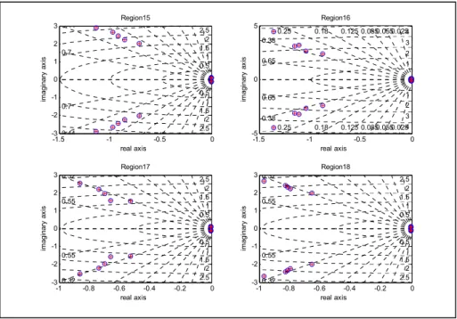
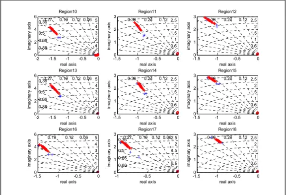
Figure 3-11 Comparison of eigenvalues for interpolated flight points with the reference values for medium altitudes (between 15,000 ft and 30,000 ft) ...67
XVIII
Figure 3-12 Comparison of eigenvalues for the interpolated flights points with the reference values at the highest altitudes
(between 35,000 ft and 40,000 ft) ...67
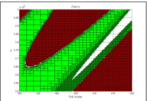
Figure 3-13 Results for the single region with 7th order discretization (altitude= 35,000ft -40,000 ft and TAS= 390 – 420 knots) ...69
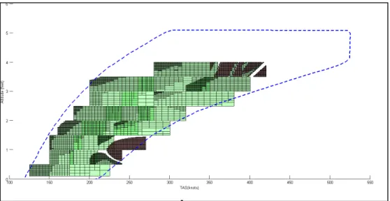
Figure 3-14 Results of a completed stability analysis ...69
Figure 3-15 Region with 5th order discretization (altitude 35000ft -40000 ft and TAS 390 – 420 knots)...71
Figure 3-16 Results of 5th order discretization of the region ...71
Figure 3-17 Stability analysis of a longitudinal model for 3rd weight/ XCG configuration (24000lbs/30%) ...74
Figure 3-18 Stability analysis of a longitudinal model for 7th weight/ XCG configuration (28000lbs/30%) ...74
Figure 4-1 Closed loop representation of the Cessna Citation X business aircraft ...84
Figure 4-2 Representation of Cessna Citation X aircraft’s rotation (body) axes ...86
Figure 4-3 Cessna Citation X Aircraft Flight Envelope ...89
Figure 4-4 Region definition ...90
Figure 4-5 Cessna Citation X Weight/ XCG conditions ...91
Figure 4-6 Flight points obtained by LFR models ...92
Figure 4-7 LQR weighting matrices and PI tuning optimization using DE algorithm ...94
Figure 4-8 GUI used in the controller design and optimization ...101
Figure 4-9 Gains scheduling with respect to the altitude and airspeed ...102
Figure 4-10 Pitch rate q (deg/sec) control and the resulting pitch angle θ (deg) ...104
Figure 4-12 Bode diagram for pitch rate q (deg/sec) control ...105
Figure 4-13 PI Tracking reference for pitch angle (deg)...105
Figure 4-14 Pole zero map for pitch angle (deg) control ...106
XIX
Figure 4-16 Tracking references for roll rate p (deg/sec) ...107
Figure 4-17 Pole zero map for roll rate p (deg/sec) ...107
Figure 4-18 Bode diagram for roll rate p (deg/sec) ...108
Figure 4-19 Roll angle φ (deg) control and the resulting roll rate p(deg/sec) ...108
Figure 4-20 Pole Zero map of roll angle φ (deg) ...109
Figure 4-21 Bode diagram of roll angle φ (deg) ...109
Figure 4-22 Pitch angle (deg) control of the nonlinear aircraft model ...110
Figure 4-23 Pitch rate q(deg/sec) control of the nonlinear aircraft model ...111
Figure 4-24 Roll angle (deg) control of the nonlinear aircraft model ...111
Figure 4-25 Roll rate p (deg/sec) control of the nonlinear aircraft model ...112
Figure 5-2 Cessna Citation X flight enveloppe ...123
Figure 5-3 Definition of 26 regions ...125
Figure 5-4 Cessna Citation X Weight/ XCG conditions ...125
Figure 5-6 Standard H_infinity configuration ...128
Figure 5-7 Mixed sensitivity H-infinity configuration ...129
Figure 5-8 Example of uniform crossover ...136
Figure 5-9 Example of crossover by section ...136
Figure 5-10 Example of mutation ...137
Figure 5-11 H-infinity optimization the Differential Evolution DE algorithm ...138
Figure 5-12 H-infinity optimization using the Real-valued Genetic Algorithm ...139
Figure 5-13 Closed loop representation of Cessna Citation X business aircraft ...140
Figure 5-14 The mean fitness versus the best fitness and the best fitness value for GA ...141
Figure 5-15 The mean fitness versus the best fitness and the best fitness value for DE ...142
XX
Figure 5-16 Responses for pitch rate presenting good handling qualities for 1st XCG position (22000 lb/33%) ...145 Figure 5-17 Response for pitch rate q presenting the worst handling qualities for the
entire envelope ...145 Figure 5-18 Flight points where the handling qualities for the pitch rate q control are
the worst ...146 Figure 5-19 Flight points coordinates ...146 Figure 5-20 Responses of the roll angle φ for the entire envelope presenting good
handling qualities ...147 Figure 5-21 Flight points where the handling qualities for
the roll angle φ control are the worst ...147 Figure 5-22 Flight points presenting the worst handling qualities
for the roll angle control φ ...148 Figure 5-23 Pitch angle rate hold control responses using
nonlinear aircraft model ...150 Figure 5-24 Altitude, true airspeed, heading and masse variation responses using
nonlinear aircraft model ...150 Figure 5-25 Roll angle φ control responses on a nonlinear aircraft model ...151 Figure 5-26 Altitude, true airspeed, heading and mass variation responses on a
nonlinear aircraft model ...151 Figure 5-27 Pitch rate q response using mass and the center variation ...152 Figure 5-28 Roll angle φ response using mass and the center variation ...153 Figure 6-1 (a) Flight envelope with LFR regions;
(b)Weight versus XCG envelope ...160 Figure 6-2 Minimum phase margin versus flight conditions per region for all Angle
of attack (up to 14 deg) ...164 Figure 6-3 Bode diagram and Nichols ...164 Figure 6-4 Aircraft stability analysis using Lyapunov function. ...165 Figure 6-5 (a) Time response for the pitch rate q and (b)
XXI
Figure 6-6 Pitch angle rate q hold control responses and the resulting altitude, true airspeed,heading and mass variation
responses of the nonlinear aircraft model ...167 Figure 6-7 Roll angle ϕ control responses of the nonlinear aircraft model ...167 Figure 6-8 Pitch rate q (a) and Roll (b) response using mass and XCG variation ...168
LIST OF ABREVIATIONS
ADMIRE Air Data Model In Research Environement CAS Control Augmentation System
COFCLUO Clearance Of Flight Control Laws Using Optimization
DE Differential Evolution
EASA European Aviation Safety Agency ESS Steady State Error
FAA Federal Aviation Administration
FBW Flight By Wire
FCL Flight Control Law FCS Flight Control System
GA Genetic Algorithm
GRATEUR Aeronautical Research and Technology GUI Graphical User Interface
HIRM High Incidence Research Model
HWEM High performance short take off and vertical landing aircraft Model LARCASE Laboratory of avionics
LFR Linear Fractional Representation LFT Linear Fractional Transformation LQG Linear Qudratic Gaussian
LQR Linear Quadratic Regulation MIMO Multi Inputs Multi Outputs
XXIV
PID Proportional Integral Derivative PIO Pilot Induced Oscilation
PSO Swarm Partical Optimization SISO Single Input Single Output
LIST OF SYMBOLS AND UNITS OF MEASUREMENTS
A,B,C,D State space matrices
p, q, r Angular speeds along Ox, Oy, Oz axis
u, v, w Speeds along the Ox, Oy, Oz axis
u(t) Control vector
x(t) State space vector
V Total Aircraft Speed
X, Z, Y Aircraft aerodynamic forces
OS Overshoot
Ts Settling Time
( , ) Lower linear fractional transformation
K Feedback Gain
Sensitivity weighting function
Complementary sensitivity weighting function
, , Elevator, aileron, and rudder deflections
θ , β, ϕ Pitch angle, sideslip angle, and roll angle
ωn Natural frequency ζ Damping coefficient γ Robustness criterion ki Integral Gain kp Kw Kq Proportional Gain Vertical speed Gain Pitch rate Gain
XXVI
P J
Q R
Positive Semi-Definite Matrix LQR Cost Function
Weighting Matrix for the states Weighting Matrix for control input
∆ Block uncertainties
V(x) System energy
Real matrices m x n Complex matrices m x n Integer number field
T A Transposition of matrix A 1 A− Inverse of matrix A * A Trans-conjugate of matrix A
INTRODUCTION
0.1 Problem Statement
The certification of an aircraft is an important and essential step in the process leading to its first flight. To prove that an aircraft is ready to fly, it must meet several criteria required by various agencies such as Transport Canada, the Federal Aviation Administration (FAA), or the European Aviation Safety Agency (EASA).
The Flight Control System (FCS) requires one of the most stringent certification processes in the aeronautical industry. The FCS is an automatic system that allows the pilot to control an aircraft during its mission, and provides for safe and economical operations. The FCS contains mechanical linkages that connect the pilot’s control inputs to the aircraft control surfaces.
Flight automation has led to the development of the Fly By Wire FCS, illustrated in Figure 0-1, which replaces the mechanical linkages by electrical signals between the pilot’s inputs and the control surfaces (aircraft actuators).
Figure 0-1 Fly-by –wire concept Taken from (DUMOLLARD, 2014)
Civil aircraft FCS clearance is a fastidious task, especially for modern aircraft that must achieve high performance standards (C. Fielding, 2002; Nelson, 1998). Flight Control Laws (FCL), defined as the relationship between a pilot’s stick input and the aircraft’s response,
2
were developed as an important part of the FCS design. FCL clearance is considered as the last step in the certification process; with FCL clearance, an aircraft has reached a mature phase in its design, and is ready for validation and verification by means of flight tests.
However, developing FCL from concept to certification is a very expensive process in terms of money and resources. Over the last few decades, much research has been done to develop advanced methods for aircraft design and analysis that enhance the flight control law (FCL) development process. Several analysis methods are now available to address virtually any realistic design challenge and to the FCL design process. FCL design can be realized in five steps, as follows (Fielding et al., 2002):
1. The FCL architecture is defined, and the desired closed-loop specifications and the handling qualities are achieved by tuning the control law parameters. Linear analysis and nonlinear simulations are performed to assess a new FCL design’s effect on an aircraft’s stability and performance.
2. To assess the handling qualities of the augmented aircraft, simulations via
pilot-in-the-loop are performed.
3. To verify if the FCL matches with the FCS hardware in the loop and operates as desired, tests are performed on a Functional Integration Bench known as the Iron Bird.
4. A clearance process verifies that the FCL fulfills all the requirements for a safe flight under a range of parameter variations and failure conditions for the entire flight envelope. 5. Flight tests are performed to validate the FCS design according to the airworthiness
requirements and to assure that it meets the customer’s expectations.
Designing an optimal FCL which meets all the desired requirements is an iterative and lengthy process, one that should be automated. There are several methods that address the controller optimality, but they usually employ an ad hoc technique to meet the design requirements. Due to the iterative nature of this process, an optimization algorithm is required to manage the engineering workload. At the Laboratory of Applied Research in Active Control, Avionics, and AeroServoElasticity (LARCASE), new optimizations based on
3
heuristic and deterministic algorithms were developed and implemented in realistic aircraft models for their identification (Ghazi, Botez et Achigui, 2015), flight trajectory optimization (Murrieta-Mendoza, Botez et Patrón, 2015), (Murrieta-Mendoza et Botez, 2015a), (Patrón, Botez et Labour, 2013), and FCL design, (Boughari et al., 2014a), (Boughari et al., 2014b; Ghazi et Botez, 2014a),(Ghazi et Botez, 2015c).
An FCL has to meet the flying qualities requirements and the closed-loop performance specifications. The main flying qualities used in FCL clearance are those that verify the linear and nonlinear aircraft maneuvers, and any that are further defined for the aircraft’s longitudinal and lateral modes.
Aircraft flying qualities are provided by the “U.S Military Specification for the Flying
Qualities of Piloted Airplanes MIL-STD-1797A.” For longitudinal aircraft motion, two
modes are perceived: 1) short period and 2) phugoïd mode. Three modes are perceived for aircraft lateral motion:1) the Dutch roll mode, 2) the roll mode, and 3) the spiral mode. These modes must respect some of the desired criteria required for very good flight performance, expressed in terms of the damping and time constants, as shown in Table 0.1. Very good flight performances must be met for the cruise phase, and for flight level 1, which corresponds to very good flying qualities (Standard, 1990), (Bailey et al., 2009), (Roskam, 1985). Thus the aircraft responses have to meet the criteria given in Table 0.1 for the aircraft certification.
4
Table 0-1 Aircraft flying qualities level 1
Criterion Type Limits
Short period damping modal 0.3 ≤ ξsp ≤ 2
Phugoid damping modal 0.04 ≤ξph
Dutch roll damping modal 0.3 ≤ξdr ≤ 2
Roll time constant temporal Tr <1.4 sec
To demonstrate that an aircraft is safe to fly requires more than a verification of the handling qualities to clear the FCL, and so exhaustive stability analysis must be performed for linear and nonlinear model design over the entire flight envelope to test the robustness of the aircraft nominal model, and that of its uncertainties.
“Linear stability” aims to prove that an aircraft is stable over the whole flight envelope with sufficient phase and gain margins (gain over 6dB and phase over 45 degrees). It is evaluated for either the open-loop aircraft system by using Nichols plots, or for the closed loop by calculating the eigenvalues (negative eigenvalues) for the whole envelope. It is obvious that linear stability and flying qualities are the crucial clearance criteria which have to be fulfilled during the FCL process from design to clearance.
0.2 Objectives
The main objective in this research is the optimization of the FCL design by using some of the clearance criteria as optimization parameters, and by automating the iterative process following the development of new tools for FCL validation. This approach has been selected
5
based on its promise to reduce the amount of resources and costs required for this optimization.
To reach the main objectives, several sub-objectives have to be fulfilled:
1. Creation of a database of Cessna Citation X aircraft linear models that covers the entire flight envelope by using the interpolation of Linear Fractional Representation models (LFR). Altitudes and True Air Speeds (TAS) are given as flight point coordinates.
2. Development of new tools for generating a Cessna Citation X aircraft LFR model; very good visualization and analysis could be achieved using a new Graphical User Interface (GUI).
3. Analysis of the natural stability of the Cessna Citation X business aircraft on its entire flight envelope, for different weight and Xcg configurations. A unique database was created to assess the Cessna Citation X aircraft clearance for any FCL design.
4. Definition of the FCL architecture for two different modern control methods, and identification of the main parameters leading to their design optimization.
5. Definition of the desired flying qualities for both longitudinal and lateral aircraft dynamics.
6. Development and implementation of in-house evolutionary algorithms to reduce the global computation time of the FCL design.
7. Development of new tools for the visualization of the aircraft linear model’s validation in its flight envelope.
8. Implementation and validation of the FCL in the aircraft nonlinear model. Carrying out tests to assess the FCL robustness for Xcg and weight variation cases due to aircraft fuel burn.
9. Evaluation of the resulting optimized FCL clearance criteria for both linear and nonlinear aircraft models.
6
0.3 Methodology
In this section, the Cessna Citation X business aircraft nonlinear and linear dynamics are described within the operating flight envelope. The “Stability Analysis Toolbox” used for the aircraft stability analysis is then briefly introduced.
0.3.1 Cessna Citation X business aircraft model
The algorithms for this research were developed in Matlab®. The aircraft nonlinear model for the development and validation of the FCL was built in Matlab/Simulink based on aerodynamics data extracted from a Cessna Citation X Level D Research Aircraft Flight Simulator designed and manufactured by CAE Inc., presented in Figure 0-2. According to the Federal Administration AviFation (FAA, AC 120-40B) (FAA, 1991), Level D is the highest certification level that can be delivered by the FAA Certification Authorities for flight dynamics. More than 100 flight tests were performed on the Citation X Level D Research Aircraft Flight Simulator within its flight envelope. Due to its high certification level for its flight dynamics, the RAFS was flown as a real aircraft, and its flight test data were used for this research.
Figure 0-2 Cessna Citation X Research Aircraft Flight Simulator (RAFS)
7
Trim and linearization routines of the nonlinear aircraft model around a fixed flight condition were developed in (Ghazi, 2014; Ghazi et Botez, 2015b),. The aircraft longitudinal and lateral equations of motion have been linearized for different flight conditions in terms of altitudes and speeds, and for different aircraft configurations in terms of mass and center of gravity positions. To validate the different models obtained by linearization, several comparisons of these models with the linear model obtained by the use of identification techniques proposed by Hamel et al (2013) were performed for different flight conditions and aircraft configurations. The results have shown that the obtained linear models are accurate, and could be further used to estimate the local behavior of the Cessna Citation X for any flight condition.
0.3.2 Aircraft dynamics
Figure 0-3 Representation of Cessna Citation X aircraft’s rotation axes
The Cessna Citation X business aircraft rotation axes are represented in Figure 0-3. This aircraft can be represented using a nonlinear model, as given below:
The rates of change positions x, y and z are:
= (cos cos ) + (−cos sin cos ) + (sin sin + cos sin cos ) (0.1) = ( cos cos ) + (cos cos + sin sin sin ) +
(−sin cos + cos sin sin ) (0.2) = (−sin ) + (sin cos ) + (cos cos ) (0.3)
8
and the rates of change of angular positions p, q and r are:
= − sin (0.4)
= cos + cos sin (0.5) = − sin + cos cos (0.6) = sin − cos (0.7) = + sin tan + cos tan (0.8) = ( sin + cos ) cos⁄ (0.9) The rates of change of speeds are:
= − sin + − (0.10) = + sin cos − + (0.11) = − cos cos − + (0.12)
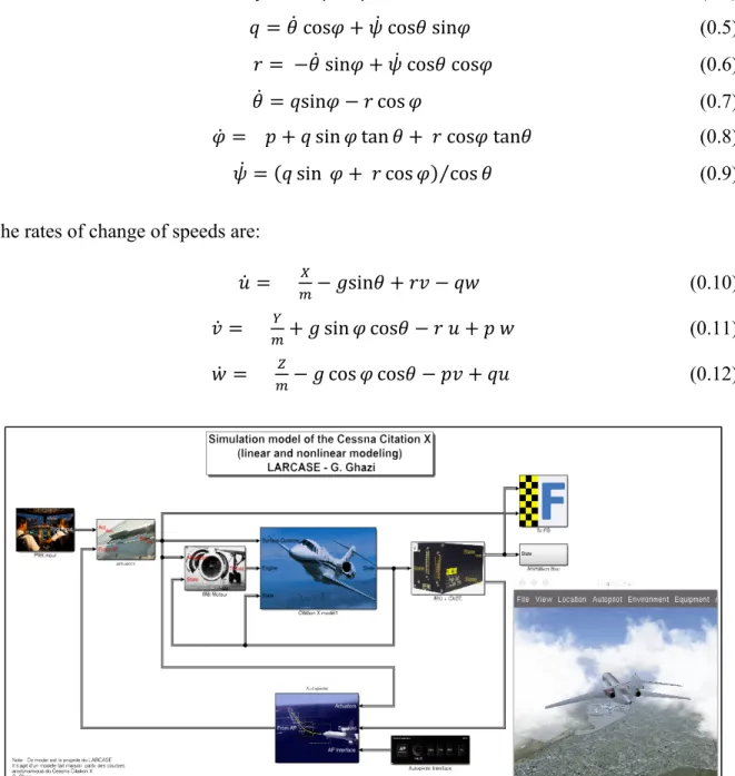
Figure 0-4 Simulation of linear and nonlinear model of the Cessna Citation X Taken from (Ghazi, 2014)
The simulations of a Cessna Citation X linear and nonlinear model are represented in Figure 0-4. To design a controller for any aircraft, a linearization of the nonlinear aircraft model for
9
flight conditions within the flight envelope given by the designer is required as a first step. Following the decoupling of the linearized aircraft motion into longitudinal and lateral motions, the equations are represented in the form of the following state space system:
= + (0.13)
The aircraft’s longitudinal motion dynamics are given by the state space equation, using the elevator deflection as input:
= + = + + + − cos 0 0 0 0 1 0 , = + 0 (0.14)
where the state vector ( ) and the control vector (t) are given by:
( ) = ( ) ( ) = (0.15)
The aircraft’s lateral motion dynamics are given by the state space equation, using the aileron and the rudder as deflection inputs:
= + = ⁄ ⁄ −(1 − ⁄ ) cos ⁄ 0 0 0 1 0 0 , = ⁄ 0 ⁄ 0 (0.16)
10
where the state vector ( ) and control vector ( )are given by:
( ) = ( ) , ( ) = ( ) (0.17)
The linearized model of the Cessna Citation X was obtained for 36 flight conditions using the Cessna Citation X Aircraft Flight Research Simulator tests performed at the LARCASE (Hamel, 2013). The linearized model is further decomposed into Linear Fractional Representation LFR models (Poussot-Vassal et Roos, 2011) using the bilinear interpolation
method. Thus, these LFR models were obtained for 72 flight points expressed in terms of
TAS and altitude, for 12 weight conditions as described in the following section.
0.3.3 Flight envelope using LFR models design by flight point’s interpolation
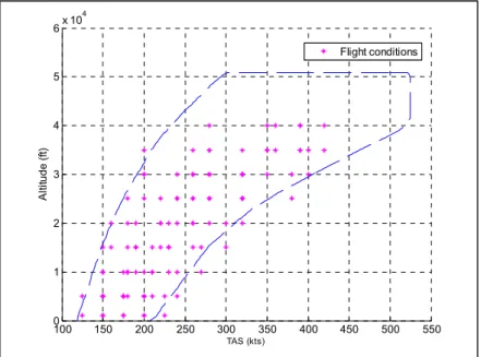
The linear models’ interpolation using Linear Fractional Transformation (LFT) facilitates the calculation of the state space matrices’ variation with the altitude and the TAS (Poussot-Vassal et Roos, 2011). Given the data extracted from the Research Aircraft Flight Simulator provided by CAE Inc., the aircraft flight dynamics can be described for any flight condition in the flight envelope. Figure 0-5 shows the 36 flight points selected inside the flight envelope limits. These aircraft models are obtained at each 5000 ft. in altitude for 4 different speeds.
11
Figure 0-5 Cessna Citation X flight enveloppe
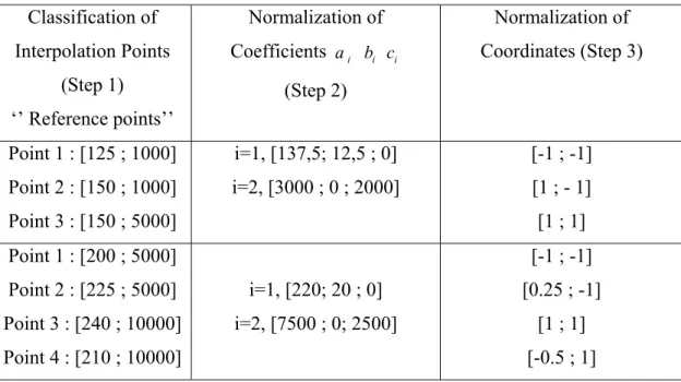
Before carrying out the interpolation, two steps need to be performed. The first step involves the definition of the region where the interpolation will be performed, for an altitude and a range of TAS, and for which the four corners of the region form the vertices. Each of these regions has lower and upper values which are defined as “bounds”. The second step concerns the normalization of these bounds in order to assign a value equal to 1 or -1 to each coordinate of the vertices.
To maximize the accuracy level, the smallest possible regions have been defined, containing only 3 or 4 flight points to use as reference points for the interpolation. This definition only allows a “bilinear interpolation”, for which four coefficients have to be found for each state space matrix, using equations (0.18), (0.19), and (0.20):
(ℎ, ) = , + , ℎ + , + , × ℎ (0.18) (ℎ, ) = , + , ℎ + , + , × ℎ (0.19) (ℎ, ) = , + , ℎ + , + , × ℎ (0.20)
12
Where A is a matrix of 4 rows and 4 columns, BLong is a matrix of 4 rows and 1 column, and
Blat is a matrix of 4 rows and 2 columns. The Least Square (LS) method is employed to
minimize the relative error in these reference points.
From these results, 26 regions that cover a large part of the flight envelope are obtained, denoted by rectangles in Figure 0-5. The mesh is valid for all of the weight and XCG locations presented in Figure 0-7. It can be observed from Figure 0-6 that some of the regions superimpose other regions (darker zones) due to their common reference points; for some regions, not only are their interpolations considered, but also their extrapolations.
These 26 regions’ vertices lead to 72 different flight conditions obtained by means of the LFR models; these cover more space in the flight envelope, as shown in Figure 0-8.
13
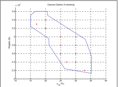
Figure 0-7 Cessna Citation X Weight/ XCG conditions
Figure 0-8 Flight points obtained by use of LFR models 0.3.4 Stability analysis interface
In order to accomplish the stability analysis, a Graphical User Interface (GUI) is used. It offers a wide choice of resolutions via three methods from published research found in (Wang et Balakrishnan, 2002), (Dettori et Scherer, 2000), and (Fu et Dasgupta, 2000). Figure
10 15 20 25 30 35 40 2 2.2 2.4 2.6 2.8 3 3.2 3.4 3.6
x 104 Cessna Citation X centering
Wei ght s ( lb) x cg (%) 100 150 200 250 300 350 400 450 500 550 0 1 2 3 4 5 6x 10 4 TAS (kts) A lti tude ( ft) Flight conditions
14
0-9 shows the window with which the user interacts; a brief description of how to manipulate the GUI is given in the following paragraph.
The GUI has two main sections; the first one is "Analysis", which contains the LFR models in “Model”, three methods for resolution in “Method”, the region that will be analyzed in “Region definition”, and “Approach”, which contains all the functions called during the analysis, classified as “ Progressive” or “Adaptive”, and the type of “Lyapunov Function”. The second section is the "Results", which stores the results data. The GUI has access to the LFR Toolbox, and to the YALMIP SDPT3.7.
Figure 0-9 Robust Stability Toolbox
To perform the stability analysis, the desired LFR model is first selected, and then the analysis parameters method (FD, DS, and WB), which can be one of the three main methods (Wang et Balakrishnan, 2002), (Dettori et Scherer, 2000), and(Fu et Dasgupta, 2000), is
15
carried out, followed by the normalization of the selected region, and then some other options such as choosing the discretization number, the Lyapunov function or the approach type. Once these parameters are chosen, the stability analyses can be performed for the selected region.
CHAPITRE 1
LITTERATURE REVIEW
1.1 Aircraft Flight Control System
Flight Control System (FCS) is designed to achieve higher aircraft performance with better or acceptable flying qualities within the flight envelope specified by the designer (Pahle et al., 1996). Classical control methods usually considered Single Input, Single Output (SISO) systems for flight control while aircraft control systems required several actuators simultaneously. Thus, Multi-Inputs Multi-Outputs (MIMO) systems are of interest for designing modern control methods using the state space systems. Lacking of knowledge in FCS will limit the development of an optimal controller with high performance FCS.
During the three last decades, modern control methods gained popularity over classical methods, for their efficiency in handling Multi-Inputs Multi-Outputs (MIMO) systems especially in the aeronautical industry (Nelson, 1997b). These modern control methods were applied on the Flight By Wire (FBW) airplanes.
Use of the state space (modern control) in FBW controls does not involve complexity in computer computation, allowing improved the flight safety while reducing the pilot workload, the mechanical parts, and real time monitoring of all aircraft systems’ (Samad et Annaswamy, 2011).
1.2 Flight Control Optimization
The state space equations are used for wide range of control methods (Friedland, 2012),(Skogestad et Postlethwaite, 2007). The design of optimal flight controllers relies on selecting the appropriate control method, which in turn depends on the aircraft type (civil or military), and its performance requirements (Roskam, 1985). The most popular methods are:
18
the Linear Quadratic Regulation Method and t the H-infinity method that is generally used to consider aircraft robustness requirements.
1.3 Linear Quadratic Regulation (LQR)
The advantage of the Linear Quadratic Regulation (LQR) method is that it provides the smallest possible error to both inputs and outputs while minimizing the control effort; the error corresponds to the difference between the desired and obtained value for system input and output.
In the case when the full states are measurable, the LQR method ensures a stable controller output for the nominal model, and it provides cross-terms in the flight dynamics equations. Consequently, it leads to a robust controller in the sense that the gain margin is infinite and the phase margin is greater than 60 degrees. It was illustrated in the literature by Boughari et al (2012) that LQR method has been used for the Stability Augmentation System (SAS) control, and applied on Hawker 800XP business aircraft.
In addition, the Linear Quadratic Gaussian (LQG) method has been used in (Botez et al., 2001) bomber B-52 aircraft to alleviate the gust effects. The LQR method has also been used in a longitudinal attitude controller designed for B747 aircraft (Guilong et al., 2013), and in adaptive LQR gain scheduling control is designed for remotely controlled aircraft (Mukherjee et Pieper, 2000).
In order to obtain corresponding optimal state feedback gain K in the LQR control methodology, the objective function which represents the quadratic performance index function J must be defined. This means the appropriate Q and R weighting matrices need to be estimated by a trial and error method, or by relying on the designer’s knowledge until the desired response is found.
19
In order to overcome the time-consuming LQR procedure, many algorithms were developed in the last decade to optimize the LQR weighting matrices searches. Use of stochastic searching as an optimization algorithm is one of the most popular methods that have been used recently; in (Wongsathan et Sirima, 2008) , (Wongsathan et Sirima, 2009), used stochastic search method to determine LQR weighting matrices to control an inverted pendulum, and then a triple inverted pendulum. Satisfactory results were obtained by comparison of the optimal Q and R matrices with the weighting matrices obtained through “trial and error”. The optimized LQR methodology using the Genetic Algorithm (GA) was applied on the buck converter to improve its voltage control response, and the distillation column control, respectively shown in (Poodeh et al., 2007) and (Jones et Hengue, 2009). In both of those cases, the control performances that is given by weighting matrices found with a GA search provided better results than those found experimentally.
(Ghoreishi et Nekoui, 2012) used both the Genetic Algorithm (GA) and Particle Swarm Optimization (PSO) algorithms with the LQR optimization. Guo et al used optimal LQR weighting matrices analyses based on the Genetic Algorithm (GA) search (Guo et al., 2010). Stochastic search for optimal LQR control combined with integral quadratic constraints was investigated by (Lim et Zhou, 1999); while Xiong et al. (Xiong et Wan, 2010) used LQR method based on PSO algorithm for double inverted pendulum control. In (Yoon Joon et Kyung Ho, 1997), the authors investigated stochastic searching methods for the determination of the LQR weighting parameters used for nuclear reactor power control.
In (Zhu et Li, 2003), the authors have used an iterative method for solving stochastic Riccati differential equations of the LQR problem. Unfortunately, the LQR control can only provide a stability augmentation to the system, in order to perform the tracking error; a classical control method is added by using a PID control.
The PID control gain can be tuned using an ad hoc method or can be optimized using a stochastic algorithm. As illustrated by (Mitsukura, Yamamoto et Kaneda, 1997), the tuning of PID gain parameters was based on the GA, and on Fuzzy Logic in (Hyung-Soo et al.,
20
1999). Han, Luo et Yang (Han, Luo et Yang, 2005), used a nonlinear PID controller based on genetic tuning, while a self-tuning algorithm was investigated by the authors for linear PID controllers; this algorithm was based on frequency characteristics in (Chen, Wang et Wu, 2010). In (Chang-Hoon, Myung-Hyun et Ik-Soo, 1997), the authors have used the model identification by use of two Nyquist points to automate the PID controller tuning; in (Bandyopadhyay et Patranabis, 2001), an auto-tuning algorithm for PID controllers based on dead-beat format requirements was performed using the fuzzy inference method.
From previous researches, we can deduce that these optimized LQR and PID algorithms were mainly used in chemical industries. There is a huge amount of flight tests to be managed in the aircraft control design, thus in the aerospace industry; for this reason there is a great need in the use of the optimization algorithms that can be performed on control parameters to meet the design requirements, and to save time, and thus money, which is a part of investigation in this thesis.
1.4 H-infinity Controller
The aircraft’s safety is dependent on its controller, as the clearance authorities need to ensure that the controller operates properly through the specified flight envelope even in presence of uncertainties related to mass, center of gravity positions, and inertia variations. The control clearance process is a fastidious and expensive task, especially for modern aircrafts that need to achieve high performance (C. Fielding, 2002) . This process aims to prove that the stability, robustness and handling requirements are satisfied against any possible uncertainties.
During the industrial clearance process, the selection of the appropriate control laws with sufficient robustness involves: the investigation of the closed-loop eigenvalues, the stability margins and the performance indices, in the presence of uncertainties. The resulting control laws are used further for the design of the Flight Control System (FCS).
21
The aircraft controller determination is very complex. Nonlinear methods such as Fuzzy Logic and Neural Network methods have been applied for Aircraft Identification and Control (G. Kouba, 2009),(N. Boëly, 2009). The Non- Linear Hybrid Fuzzy Logic Control on a morphing wing was explored (Grigorie et al., 2012a),(Popov et al., 2010). Due to its complexity in the Aerospace Industry, the determination of the robust Flight Control System FCS is usually carried out using linear methods applied on linear models, and it is further validated on non-linear models. In the literature, many linear control methods were used to obtain a FCS by the combination of modern control LQR method, the classical PID control method, and evolutionary algorithms that were applied successfully on the whole flight envelope of the Cessna Citation X (Boughari. et al., 20014a). However, the use of the LQR method allowed the system stabilization, while the classical PID control method was used for the tracking problem. A FCS that stabilizes and can track the reference input while taking disturbances into account was obtained by using, the H-infinity linear method proposed by Zames in 1983 (Zames), that had gained popularity in guarantying system robustness in the presence of uncertainties. The H-infinity method has been used in the Aeronautical industry to develop controllers with the aim to meet the required system specifications and needs.
One of the most important aspects of this controller is the determination of the weighting functions (W and W ), which are very important in the gains calculation. There is no specific methodology to determine these weighting functions. The literature points out that the weighting functions are determined using a trial-an-error methodology, or pure experience-based methods.
Several applications of this control method have been incorporated in the aeronautical domain, mostly for fighter jets, where a scheduled H-infinity controller was used for VSTOL longitudinal control (Hyde et Glover, 1993), and it has as well been used for the lateral control of an F-14 (G.J.Balas, 1998). An H-infinity controller design with gain scheduling approach was successfully used on a flexible aircraft where the weighting functions were not optimized, but were determined using Engineering intuition (Aouf, Boulet et Botez, 2002).
22
To overcome this lack of reference formulas, some guidelines were given in (Ciann-Dong, Hann-Shing et Shin-Whar, 1994b; Hu, Bohn et Wu, 1999) to determine these weighting functions. However, due to their trial and error nature the guidelines procedures may need many iterations to find acceptable results. Besides, the guidelines do not guarantee the fulfillment of the required control conditions. For this reason, a methodology to tune the weighting functions to meet the mandatory requirements is necessary.
There exist several weighting optimization methods based on mathematical algorithms, in which trade-offs were established between maximizing the stability margin and minimizing the H-infinity norm of the closed loop transfer function (Lanzon, 2005). These algorithms often performed on frequency-dependent optimizations, in which the iteration process demanded a considerable amount of memory allocation. To overcome this frequency-dependent optimization memory, a state space weight optimization was developed in (Osinuga, Patra et Lanzon, 2012b). However, that algorithm does not guarantee a global minimum convergence, which could lead to a poor stability margin, that could have a negative effect on a system operating in a large envelope, such as an aircraft.
A new and innovative methodology by taking advantage of both GA and DE algorithms to optimize the H-infinity weighting functions to develop a controller that satisfies the imposed dynamic specifications and the industrial needs is proposed in this thesis. This new approach can solve the clearance problem by reducing the complexity of needed calculations and their validation. However, this research confirms that optimization using the DE algorithm is more efficient and accurate than the optimization using the GA; Storn and Price (Storn et Price, 1997) have also shown the efficiency of the DE algorithm by the comparison of its results with genetic algorithm results.
Many global optimizations based on evolutionary principles have been used in the Control Engineering field. In the Aeronautical field, aircraft trajectory optimizations based stochastic search, such as the Genetic Algorithm (GA) were performed on several civil aircrafts (Murrieta-Mendoza et Botez, 2015a),(Patrón et Botez, 2015) as well as parameters estimation
23
methodologies were performed on autonomous air vehicles and in the flight testing of the aircraft intelligent flight controls (Mario, 1999),(Osinuga, Patra et Lanzon, 2012a). These new methodologies for the control of different parameters are applied in this thesis for the flight dynamics and control of the business aircraft Cessna Citation X model.
All these methods were developed in this thesis with the aim of reducing the computational complexity, and thus their time of convergence while achieving very good results. The GA and the Differential Evolution (DE) algorithms were selected to optimize the weighting function parameters.
1.5 Aircraft Clearance Criteria
The certification of an aircraft is an important and essential step in the process leading to its first flight. To prove that an aircraft is ready to fly, it must meet several criteria required by various agencies such as Transport Canada, the Federal Aviation Administration (FAA), or the European Aviation Safety Agency (EASA), and for a multitude of flight combinations in terms of center of gravity position, mass, speed, altitude and angle of attack. As in the case of any aircraft design or production process, the Flight Control Laws (FCL) have to be qualified, cleared and certified (C. Fielding, 2002).
Over the last few decades, very much research has been done to identify the FCLs’ clearance criteria (Deutschland, 2003), (De Oliveira et Puyou, 2011), (Goupil et Puyou, 2013). Some of these criteria have been reformulated as robustness criteria (Popov et al., 2010), (Boughari. al., 2012, Boughari et al. 2014b, Boughari et al.2016, Ghazi et Botez, 2015). For example the target criteria for the Airbus team are the stability, turbulence, comfort and maneuver criteria (Puyou, 2007), (Favre, 1994). All of these criteria have to be evaluated in the full flight envelope for all weight and XCG configurations.
A simulation technique for a flight envelope grid is commonly used. In this technique, for each grid point, the model simulation verifies if the specifications are (or not) satisfied
24
(Garulli et al., 2010). The main disadvantages of this technique are two-fold; firstly only local results following a partial study are obtained, and therefore, despite a significant density of the number of points, it is always possible to neglect the most critical flight cases. Secondly, the technique’s execution time depends directly on the required accuracy, and therefore on the grid refinement. However, due to the time involved and the considerable design cost, analyzing a full envelope model is not feasible in this thesis because of the infinite number of cases contained within the flight envelope and the weight/ XCG configurations.
To enable the use of rapid, comprehensive and effective analysis methods, parameter-varying models have been developed by incorporating their variations, also known as “uncertainties” in nominal models. These models were built for several flying conditions, and have led to the design of a new parametric method called Linear Fractional Transformation (LFT) (Becker et Packard, 1994b), (Zhou, Doyle et Glover, 1996). The use of such a method has gained the attention of aeronautical companies. It provided results which indicate to the industry that it has a promising future for the modeling of control laws’ design and certification (Bates, Kureemun et Mannchen, 2003), as it is expected to reduce the number of required flight maneuvers (Puyou et Losser, 2012).
Several methods were investigated as they were used for the generation of LFT parametric models (Yan et Moore, 1996), (Cockburn et Morton, 1997), (Cockburn, 2000), (Hecker et Varga, 2003). LFT is based primarily on the way in which different types of uncertainties in the dynamic model are incorporated. For example, a parametric multiplicative uncertainty was incorporated by applying multiplicative uncertainty for a robust Gust Load Alleviation of B-52 aircraft, and analyzed using mu –synthesis (Aouf, Boulet et Botez, 2002). One of the two forms of uncertainties structures: unknown “unstructured” or well-defined, known as “structured uncertainties” must be chosen. These types of uncertainties have been investigated for the stabilization problem, and were further illustrated for the thrust vectoring aircraft (Ibrir et Botez, 2005).
25
The LFT represents one of the more challenging methods for the incorporation of aerodynamic uncertainties (Marcos et al., 2010), (Szabó et al., 2011) or of the XCG, mass and inertia variations in the aircraft model. Several approaches for obtaining a good quality and reduced order of LFT models have been investigated, based on the number and complexity of parametric uncertainties (Varga et al., 1998), (Varga et Looye, 1999).
In the flight clearance process, an aircraft system with parameter uncertainties has been transformed into an LFR model using LFT, as shown in (Tang, Wei et Meng, 2011), where a robustness analysis was performed on an unmanned helicopter flight using μ-analysis. In (Shuai et al., 2013), the H-infinity control method was used for the flight clearance of a longitudinal aircraft model that had parametric uncertainties.
Flight control clearance criteria have become the focus of many studies conducted by universities and industries in the Group for Aeronautical Research and Technology in EUROPE GARTEUR project (Fielding et al., 2002). These studies were performed mainly on three aircraft fighter models, the High Incidence Research Model with feedback control HIRM+ which is a generic model, the Aero Data Model In Research Environment ADMIRE, and high performance short take off and vertical landing aircraft model called HWEM. Flight control clearance criteria has become the focus of many studies, including studies conducted by a group of universities and industries in the Group for Aeronautical Research and Technology in EUROPE GARTEUR project (Fielding et al., 2002).
These studies were performed mainly on three aircraft fighter models, the High Incidence Research Model with feedback control HIRM+ which is a generic model, the Aero Data Model In Research Environment ADMIRE, and high performance short take off and vertical landing aircraft model called HWEM, which are both realistic models. However, the flight control clearance criteria analysis results were mainly published for the HIRM+ generic model, and suggested adaptations of these criteria to civil aircrafts were only briefly discussed. Due to the lack of access to real flight control clearance data and the availability
26
of a level D Research Aircraft Flight Simulator, we were motivated to investigate the flight control clearance for a realistic Cessna Citation X business aircraft model.
1.6 Linear Stability Criteria
Due to the high volume of the flight clearance criteria, the “Eigenvalue Stability” criterion was selected to be investigated during this present research (Baldelli, Lind et Brenner, 2005). This criterion is expressed by a robustness analysis which was investigated at the LARCASE on both civil and military aircrafts: the HIRM, and the Hawker 800XP by using the weighting functions method (Anton, Botez et Popescu, 2013), (Anton et Botez, 2015). Normally this criterion has to be performed on the longitudinal aircraft closed loop control model to test its reliability during the aircraft flight in the presence of uncertainties. It searches through the aircraft envelope for eigenvalues with a negative real part. To evaluate this criterion, the results are compared with the natural stability of the aircraft, which means the eigenvalues for the longitudinal open loop model.
Our research shown in this thesis focuses on the Cessna Citation X open loop stability analysis. The data are provided by a level D Research Aircraft Flight Simulator; this level corresponds to the highest level flight dynamics certification and developed by CAE Inc. These data were used to develop both nonlinear and linear models of the airplane for its longitudinal and lateral motions (G.Ghazi, 2014), and to create longitudinal LFR models for 12 XCG and weight configurations of the whole flight envelope using a user-friendly GUI developed during this study to automate the LFR model generation. The LFR models were further analyzed with the robustness and stability analysis toolboxes to assess the aircraft open loop stability.
1.7 Cessna Citation X Clearance Criteria Evaluation
The clearance of the flight control laws of a civil aircraft is a fastidious task, especially for modern aircrafts that need to achieve high performance (C. Fielding, 2002). This process aims to prove that the selected stability, robustness and handling requirements are satisfied
27
against any possible uncertainties. Because of the numerous flight test data, the parameters variations, and their uncertainties have to be provided for the clearance of the large flight envelope. To carry out this process, a detailed description of methods and procedures, which are currently used in industry, was given in (C. Fielding, 2002).
As mentioned also in the other sub-section, the presence of uncertainties is related to many factors, that are mainly dues to the mass and XCG variations, aerodynamics data, control surfaces dynamics and delays, and Air Data measurements errors. To demonstrate the effects of important uncertainties, the clearance criteria are considered as robustness criteria from the Airbus team point of view (Deutschland, 2003), and were applied in linear, and nonlinear models and simulation (C. Fielding, 2002), (Seiler, Balas et Packard, 2012), and (Vincent et al., 2012).
In this thesis, the linear and the nonlinear clearance analysis of the Cessna Citation X business aircraft is addressed and evaluated for the first time, which gives to the reader a very good understanding of the criteria and visualization tools used in the assessment and clearance of the Flight Control Laws (FCL’s).
CHAPITRE 2
APPROACH AND ORGANIZATION OF THE THESIS
The research presented in this thesis was performed in four main phases, which are detailed in the following four chapters from Chapter 3 to Chapter 6 subsequently:
Stability Analysis of the Cessna Citation X Business Aircraft;
Aircraft Control Design and Optimization of Flight Control Laws (FCL) Design using a combination of the modern Linear Quadratic Regulator (LQR) control method, the Proportional Integral (PI) classical control methods, and the differential evolution algorithm;
Aircraft Control Design and Optimization of the FCL design using the advanced
H-infinity robust control method; and
Evaluations of the Linear and Non-Linear Clearance Criteria for the Cessna Citation X
During the first phase, a set of linear flight conditions composed of 36 points extracted from the flight test data performed on a level D Flight Simulator Research were interpolated using the Linear Fractional Transformation (LFT) method to create a larger database that covered the whole flight envelope, with a total of 72 flight points. This new database was used in the linear FCL design and validation for the whole research project. The Eigenvalue stability of the Cessna Citation X was also analyzed in this phase. The dynamic stability analysis of the whole Cessna Citation aircraft flight envelope using the Lyapunov function was performed on a Graphical User Interface (GUI), developed to automate the Linear Fractional Representation (LFR) generation in three ways (manual, visual, and direct). This LFR generation employed the altitude; True Air Speed TAS and Weight/Xcg were employed as uncertainties. The stability analysis was performed for a total of 12 Weight and Center of Gravity (Xcg) configurations in Chapter 3.
In the second phase, the Aircraft Flight Control System (FCS) design architecture was identified using the modern LQR control method for the Stability Augmentation System
30
(SAS), and then with the PI control method for error tracking. The handling qualities’ requirements for the Cessna Citation X were imposed as constraints for the controller optimization and design.
The LQR and PI control laws were optimized using a ‘Differential Evolution’ (DE) stochastic search algorithm. The results obtained during this optimization were validated for both the linear and nonlinear models of a Cessna Citation X business aircraft. Robustness stability analysis on the nonlinear aircraft model was performed for 12 Xcg and weight variations; good stability results were obtained for all of these variations In Chapter 4.
The third phase consisted of defining the aircraft’s controller architecture using the H-infinity modern control laws. This controller method was applied on both the Stability Augmentation System (SAS) and the Control Augmentation System (CAS) for an aircraft’s flight, and then the handling qualities were identified using the H-infinity controller. The controller design was further optimized using two different stochastic search algorithms, the Genetic Algorithm (GA) and the DE (using a methodology developed in the second phase).
The results obtained with these algorithms were compared during the controller design optimization, and its ‘linearized model’ controller validation. Following this comparison, the DE algorithm was chosen. It performed better than the GA in its design the H-infinity controller, which was then further used in the ‘nonlinear model’ controller validation. Robustness stability analysis was performed on the nonlinear model using a set of Xcg and weight variations, and very good stability results were obtained for this set of variations.
In the fourth and final phase presented in Chapter 4, the Cessna Citation X’s stability clearance linear and nonlinear criteria were evaluated for the designed flight controller using the optimized H-infinity control methodology. These linear and the nonlinear model stability analyses reveal that the optimal controller performs with an excellent stability in both cases.