PLASMA ACTUATION FOR ACTIVE CONTROL OF WIND TURBINE POWER
SHUBHANKAR GHOSH
DÉPARTEMENT DE GÉNIE MÉCANIQUE ÉCOLE POLYTECHNIQUE DE MONTRÉAL
MÉMOIRE PRÉSENTÉ EN VUE DE L'OBTENTION DU DIPLÔME DE MAÎTRISE ÈS SCIENCES APPLIQUÉES
(GÉNIE MÉCANIQUE) DÉCEMBRE 2011
ÉCOLE POLYTECHNIQUE DE MONTRÉAL
Ce mémoire intitulé :
PLASMA ACTUATION FOR ACTIVE CONTROL OF WIND TURBINE POWER
Présenté par : GHOSH Shubhankar
en vue de l’obtention du diplôme de : Maîtrise ès sciences appliquées et a été dûment accepté par le jury d’examen constitué de :
M. MUREITHI Njuki, Ph.D., président
M. VO Huu Duc, Ph.D., membre et directeur de recherche
M. MASSON Christian, Ph.D., membre et codirecteur de recherche M. LAURENDEAU Éric, Ph.D., membre
Acknowledgements
I would like to express my deepest gratitude to Prof. Huu-Duc Vo for his continuous guidance and support for me and my research. His suggestions and inputs have been extremely helpful in the shaping of this thesis. His advice related to all CFD- and experiment-related issues is highly appreciated.
I wish to thank Prof. Masson for his support and for sharing his expertise on wind turbines. His graduate course on wind turbine technology provided information that is indispensable to this thesis.
I would like to express my gratefulness to Philippe Versailles for having carried out the preliminary work which is the foundation of this research. I would also like to thank Xiaofei Xu for his contribution in the CFD implementation of the plasma actuator model and for his help with the plasma generation system.
Thanks are also due to Javad Hosseini, Mert Cevik and Catherine Mastrostefano for their help with the wind tunnel experiments. I also thank Eray Akcayoz and Engin Erler for helping maintain a pleasant work atmosphere in our office.
In the end, I would like to thank my parents for their support and patience over the last two years.
Résumé
Cette recherche évalue, optimise et démontre expérimentalement une nouvelle méthode pour réduire la portance et augmenter la traînée d’une pale de turbine éolienne pour contrôler la puissance éolienne à des vitesses de vent élevées. La méthode consiste à appliquer l’actionnement électro-fluidique du plasma pour accélérer la séparation de la couche limite sur les pales d’éolienne. L’effet de l’actionnement plasma sur un profil à deux dimensions d’éoliennes est d’abord évalué numériquement à de faibles nombres de Reynolds en utilisant un code commercial CFD auquel un modèle de l’actionneur plasma est intégré. Les résultats de ces simulations indiquent l’existence de conditions d’exploitation préférable pour l’actionneur plasma en termes de paramètres tel que sa force, la vitesse non-perturbée et sa position sens de la corde sur la pale. En ce qui concerne la force d’actionnement, il est constaté qu’il existe un seuil de la force au-delà duquel il y a un saut soudain dans la réduction de portance obtenue. Un bond semblable à l’effet d’actionnement est observé lorsque le nombre de Reynolds non-perturbé est réduit en deçà d’une certaine limite. L’existence de positions optimales pour l’actionneur plasma sur l’extrados de la pale est également observée. L’optimum est situé près du bord de fuite de l’aile pour les angles d’attaque avant le décrochage et il est déplacé en amont aux angles d’attaque près du décrochage et dépassés le décrochage. Toutes les simulations indiquent que la position de l’actionneur plasma par rapport au point de séparation de la couche limite est le facteur décisif à l’effet de l’actionneur sur la portance et la traînée. Ces simulations sont validées par des en soufflerie tests pour les mêmes conditions d’écoulement en soufflerie. Les mesures en soufflerie de la portance et la traînée se trouvent principalement à être cohérents avec les résultats de simulations. Le logiciel CFX validé expérimentalement est ensuite utilisé pour simuler l’écoulement à un Re réaliste pour les applications éoliennes. Cette étude montre que le niveau actuel de la force d’actionnement plasma est incapable d’exercer une influence perceptible sur les performances d’une éolienne. La théorie de l’élément de pale couplée à un bilan de quantité de mouvement est utilisée pour déterminer la quantité de la chute de portance qui serait nécessaire pour le fonctionnement à puissance nominale et cette exigence est comparée à l’impact de l’actuelle génération d’actionneurs plasma. Une tentative est faite pour estimer la force d’actionnement qui serait nécessaire pour réaliser la réduction de la puissance requise pour le fonctionnement nominal. Cette analyse montre qu’une force d’actionnement de deux ordres de grandeur serait nécessaire pour que le concept fonctionne sans l’aide d’un autre moyen de contrôle pour limiter la puissance des éoliennes. Cela implique qu’il doit être couplé avec une
autre méthode comme le contrôle de la vitesse du rotor pour avoir une possibilité réaliste d’application dans un proche avenir.
Abstract
This research evaluates, optimizes and experimentally demonstrates a new method to reduce the lift and increase the drag of a wind turbine blade for controlling the turbine power at high wind speeds. The method consists of applying electro-fluidic plasma actuation to accelerate the separation of boundary layer on the wind turbine blade. The effect of plasma actuation on a two-dimensional wind turbine profile is first assessed numerically at low Reynolds numbers Re using a commercial CFD code to which a plasma actuator model is integrated. The results from these simulations indicate the existence of preferred operating conditions for the plasma actuator in terms of parameters such as its strength, the free-stream velocity and its chordwise position on the blade. With respect to the actuation strength, it is found that there exists a threshold strength beyond which there is a sudden jump in the lift reduction obtained. A similar jump in the actuation effect is observed when the free-stream Reynolds number is reduced past a certain limit. The existence of optimal positions for the actuator on the suction side of the blade is also observed. The optimum is situated near the airfoil’s trailing edge for a pre-stall angle of attack and it is displaced upstream at stall and post-stall angles of attack. All the simulations indicate that the position of the actuator relative to the point of separation of the boundary layer is the key element in the actuator’s effect on lift and drag. These simulations are validated by testing for the same flow conditions in wind tunnel. The wind tunnel measurements of lift and drag replicate the trends seen in the simulations. The experimentally validated CFD tool is then used to simulate wind turbine flows at a realistic Reynolds number. This study shows that the current level of plasma actuation strength is incapable of exerting any discernable influence on the performance of a wind turbine blade. The blade element momentum theory is used to determine the amount of lift drop that would be required for rated power operation and this requirement is compared with the impact of the current generation of plasma actuators. An attempt is made at estimating the actuation strength that would be necessary to bring about the power reduction required for rated operation. This analysis shows that actuator strength of two orders of magnitude higher would be required for the concept to work on its own to limit wind turbine power. This implies that it must be coupled with another method such as rotor speed control to have a realistic chance of application in the near future.
Table of Contents
Acknowledgements ………... iii
Résumé .………. iv
Abstract ...………... vi
Table of Contents ...………... vii
List of Figures .……….. ix
List of Appendices .……….. xi
Chapter 1: Introduction …….……….... 1
1.1 Background ……...……….. 1
1.2 Problem Definition …..………... 2
1.2.1 Wind turbine Power Generation Explained with Blade Element Theory ………... 3
1.2.2 Boundary Layer control ..………... 4
1.3 Concept of Plasma Actuation ...………... 5
1.3.1 Previous Applications ...….………..…………... 6
1.4 Research Question …..………... 8
1.5 General and Specific Objectives ...……….. 8
1.6 Thesis Outline ………... 9
Chapter 2: Literature Review ………... 10
2.1 Wind Turbine Flow Control ………... 10
2.1.1 Passive Flow Control ………... 11
2.1.2 Active Flow Control ………... 12
2.2 Plasma Actuation ………...… 19
2.2.1 Development and Optimization of Plasma Actuator ………... 19
2.2.2 Counter-Flow Plasma Actuation ………... 21
2.3 Preliminary Assessment of Wind Turbine Blade Lift Control via Plasma Actuation ………... 27 2.4 Summary ………... 28 Chapter 3: Methodology ………... 30 3.1 Numerical Study ………... 32 3.2 Experimental Study ………... 36 3.2.1 Experimental Set-Up ………... 36 3.2.2 Plasma Actuator ………... 44
3.2.3 Lift and Drag Measurements ………... 46
3.3 Application at Realistic Conditions ………... 46
Chapter 4: Results and Discussion ………... 48
4.1 Computational Study ………... 48
4.2 Actuator Characterization ………... 49
4.3 Results ………... 51
4.3.1 Effect of Actuation Strength ………... 52
4.3.2 Effect of Reynolds Number ………... 56
4.3.3 Effect of Actuator Position ………... 59
4.4 Plasma Actuation at Full-Scale Conditions ………... 69
Chapter 5: Conclusions ………... 73
References ………... 75
List of Figures
1.1 Rise in the installed wind power capacity in the last decade [1] ………. 1
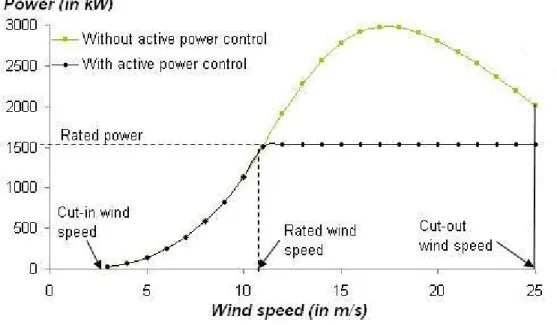
1.2 Typical power curve of a wind turbine ………... 2
1.3 Relative velocity and aerodynamic forces on a blade element ………... 3
1.4 Enhancement of flow separation by plasma actuation ………... 5
1.5 Schematic of a plasma actuator ………... 5
1.6 Smoke flow visualization (a) in absence, (b) in presence of actuation [25] …………... 8
2.1 Wind turbine flow control ………... 10
2.2 Influence of rotation on separation at different wind speeds [30] ………... 11
2.3 Illustration of variable diameter blade concept [32] ………... 14
2.4 Concept of trailing edge flaps [42] ………... 15
2.5 Active twist concept [42] ………... 15
2.6 Microtab concept ………... 15
2.7 Wind tunnel Cl & Cd curves for flap at full suction side deflection [47] …………... 16
2.8 Camber control with smart materials [48] ………... 16
2.9 Geometry of vortex generator jets [50] ………... 17
2.10 Side view of a synthetic jet [52] ………... 18
2.11 Laser sheet flow visualization of synthetic jet operation [53] ………... 18
2.12 Thrust per unit span vs. r.m.s. voltage for different dielectrics [59] ………... 20
2.13 Computed body force magnitude contours near the electrodes [68] ………... 24
2.14 Body force field computed with the model of Lemire et al. [15] ………... 26
2.15 Cl vs. angle of attack at 12.6 m/s [26] ………...… 28
3.1 Angle of attack variation vs. far-stream speed ………... 31
3.2 CFD domain used in simulations ………... 33
3.3 Sub-domain for plasma actuation ………... 34
3.4 Plasma force distribution (a) over sub-domain, (b) zoomed near the edge of the exposed electrode ………... 35
3.5 Assembly of all parts in the wind tunnel ………... 37
3.6 Set-up inside the wind tunnel ………... 37
3.7 Plasma generation system ………... 39
3.8 (a) Blade body's suction side, (b) Blade body's pressure side ………...… 40
3.10 Blade fitted with dielectric ………... 42
3.11 Variation of angle of attack ………... 43
3.12 Balance for measurement of aerodynamic forces ………... 43
3.13 Plexiglas dielectric cross-section ………... 44
3.14 Schematic of dielectric calibration set-up ………... 45
3.15 Control volume for body force computation ………... 45
4.1 Time evolution of lift ………... 49
4.2 Plot of actuation strength as a function of voltage ………... 50
4.3 Logarithmic plot for dielectric strength calibration in terms of voltage …………... 50
4.4 Cl & Cd from XFOIL, CFD & wind tunnel at speeds of 12.5 m/s & 30 m/s …... 51
4.5 Actuation strength effect on Cl at 12.5 m/s for 9.8 deg AoA (CFD) …………... 53
4.6 Actuation strength effect on Cl at 12.5 m/s for 9.8 deg AoA (wind tunnel) …... 53
4.7 Velocity field and the u=0 contour from CFD simulations for varying actuation strength at 12.5 m/s for 9.8 deg AoA ………... 55
4.8 Actuation effect on Cl and Cd with Re variation at strength of 30 mN/m …………... 57
4.9 Velocity fields at 9.8 deg AoA (a) at Re = 177000 (just before sharp drop in Cl) & (b) at Re = 140000 (just after sharp drop in Cl) ………... 57
4.10 Actuation effect on Cl and Cd with Re variation at strength of 150 mN/m …………... 58
4.11 Cl and Cd oscillations for high-strength actuation at very low velocity …………... 59
4.12 Location effect on Cl and Cd at 6.4 deg and 12.5 m/s at 30 mN/m strength …………... 61
4.13 Location effect on Cl and Cd at 9.8 deg and 12.5 m/s at 30 mN/m strength …………... 62
4.14 Location effect on Cl and Cd at 12.4 deg and 12.5 m/s at 30 mN/m strength …... 63
4.15 Velocity field at 6.4 deg AoA and 12.5 m/s for actuator at (a) x/c = 0.25, (b) x/c = 0.85 ………... 64
4.16 Extent of separation for (a) upstream (x/c = 0.25), (b) intermediate (x/c = 0.55) and (c) downstream (x/c = 0.85) actuator positions ………... 65
4.17 Location effect on Cl and Cd at 6.4 deg and 30 m/s at 150 mN/m strength …………... 66
4.18 Location effect on Cl and Cd at 9.8 deg and 30 m/s at 150 mN/m strength …………... 67
4.19 Location effect on Cl and Cd at 12.4 deg and 30 m/s at 150 mN/m strength …... 68
4.20 Performance curve of WINDPACT 1.5 MW wind turbine ………... 70
4.21 Lift reduction requirement vs. free-stream speed ………... 71
A.1 Validation of the Matlab code for turbine performance with WT_Perf …………... 83
List of Appendices
Appendix A: Prediction of Wind Turbine Performance Based on Blade Element Momentum
Theory ………... 81
CHAPTER 1
INTRODUCTION
1.1 BackgroundGlobal warming, geopolitical self-sufficiency based on energy security and rising prices of fossil fuels has increased pressure on companies and societies to turn to renewable energy. Of all the available sources, wind energy constitutes a source with great potential. In the past few decades, the evolution of wind energy has been sustained and rapid. It is in fact the fastest growing energy source, doubling its capacity every three years. At the end of 2009, the worldwide installed wind power capacity stood at 159 GW which rose to around 175 GW by mid-2010 and was expected to surpass 200 GW by the end of 2010. Currently, 340TWh of wind energy is being produced annually which is 2% of the worldwide electricity consumption [1].
Figure 1.1 Rise in the installed wind power capacity in the last decade [1]
Wind turbines have expanded both in size as well as capacity in the past few decades and continue to do so. The turbines of 25 years ago had diameters of the order of 15m and produced typically 50 KW whereas the turbines of today have rotor diameters in excess of 100m and can generate up to 5MW of power. There is enormous wind potential that still remains to be exploited, especially offshore wind energy.
However, in the current economic context, the relatively high cost of wind turbines is a significant barrier to their proliferation and can deter prospective investments into the wind
energy sector. As a result, wind energy is faced with the challenge of remaining commercially viable and cost-effective. This challenge also presents opportunities to improve and optimize various aspects of the wind energy technology.
The power control of wind turbines is one such major challenge. It is a major factor in their cost of acquisition and exploitation.
1.2 Problem Definition
The power characteristics of a typical horizontal-axis wind turbine are qualitatively similar to Figure 1.2. This figure illustrates the different regimes of operation of a wind turbine.
Figure 1.2 Typical power curve of a wind turbine
At speeds less than the cut-in speed, there is very little power being generated. For speeds greater than the cut-in speed, the power increases almost proportionally with respect to the cube of velocity in much the same way as the theoretical prediction. If left unchecked, this rise would continue till high values of velocity, at which point the blade begins to stall if the rotational speed is maintained constant. After a certain upper limit of the velocity, it is advisable to shut down the wind turbine to prevent damage to the rotor blade, the generator and other components. This upper limit is called the cut-out wind speed.
A wind turbine must produce electricity at the lowest possible cost. In this context, it is designed to produce maximum power or the rated power at an average wind speed of about 12.5 to 15 m/s (also called the rated wind speed), rather than for the stronger winds that come only a few times during the year and for which an optimal design of wind turbine would be more expensive. During strong winds, the turbine should not exceed its maximum design output to
avoid risking mechanical failure. Therefore, a reliable and economical technology to control the wind turbine power is required to enable a more widespread use of this clean energy source. 1.2.1. Wind Turbine Power Generation Explained with Blade Element Theory
Most modern horizontal-axis wind turbines (HAWTs) rely on the lift generated on the blades by the relative inflow of the wind to produce power. The blade element theory, which treats each rotor blade as a combination of several sections or elements and estimates the turbine performance from the superposition of the effects of these elements, permits the determination of the rotor power as a function of the lift and drag coefficients of the airfoil(s) in question.
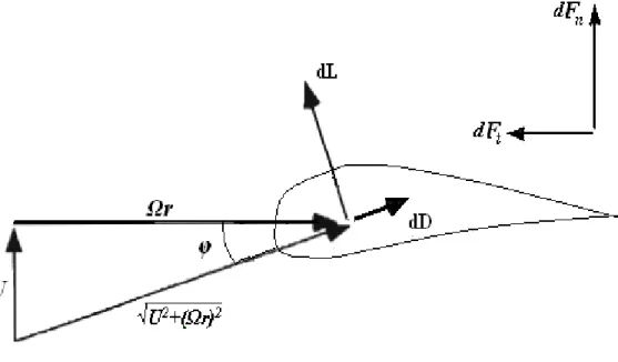
Figure 1.3 Relative velocity and aerodynamic forces on a blade element
Figure 1.3 shows the velocity and force vectors on a blade element of length dr, at a radial distance of r from the hub, rotating at an angular speed of Ω. The wind velocity at the blade rotor plane is U. It should be noted that this velocity is less than the free-stream velocity by a fraction called the axial induction factor. The relative speed Urel is, therefore, [U2+ (Ωr)2] 0.5
and is oriented at an angle φ from the plane of rotation. The differential drag dD and differential lift dL, being respectively parallel and perpendicular to this speed, are also inclined at φ to the plane of rotation and its normal.
dFn and dFt, the resultant force components in the normal and tangential directions
respectively, can be computed from the resultant of the components of dL and dD in the respective directions [2].
If B is the number of blades, the total differential torque dQ produced on the blade elements at a radial distance of r by the tangential force dFt is: dQ = B r dFt. The total torque Q
is given by Q = ∫dQ = B ∫r dFt and the power generated P is given by P = QΩ.
The above expression for the rotor power demonstrates that the power output of a wind turbine is a function of the lift and drag acting on the blades. A reduction of the lift and/or an enhancement of the drag bring(s) about a decrease in the power output. This is the working principle behind all aerodynamic methods of power control including deployment of flaps and pitching of blades.
1.2.2. Boundary Layer Control
Several techniques have so far been developed for the purpose of power and load control in wind turbines. Some of these techniques are based on controlling the boundary layer on the suction surface of the blade. As the near-wall flow moves downstream along the blade’s suction side, it encounters an adverse pressure gradient which weakens the boundary layer and may cause it to detach from the blade’s surface. Beyond a relatively high angle of attack, this phenomenon is intense enough to curtail the increase in lift that otherwise entails an increase in the angle of attack and a decrease in the lift coefficient follows. The airfoil, in this condition, is said to be stalled. If the boundary layer separation can be enhanced over an airfoil without increasing the angle of attack, the lift invariably drops for that particular angle. Boundary layer control is achieved by devices placed on the airfoil that are capable of manipulating the boundary layer, thereby affecting the pressure distribution and the lift and drag on the airfoil.
The present research intends to control the wind turbine rotor output power by using a plasma actuator on the blade suction side to add momentum in the upstream direction. Plasma actuators are discussed in detail in Section 1.3. This addition of momentum would induce or intensify suction side boundary layer separation, as shown in Figure 1.4, so as to limit blade lift and hence the power output at the high angles of attack associated with high wind conditions.
Figure 1.4 Enhancement of flow separation by plasma actuation
1.3 Concept of Plasma Actuation
Although there are various kinds of techniques currently employed for wind turbine power control, they all suffer from one or more drawbacks as discussed in the next chapter. This research proposes the novel technology of plasma actuation as a viable solution that is free from a lot of the practical restrictions, mechanical and economical, posed by the use of the conventional techniques. The potential of plasma actuators to address the problem is evaluated and analyzed in this project.
A typical DBD (dielectric barrier discharge) plasma actuator, the most common variety of plasma actuators, is an electro-fluidic device which consists of two thin electrodes arranged asymmetrically and parallel to each other, one electrode exposed to the air and the other one offset axially and fully hidden beneath a layer of dielectric material. Figure 1.5 is a schematic of an actuator configuration known as single dielectric barrier discharge or SDBD. When a radio frequency AC voltage signal of relatively low power but sufficiently high amplitude (O(kVpp)) is
applied across the electrodes, a weak ionization of the air takes place above the covered electrode with little or no heating. In presence of the electric field between the electrodes, the ionized particles, also called the plasma, experience an electric force and are accelerated. Their collision with the inert air particles results in momentum addition to the flow near the surface, equivalent to a body force acting on the air in motion. The magnitude of this force is quantified per unit of spanwise length under the name of plasma actuation strength and is measured in mN/m. In quiescent conditions, the effect of this body force is remarkably similar to a thin wall jet adjacent to the surface. More details on plasma actuators can be found in reference [3]. Plasma actuators are simple electric devices without any moving parts and consume very little power. Consequently, they are robust, easily integrable to existing structures and have higher bandwidth than mechanical actuators. Given that the electrodes have negligible thickness, plasma actuators can be made flush with the suction surface of the wind turbine blade, thus presenting a virtually non-intrusive solution to modify the effective aerodynamic shape of the wind turbine profile via the body force. For the purpose of this project, the axial position of the actuator is an important parameter. It should be noted that all the subsequent mentions of the actuator position in this thesis refer to the edge of the exposed electrode as shown in Figure 1.5.
The technology of plasma actuation has evolved considerably over the past few years. The following sub-section discusses the various applications where it has thus far been employed.
1.3.1. Previous Applications
Plasma actuators were first investigated by Roth et al. [4] in 2000. Since then, these actuators have been used for the control of leading edge boundary layer separation to maintain airfoil lift at high angles of attack and enhance lift at low and moderate angles of attack [5-11] by adding momentum in the direction of the incoming flow. These studies have used different actuator configurations, actuation locations and voltage wave-forms to delay flow separation but they have all dealt mostly with laminar flows of speeds ranging up to 30 m/s and produced similar results.
Plasma actuation was investigated for its ability to reduce the viscous drag in the case of a turbulent boundary layer in [12] with moderate success. Thomas et al., in [13], presented the results that they obtained from plasma actuation in order to streamline the flow past a cylindrical bluff body and to reduce noise.
In [14], Li et al. showed that upstream plasma forcing, located at ±90 deg on a circular cylinder with respect to the inflow, is quite effective in attenuating the noise from the wake flow interaction with an oblique downstream strut which is also a part of the bluff body. In another study [15] aimed at noise reduction, the results showed that continuous plasma actuation near the trailing edge can reduce the wake of a rotor considerably with relatively low power consumption and that the effect of the actuation is proportional to its strength.
In [16], plasma actuation was investigated for its potential to improve jet mixing. Huang et al., in [17], employed plasma actuation for the control of flow separation over blades in the low pressure turbine stage of a gas turbine engine at a Reynolds number typical of high altitude cruise. In [18], List et al. demonstrated the elimination of the separation bubble on a turbine blade in a linear cascade at low Reynolds numbers.
High flow turning in compressor stages [19] was achieved at a tip Mach number of 0.5 in a CFD assessment by Lemire et. al. Significant recovery of pressure was achieved in diffusers [20] with the help of spanwise acting plasma actuators generating a pair of streamwise vortices at the inlet section.
Moreover, plasma actuators have been studied for controlling tip clearance flow to increase turbine efficiency. In [21], the plasma force was oriented perpendicular to the camber line to resist the leakage flow through the tip gap. In the study carried out in [22], plasma actuation was found to bring about a 29.5% decrease in maximum pressure loss at a Reynolds number of 105 and a 14.7% decrease at a Reynolds number of 104.
The suppression of aerodynamic instabilities (criteria associated with spike rotating stall) in compressors with a plasma actuator was demonstrated in [23]. In their study, Li et al. [24] found that three plasma actuators placed at different chordwise positions on the endwall in a compressor cascade were most effective in reducing the pressure loss and flow blockage when operated simultaneously.
The above applications and some others have been discussed in greater detail in [5] and [25]. The impact of plasma actuation, as studied in [25], on an airflow that has separated past the leading edge of a flat plate is shown in Figure 1.6.
(a) (b)
Figure 1.6 Smoke flow visualization (a) in absence, (b) in presence of actuation [25]
1.4 Research Question
The basic question addressed in this work is whether plasma actuation is, by itself, capable of limiting the power of a MW (Megawatt)-class wind turbine. Moreover, what is the most optimal configuration (in terms of actuator location and strength) for power control using this concept and which are the conditions of flow incidence and velocity best suited for its application? A preliminary response to this research question was attempted in [26]. This work is discussed in more detail in Chapter 2.
1.5 General and Specific Objectives
The general objective of this project is to demonstrate the reduction of lift by plasma actuation on a 2-D profile of a wind turbine blade at low Reynolds number Re and estimate the effect on full-scale blades at realistic Reynolds numbers.
The specific objectives are stated below:
1. Assess numerically (CFD) the effectiveness of plasma actuators to influence lift on a 2-D wind turbine blade profile with respect to parameters such as actuator location and strength, flow incidence and velocity at low Reynolds number Re.
2. Validate experimentally the low Re numerical results in a wind tunnel.
3. Determine the effect of plasma actuation at realistic Reynolds numbers using a CFD code validated by wind tunnel testing.
4. Estimate the net change in lift from plasma actuation for a 3-D blade under high wind conditions from 2-D profile analysis.
1.6 Thesis Outline
This thesis consists of five chapters. The first chapter introduces the research problem and the concept of plasma actuation.
Chapter 2 contains a detailed review of the literature that describes the research that has been undertaken in the area of wind turbine power control along with the merits and demerits of each method. It also discusses the work that has thus far been done with regard to the development and computational modeling of plasma actuation.
Chapter 3 lays down the methodology that has been followed in order to achieve the goals of this research. It presents the details of the computational study comprising of the set-up of the CFD tool with the incorporation of the plasma actuator model and the experimental set-up which includes the plasma generation system and the test blade in the wind tunnel.
Chapter 4 contains the results from the parametric study of plasma actuators through numerical simulations and wind tunnel runs and a discussion on the implications of these results. It also studies the requirements of real-scale wind turbines in terms of power control and load reduction.
Chapter 5 gives an account of the conclusions of this study and suggestions for future work.
CHAPTER 2
LITERATURE REVIEW
This chapter presents an overview of the work that has been previously carried out by other researchers and which is fundamental to the current project. The preceding work can always be assigned to one of the following two categories:
1) Flow control methods over wind turbine blades, and 2) The technology of plasma actuation.
These are the two approaches that are adopted in this chapter to discuss the earlier research.
2.1 Wind Turbine Flow Control
The term flow control can be associated with any device or method that modifies a given flow field. Such alteration of the flow could be desirable for a variety of reasons, ranging from enhancement of lift to augmentation of mixing. The benefits of flow control are generally many fold and not mutually exclusive. In some cases, flow control employed for a particular benefit may also entail one or more undesirable effects on other properties of the flow. In these cases, a trade-off has to be made based on judgment.
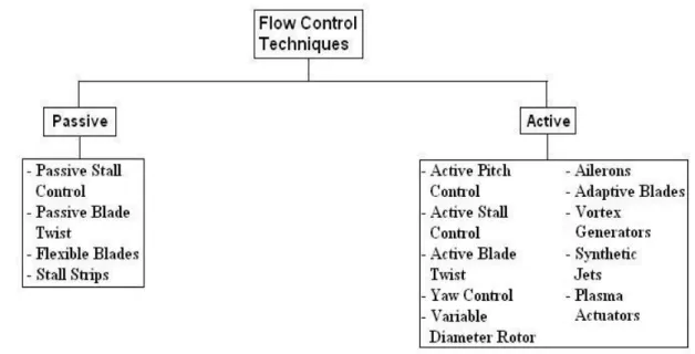
So far, the techniques employed for controlling the flow around commercial wind turbines and hence their electrical power output can be classified under two categories. These are passive control and active control as shown in Figure 2.1.
It should be noted that in the context of this project, the term ‘power control’ is used to imply a limitation of the rotor power during high winds and not the optimization of the rotor to maximize power in the case of moderate winds. The discussion that follows deals accordingly with controlling the flow to control or limit the turbine power.
2.1.1. Passive Flow Control
As the name suggests, passive flow control methods function without the supply of external energy [27]. Passive stall control is the simplest and most common of all such methods. Passive stall controlled blades rely on the intrinsic tendency of airfoil blades to stall, by the separation of the boundary layer on their upper surfaces, at higher angles of attack which are experienced at high wind velocities. The drop in the lift and the rise in the drag of stalled blades limit the power output of the turbines. These blades are designed and their pitches are fixed so as to attain the rated power at the desired wind speed. This method was used with reasonable success by earlier kW-sized wind turbines.
With no additional mechanical components involved, this method provides a cheap and reliable solution. But it comes with the associated uncertainty of the behavior of airfoils in stalled regimes. The contamination of dirt and insects at the leading edge of the blade may result in premature transition and turbulent separation of the boundary layer [28] which, in turn, could result in the wind turbine operating at a low efficiency in normal wind conditions due to premature stall. Moreover, the boundary layer on a profile in rotation behaves differently from that on a translating profile due to the Coriolis and centrifugal forces and often results in stall delay [29-31].
Figure 2.2 demonstrates the effect of the rotation on the separation point on a blade element at a particular spanwise position at different wind speeds. The effect of rotation is seen to be more conspicuous at low wind speeds. These difficulties may produce deviations of the order of tens of percent of the maximum power from the predictions, resulting sometimes in the stoppage of these turbines during high winds to avoid any damage. The economic losses associated with this phenomenon are estimated at 15% [29].
Passive blade twist is another flow control technique where the aeroelastic composite blade can alter its spanwise distribution of twist in response to aerodynamic forces. This method is however faced with challenges like waste of energy in normal winds, high costs and reduced structural integrity of the blade [32].
The use of flexible blades, also known as compliant blades, is another passive method where the blades shed the excess power in high speed winds by twisting towards the wind to reduce the angle of attack. Lee et al. [33] showed that these blades can eliminate the aerodynamic loads at the source. However, their design is a complex issue and they need a rather large twist to waste enough power for operation at rated specifications. The feathering requirement increases non-linearly from root to tip with a maximum of 30°-40° predicted for the tip by the simulation model.
Another technique is the placement of passive devices like stall strips, which are wedge shaped structures, near and parallel to the leading edge to induce flow separation. The results of Lewis et al. [34] showed that stall strips of a sufficient height can induce stall on the suction surface by acting as a trip for flow separation. Nevertheless, issues such as maintenance of tight tolerances between the strips and the blade surface and the possibility that the performance of the blade might be adversely affected by the presence of the strips [35] because of the drag penalty under normal wind-conditions, are serious obstacles to the implementation of this technique. 2.1.2. Active Flow Control
As opposed to passive control methods, active control methods actively modify the flow field by doing work or spending energy to a desired end while avoiding any major drag penalty. This energy has to be provided by an external source. There is a very obvious matter of profitability associated with active flow methods. Their use is justified only when their beneficial effects result in profits, monetary or otherwise, which are greater than the implementation and energy investments necessary for their operation.
An active control system is generally comprised of actuators and sensors placed spanwise over the blade. The sensors are meant to detect any changes that occur in the flow conditions
around the turbine. This acquired data is then transmitted for analysis to microprocessors which respond to the changes by instructing the actuators to apply the required displacements or strains which would counter the adverse effects of the changes [36].
Currently, the most widespread method of wind turbine power control is active blade pitch control [37]. It involves rotating the blade around its pivoting axis, via actuators in the hub of the rotor, so as to decrease the blade’s angle of attack with respect to the wind and thus control its lift and hence the power of the wind turbine during periods of high winds. A very similar method to the one mentioned above is active stall control. It is essentially the same principle but the power here is limited by pitching the blade into stall. The sense of rotation is opposite to pitch control and it is sometimes referred to as negative pitch control. These two methods also slow down the rotor because reduced lift and increased drag result in torque reduction for the blades. In a way, power is controlled in this case by a two-fold reduction in i) the blade torque, due to reduced lift and increased drag and ii) the reduced speed of the rotor.
The active pitch controlled blades enable superior control of the power output compared to active and passive stall machines because of greater unpredictability of the behaviour of post-stalled blades and allow operation at almost exactly the rated power. However, both active pitch and active stall control come with the drawback that they require expensive hydraulics or electric stepper motors with complex control mechanisms to position the angle of blades with precision [38]. These methods can add up to a significant fraction of the cost of a lower-power wind turbine, without even considering maintenance costs associated with the mechanism.
Besides the two aforementioned methods, numerous other active flow control devices and methods have so far been employed or are still being developed. These have been summarized in the discussion that follows.
Yaw control is a possibility for power control in small wind turbines generating a few kilowatts. The rotor is yawed out of the wind in order to capture less energy. But yawing results in increase in sound emission and in cyclic stresses on the rotor which could be potentially dangerous because of the possibility of fatigue failure of the entire structure.
Since the electrical power output of a wind turbine is directly proportional to the area swept by the rotor, variable diameter rotors [32] can be effective in controlling the power output. As shown in Figure 2.3, the rotor blade consists of a blade element that is extensible and retractable with respect to the main blade section. Operation at a smaller diameter beyond the rated wind speed would enable to limit the power production. Accounting for all the alterations that this concept would entail in a wind turbine, a reduction of 18% is predicted for the cost of
energy in [32]. With this technique, there are issues like complex control mechanisms and increased weight of the blades.
Figure 2.3 Illustration of variable diameter blade concept [32]
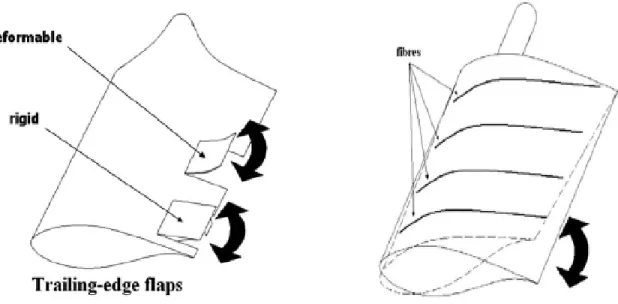
Ailerons, which are essentially flaps deployed by applying a moment at their hinges, were studied as an active technique to control lift by Miller et al. [39] who obtained interesting results in terms of braking capability with larger ailerons. These flaps can be either a separate entity or a deformable continuation at the trailing edge as shown in Figure 2.4. Studies of Lackner et al. [40] show that these trailing edge flaps are quite effective for fatigue load control. Their simulations resulted in reductions between 12 and 15% for the damage equivalent load of the blade root flapwise bending moment. But their effectiveness is subject to the system’s ability to react fast enough, by overcoming the inertia of the flaps, to changes in the ambient flow [41]. Moreover, the fabrication of ailerons and the associated actuation and control mechanism can be an unacceptable addition to the manufacturing and maintenance cost of the wind turbine. In addition, the mounting components are subject to wear and tear, the aerodynamic performance of the blade degrades due to an abrupt change in camber and the surface discontinuity can produce unwanted noise and cause stall during low winds [42].
Figure 2.4 Concept of trailing edge flaps [42] Figure 2.5 Active twist concept [42] Active twist of wind turbine blades is another way to alter the local angle of attack for power and load control. The effect is shown in Figure 2.5. The twisting is accomplished by active piezoelectric elements present in the blade and it is highest at the blade tip, where it is required the most [42]. This concept is faced with problems like reduced structural integrity, slowness of response due to inertia, high cost of the actuation components and inadequacy of the system to produce the necessary strains. It was shown in [43] that a strain as high as 800μ would be needed to produce a 4° twist at the tip of a 60 m wind turbine blade with a mean chord of 3.4 m and t/c ratio of 28%.
Figure 2.6 Microtab concept
The deployment of Gurney Flaps or microtabs projecting perpendicularly near the trailing edge of the airfoil is another option that has been investigated by van Dam et al. [44,45]. The schematic is shown in Figure 2.6. Their deployment effectively changes the camber of the airfoil and thus alters the aerodynamic forces on the blade. If placed on the suction side, they can be used to decrease lift, as is evident from the data in Figure 2.7. But they pose the risk of increased vibrations of the blade by causing unsteady shedding of counter-rotating vortices near the trailing edge. Moreover suction side flaps or tabs have been shown to reduce lift only for low and
moderate angles of attack. They are less effective at higher angles experienced during high winds since the flow has already separated upstream and is not affected by their presence [46].
Figure 2.7 Wind tunnel Cl and Cd curves for flap at full suction side deflection [47]
Adaptive blades are blades that are capable of modifying their camber and their overall shape in order to meet the control requirements. In this sense, they differ from actively twisted blades where the observed angle of attack is altered but the blade profile is not. They are similar to compliant blades, discussed in Section 2.1.1, but for the fact that the alteration of the profile is achieved by smart materials, such as piezoelectrics or shape memory alloys, embedded in the blade’s skin [48]. This is illustrated in Figure 2.8. A very thin skin section is imperative for this kind of control. Since the strains produced in this case are significant, a thin section may result in a breach of the structural integrity.
Although they have not been used for load or power control on wind turbines, active vortex generators, which are solid tabs on the airfoil surface, could be an interesting option in this respect. Barrett and Farokhi [49] performed wind tunnel experiments on a two-dimensional wing section to demonstrate a 14% increase in maximum lift, a 2.7 deg rise in the stall angle of attack and 42% jump in lift-to-drag ratio through stall using modern vortex generators. These benefits would have to be exploited by deploying the vortex generators during moderate winds enabling more extraction of power from the wind. Beyond the rated speed, they could be withdrawn to reduce the lift and hence control the power. However, the additional drag would be a significant drawback when the flow has not separated.
Vortex generator jets, which are jets of air coming out of the blade wall, are a similar but less intrusive technique that could be investigated. Figure 2.9 illustrates a schematic of the vortex generator jet configuration. As in the case of vortex generators mentioned above, these jets will have to be functional during normal winds and dormant during strong winds. Results from a parametric study [50] performed with such jets indicate that the level of flow control accomplished depends on the speed, the orientation with respect to the free-stream and the location of the jet with respect to the separation region.
Figure 2.9 Geometry of vortex generator jets [50]
The concept of lift enhancement by the addition of vortices in normal operation and their absence at high wind speeds can be extended to high-frequency micro vortex generators. In this case, vortices are added by the periodic movement of one or more mechanical elements. Lift increase on the order of 10%, drag reduction on the order of 50% and L/D ratio enhancement of 100% for a high lift airfoil was reported in [51] using these micro-vortex generators. Synthetic jets [52] work in a very similar manner. A schematic of a synthetic jet is presented in Figure 2.10. These jets were found to favour reattachment of separated boundary layers in [53]. The
mitigation of the extent of separation due to the operation of a synthetic jet can be observed in Figure 2.11. These methods are easy to integrate with the turbine blade but need tight tolerances and could potentially create noise.
Figure 2.10 Side view of a synthetic jet [52]
Figure 2.11 Laser sheet flow visualization of synthetic jet operation [53]
Most of the flow control devices, discussed above, have their merits and demerits and are still being researched. Before they are introduced as viable solutions to the problem of wind turbine power control, they need to be improved in various aspects and extensively tested on real wind turbines.
2.2 Plasma Actuation
Plasma actuators are finding newer avenues due to their capability of aerodynamic flow control. This section discusses the efforts for the development and optimization of plasma actuators. An overview of the research aimed at numerical modeling of the effect of actuation is also presented.
2.2.1. Development and Optimization of Plasma Actuator
Before they were introduced into aerodynamics, plasma actuators were used industrially for purposes like ozone generation and depollution of gas streams [54]. Subsequently aerodynamic applications have been tested and developed, the majority of which are based on the enhancement of the performance of aerodynamic profiles as opposed to the present research which seeks to reduce the lifting capability of such profiles. Since its inception, plasma actuation has witnessed extensive research efforts in terms of its optimization as well as its deployment on test surfaces. It finds such wide acceptance owing to its ease of construction, lack of moving parts, low power input, low cost, quick response time and little interference offered to the flow during idle periods due to their thinness.
Plasma actuation has proved to be quite versatile so far. It has lent itself to a large variety of applications because of its ability to influence the boundary layer by means of the wall jet that it induces very near the aerodynamic surface. The impact on the boundary layer is significant because the action of the jet is mostly in the length scale of the boundary layer. Numerous studies have been undertaken with the objective of examining the mechanism behind the production of the plasma body force that influences the boundary layer. In one such study [55], it was found that the magnitude of the force that models the effect of momentum transfer depends only on the electric field strength, ion density (number of ions available per unit volume for acceleration) and plasma volume and not on the density of the neutral particles (unionized molecules of gas). It was seen that all the momentum of the ions is transferred to the neutral particles irrespective of their density.
The majority of the previous work in plasma actuation has been limited to low and moderate Reynolds numbers (O(105)). This is because of the weak strength of actuation that has typically been achievable. Plasma actuators of strengths ranging from 20 to 40 mN/m have till now produced wall jets with maximum speeds of the order of a few m/s, which is suitable enough only for the modification of flows at low to moderate values of Re. The development of plasma actuators of higher strength, capable of inducing larger flow accelerations, is an active area of research.
Balcon et al. [56] found that negative sawtooth signals are more appropriate than positive sawtooth signals in terms of inducing homogenous and rapid airflows near aerodynamic surfaces. There have been attempts to enhance the actuation strength by varying different parameters of actuator geometry and configuration. In their study [57], Forte et al. observed higher flow velocities for greater lengths of the hidden electrode till a certain extent. It is likely that the increase takes place as long as the length of the hidden electrode is not sufficient for the spread of plasma and saturation is reached when this length is enough to accommodate the fully-expanded plasma.
Ideally, dielectrics having large dielectric constants and small thicknesses should be the best option to induce high values of thrust for a given input voltage [58]. But thin dielectrics come with the downside of having low dielectric strengths due to which the threat of arcing becomes more realistic at high voltages. Consequently, thicker materials are a safer choice for plasma generation despite the fact that they necessitate a higher input voltage. Thicker dielectrics with low dielectric constants end up producing higher values of maximum thrust because of their ability to operate at higher voltages without breaking down. This tendency is observed in Figure 2.12. Recent studies indicate that there has been an order of magnitude increase in the strength of actuators than what was previously achievable and body forces of about 200 mN/m are now possible using thicker dielectric materials of lower dielectric constants and higher AC voltages [59].
2.2.2. Counter-Flow Plasma Actuation
Studies on plasma actuators as counter flow devices have been very few and far between. The past research has dealt with counter-flow plasma actuation as just another variant of actuator configurations to be examined in order to achieve the same end as the co-flow actuation, viz. the suppression of stall and boundary layer separation.
Visbal et al. [60] were the first to operate the counter-flow actuator. They showed that the counter-flow actuator provided an effective tripping device for a laminar boundary layer developing along a flat plate and used this property to suppress laminar separation over a ramp. They however did measure reduction in the lift coefficient in the case of steady counter-flow actuation.
In [61], a velocity decrease was observed on the suction side of the wake of a compressor blade rotating at two different speeds 600 RPM and 350 RPM with the counter-flow actuator at ¼ chord. The effect of plasma actuation was to remove momentum from the flow on the suction side. The results of Benard et al. [62] indicated that counter-flow actuation, as opposed to its co-flow counterpart, was unsuitable to promote any substantial change in the mixing of a jet co-flow.
In the case of this thesis, counter-flow plasma actuation is always applied to a turbulent flow. In the computational simulations and wind tunnel experiments, the incoming laminar flow is forced to transition at 10% chord length and the actuation occurs some distance downstream. This arrangement is chosen so as not to reduce the plasma actuator to a flow tripping mechanism [60].
2.2.3. Computational Modeling of Plasma Actuator
Despite the rapid advances being made in the technology of plasma actuation, computational fluid dynamics (CFD) will play an instrumental role in the assessment of the capacity of plasma actuation to influence various airflows. It provides an inexpensive alternative in comparison to the building of test prototypes. New configurations of plasma actuation can be evaluated for their effectiveness using CFD before incurring any expenses for wind tunnel or full-scale testing. In order to numerically analyze the effect of plasma actuation, it is essential to have a well-defined model of the body force since the force has to be incorporated in the momentum conservation equations. The following sub-section deals with the efforts that have been made in the modeling of the body force.
The operation of a plasma actuator is simulated in a CFD code by modeling it with a spatial body force field. Several attempts have been made by researchers to develop models capable of closely reproducing the observations from experiments involving plasma actuation.
A study of the available literature indicates that the numerical modeling of plasma actuation has been accomplished primarily using one of two approaches, namely macroscopic and microscopic. The macroscopic models solve the global phenomena that take place during plasma actuation and simulate the momentum transfer to the flow with a spatial body force distribution that can be implemented as a source term in many CFD codes. On the other hand, the microscopic models solve for the effects of plasma actuators considering microscopic effects which include chemical reactions and collisions between ions, electrons and neutral particles.
One of the first efforts to numerically model plasma actuators was undertaken by Massines et al. [63]. The variations of the electric field in space and time were calculated along with the electron and ion densities from a one-dimensional model based on the continuity of the charged and excited particles and the Poisson equation. The discharge mechanisms involved were more clearly understood after this analysis. In [64], the time-dependent evolution of the potential and the electric field around two-dimensional objects during a high voltage pulse was studied. The numerical simulation was based on the solution of Poisson’s equation on a grid and the determination of the movement of the particles through it.
References [65] and [66] are exercises in the macroscopic or ‘phenomenological’ modeling of plasma actuator. This approach is more suitable in design and for implementation in CFD. Hall [65] applied plasma actuation as flaps on airfoils and wings using potential flow models as a first-order approach. The discharge physics was not taken into account. A doublet (source and sink) was selected to represent the plasma actuator in a free-stream. The doublet’s strength was calibrated using a relationship based on the local velocity at the point of actuation and it was incorporated into a Smith-Hess panel code. The experimental lift enhancement results were successfully reproduced with this model. This model however requires some inputs based on experimental observations in order to model the actuator with reasonable accuracy due to the fact that the actuator properties are not accounted for.
Shyy et al. [66] proposed a simple plasma actuator model characterized by a time-averaged (over an AC input cycle) linear two-dimensional body force distribution based on the size of the electrodes was presented. The parameters related to the electrode operation, including the voltage, frequency and free-stream speed, were varied to study the characteristics of the plasma-induced flow and the heat transfer. It was found that the induced flow velocities and heat flux varied proportionally with the applied frequency and voltage and that the electric field was greatest at the inner edge of the electrodes and decreased linearly as one moved away from it. This model was however faced with a few issues. First of all, the properties of the dielectric are
not taken into account. Secondly, the body force field generated by it is very much linear and does not present an accurate enough representation of plasma behavior seen experimentally. In addition, the computed body force strength differs considerably from experimental measurements for given values of voltage and frequency.
Suzen et al., in [67] and [68], proposed a more refined model which computes the body force vector by the spatial solution of two additional equations: one for the external electric field (or potential φ) due to the applied AC voltage at the electrodes and the other for the charge density ρc representing the ionized air. These equations are as follows:
(1)
2
(
c)
c/ d (2)
where ε is the local relative permittivity and λd is the Debye length (a plasma property
quantifying the extent of shielding of an external electric field from the interior of the plasma). The calculation of the electric potential and the charge density as a function of actuator input, electrode size/thickness and the nature and properties of the dielectric material generates a more realistic body force distribution which is then modulated in time according to the input AC voltage. This model however does not capture the experimentally observed unsteadiness in the plasma over an AC cycle. Figure 2.13 shows the contour plot for the magnitude of the body force in the vicinity of the electrodes computed using the model of Suzen et al.
Figure 2.13 Computed body force magnitude contours near the electrodes [68]
In the above figure, the highest magnitude of the body force is seen to be concentrated in the area over the upper corner of the concealed electrode. This is also true for the computed charge density and electric field strength. This finding is consistent with experimental observations of maximum plasma strength occurring in the same region. On the other hand, the model of Shyy et al. predicts the existence of maximum force magnitude some distance downstream over the concealed electrode where vertical force vectors, pointing towards the dielectric, predominate.
Orlov et al. [8,69] proposed a model incorporating more of the physics that governs plasma generation to obtain a more accurate time-variation of the body force during the AC input cycle. The dynamics of the glow discharge (plasma) region over the encapsulated (hidden) electrode was modelled using a network of electrical elements to obtain a more accurate spatial and time variation of the induced body force along the dielectric surface during the plasma generation cycle. However, the body force distribution resulting from this model was still not very realistic.
There are some more sophisticated models aiming to simulate the working of the actuator on a microscopic scale and involving more complicated chemistry. These models contain
numerous reaction equations with different reaction times and energy outputs. The equations account for reactions amongst the neutral and charged particles in different gases present in the air. The reaction equations are solved with those of fluid motion to obtain the actuator-generated force mostly in the case of a simple one-dimensional dielectric barrier discharge. Font et al. [70,71] took into account nitrogen and oxygen reactions in their model of the plasma discharge in the asymmetric plasma actuator. The propagation of a single streamer was shown from the bare electrode to the dielectric surface and back. In [72], the weakly ionized air plasma was modeled as a four-fluid mixture: neutral molecules, electrons, and positive and negative ions. The ionization and recombination processes were included. The charging of the dielectric by electrons during the avalanche ionization process was found to play a crucial role in DBD operation and gas acceleration.
Although modeling of the plasma actuator in micro scales is the most suitable approach to understand its physics, it tends to be very time-consuming and computationally intensive. Its application as a design tool for iterative optimization of plasma actuators and its implementation in CFD solvers to simulate macroscopic aerodynamic flows is not yet a feasible option.
According to Orlov et al. [8], for the flow velocities considered in most flow control studies with plasma actuators, the time scale associated with the flow response is six and two orders of magnitude slower than that associated with the ionization process and the AC input cycle respectively. Since the plasma formation process is virtually instantaneous from the point of view of the flow, a time-averaged spatial body force distribution approach can most effectively model plasma actuation. It captures the net spatial effect of the actuation on the flow near surface boundaries and the computational cost remains acceptable. No model has yet been developed which can produce a time-accurate distribution of the body force from the actuator geometry and input. In [63] however, it was shown that the proposed model of the body force could replicate experimental velocity profiles even if the magnitude of the body force may be inaccurate. A better conformation could be obtained with a more accurate body force distribution.
Lemire et al. [15] came up with a model which is coded in MATLAB and combines the best features of the models by Suzen et al. [68] and Orlov et al. [8,69] to simulate the plasma actuator as a time-averaged spatial body force distribution which resembles that obtained with one of the much more sophisticated scientific models [73] but is obtained from an engineering model. The corresponding body force distribution (per unit actuator length) is computed from equation (3), where A is the area of the mesh, after solving the model equations (1) and (2) to obtain the spatial
distributions of the electric potential and charge density on a very fine rectangular mesh. Figure 2.14 shows the time-averaged body force vectors in space.
(3)
Figure 2.14 Body force field computed with the model of Lemire et al. [15]. x and y are in mm. x = 0 is the edge of the exposed electrode and y = 0 represents the dielectric surface.
There is some qualitative resemblance between the force fields represented in Figure 2.13 and Figure 2.14 as far as the force magnitudes are concerned. The models of both Suzen et al. and Lemire et al. predict the occurrence of maximum force strength near the junction of the two electrodes and a gradual decrease in the force magnitude on moving away from this junction.
The force distribution is mapped onto the coarser CFD mesh of the actuator sub-domain in which the plasma actuator is placed using the method outlined by Lemire et al. [15]. The body force vectors are then scaled to obtain the desired total induced body force (actuator strength). This model does not claim to be able to exactly predict the spatial force distribution or the force magnitude but it claims to be able to predict a spatial force distribution that is comparable to the time-averaged distribution predicted by a microscopic model.
2.3 Preliminary Assessment of Wind Turbine Blade Lift Control via Plasma Actuation In a preliminary experimental and computational effort to evaluate the potential of plasma actuation to reduce the lift of a wind turbine airfoil [26], an actuator, injecting in the upstream direction, was installed on the suction side of the blade to induce and control the separation of the boundary layer. Experiments were carried out in a subsonic wind tunnel, at angles of attack in the range 0-15°, for velocities of 12.60 and 16.30 m/s, on a 6-inch chord untwisted 2-D blade having the DU 1996-W-180 profile. Details on this profile can be found in [74]. The plasma actuator was placed at 30% of the chord to induce an upstream flow and sand paper, placed at 10% of the chord, was used to trip the laminar boundary layer so that the flow past the blade would be turbulent as in real wind turbine cases. The aerodynamic balance force measurements showed a modest reduction of the order of 10% for the lift coefficient. Flow fields obtained by PIV demonstrated that depending on the angle of attack, the actuator thickens the boundary layer, induces or amplifies its separation. The CFD simulations reproduced the experimental trends. Figure 2.15 shows the reduction in lift that is observed both experimentally and numerically at an inlet speed of 12.6 m/s.
0.15 0.25 0.35 0.45 0.55 0.65 0.75 0.85 0.95 1.05 1.15 0 2 4 6 8 10 12 14 16 AOA (degrees) L ift C o eff.
Experimental (No actuation) Experimental (With actuation) CFX (No Actuation)
CFX (With actuation)
Figure 2.15 Cl vs. angle of attack at 12.6 m/s [26]
This thesis is based on the premise that lift reduction can be achieved by plasma actuation and investigates more thoroughly its potential and applicability in the context of real wind turbines. The behaviour of the flow in response to plasma actuation is investigated for a wider variety of conditions, which will be elucidated in the later chapters of this thesis, and applies to actuators of greater strength in flows of greater Reynolds numbers. The tools used in this project, namely CFD and wind tunnel testing, are the same as in [26] but they are used not only to demonstrate the reduction of lift but also to optimize certain flow parameters which are critical to the effectiveness of the actuator.
2.4 Summary
The literature review in this chapter examines the conventional practices that have been and are being employed to control the loading and electrical power output of wind turbines. Most of the existing techniques are based on the structural modification of the blade in some way or the other. Boundary layer control methods have not been comprehensively tested and applied. This research project aims to investigate plasma actuation as one such method.
The computational modeling of plasma actuation has been reviewed since it is indispensable to the CFD studies for optimization. The model, presented in [15], is chosen for
application in this research project after taking the merits and complications offered by a numerous models into account.
Finally, the preliminary work carried out in [26] is presented because this thesis builds upon the same philosophy. Some promising results were observed in this work, primarily demonstrating the possibility of lift reduction with plasma actuation.
CHAPTER 3
METHODOLOGY
In this chapter, the methodology is described for the following three phases of this research:
1) Numerical study
2) Experimental validation
3) Application in realistic conditions
The numerical study is aimed at simulating flow conditions that can be validated experimentally. The computational domain is a two-dimensional section of the wind tunnel which is used for experiments. The simulations are restricted to low Reynolds numbers and examine the aerodynamic response of the airfoil to plasma actuation under different flow conditions. These tendencies are expected to be present, although to a different extent, at real-scale Reynolds numbers too and give an insight as to how the operation of a plasma actuator may potentially be manipulated to obtain the best results in the course of its application on a wind turbine.
The second phase of this project comprises of the experimental validation of the results obtained computationally. The objective is to authenticate the use of ANSYS-CFX as a reliable tool for analysis of external flows on airfoils and the application of the integrated plasma body force model. The simulated cases in the first phase are all redone in the wind tunnel in the second phase.
The experimental validation of CFX is followed by its application to simulate high Reynolds number flows around full-scale 2-dimensional blades to assess the impact of the plasma actuator in such conditions. The lift reduction requirement is calculated and simulations are executed to predict the strength of actuation that would be necessary to achieve these levels of lift drop.
The wind turbine airfoil that is tested here is DU 96-W-180 [74]. This particular profile has a maximum thickness that is 18% of the chord length. It is a relatively thin member of the DU series of wind turbine airfoils and has a sharp trailing edge which makes it suitable for use at outboards of wind turbine blades. Given that the airflow past the blade has the least tendency to separate at its outboard and that the outward blade elements are the major contributors to wind turbine power, it is here that the conditions are the most adverse for plasma actuation to induce
separation. For this reason, this study focuses on the potential impact of plasma actuation at the blade tip.
Choice of Angle of Attack
The choice of angles of attack to be examined is critical to the numerical and experimental study. Figure 3.1 shows the typical variation of the angle of attack encountered by the tip of the blade of a wind turbine which operates at a constant tip-speed ratio (the ratio of the rotational velocity of the tip to the far-stream velocity) λ=7 for wind speeds less than 12.5 m/s and switches to constant speed rotation for speeds in excess of this value.
Figure 3.1 Angle of attack variation vs. far-stream speed
It is seen that its variation with far-stream velocity is quasi-linear for operation in the regime of constant rotational speed where the need of power control arises. These values have been calculated from the inverse tangent of the ratio of the cross-plane velocity (which is less than the far-stream velocity by the axial induction factor) and the in-plane velocity (which is more than the rotational velocity by the angular induction factor) at the blade tip. These two factors have been determined by using the iterative Method 2 with initial guess values obtained graphically from Method 1, as described in the sub-section 'Solution Methods' in [2].
6.4 deg, 9.8 deg and 12.4 deg are the three angles of attack chosen for the computational analysis. From the figure, it is evident that these angles nearly correspond to the speeds 16 m/s, 21 m/s and 25 m/s respectively. This permits the computations at these angles to simulate the
![Figure 1.1 Rise in the installed wind power capacity in the last decade [1]](https://thumb-eu.123doks.com/thumbv2/123doknet/2331609.31821/12.918.141.782.465.812/figure-rise-installed-wind-power-capacity-decade.webp)
![Figure 2.2 Influence of rotation on separation at different wind speeds [30]](https://thumb-eu.123doks.com/thumbv2/123doknet/2331609.31821/22.918.239.686.728.1049/figure-influence-rotation-separation-different-wind-speeds.webp)
![Figure 2.7 Wind tunnel C l and C d curves for flap at full suction side deflection [47]](https://thumb-eu.123doks.com/thumbv2/123doknet/2331609.31821/27.918.124.779.110.522/figure-wind-tunnel-c-curves-flap-suction-deflection.webp)
![Figure 2.9 Geometry of vortex generator jets [50]](https://thumb-eu.123doks.com/thumbv2/123doknet/2331609.31821/28.918.251.666.581.834/figure-geometry-vortex-generator-jets.webp)
![Figure 2.10 Side view of a synthetic jet [52]](https://thumb-eu.123doks.com/thumbv2/123doknet/2331609.31821/29.918.191.730.196.542/figure-view-synthetic-jet.webp)
![Figure 2.12 Thrust per unit span vs. r.m.s. voltage for different dielectric materials [59]](https://thumb-eu.123doks.com/thumbv2/123doknet/2331609.31821/31.918.201.711.660.1018/figure-thrust-unit-span-voltage-different-dielectric-materials.webp)
