HAL Id: hal-02057199
https://hal-mines-albi.archives-ouvertes.fr/hal-02057199
Submitted on 5 Mar 2019HAL is a multi-disciplinary open access archive for the deposit and dissemination of sci-entific research documents, whether they are pub-lished or not. The documents may come from teaching and research institutions in France or abroad, or from public or private research centers.
L’archive ouverte pluridisciplinaire HAL, est destinée au dépôt et à la diffusion de documents scientifiques de niveau recherche, publiés ou non, émanant des établissements d’enseignement et de recherche français ou étrangers, des laboratoires publics ou privés.
Semi-structural Parts: Process-properties
Eric Haramburu, Francis Collombet, Bernard Ferret, Jean-Stéphane Vignes,
Pierre Devos, Christophe Levaillant, Fabrice Schmidt
To cite this version:
Eric Haramburu, Francis Collombet, Bernard Ferret, Jean-Stéphane Vignes, Pierre Devos, et al.. Short-fibre Reinforced Thermoplastic for Semi-structural Parts: Process-properties. Proceeding of the 8th Euro-Japanese Symposium, 2002, Toulouse, France. �hal-02057199�
8th Euro-Japanese Symposium. Volume X – No. X/2001, pages 1 to n
Short-fibre-reinforced thermoplastic for
semi structural parts: process-properties
Eric HARAMBURU*
,** — Francis COLLOMBET*
Bernard FERRET* — Jean-Stéphane VIGNES**
Pierre DEVOS*** — Christophe LEVAILLANT****
Fabrice SCHMIDT****
* Laboratoire de Génie Mécanique de Toulouse Institut Universitaire de Technologie Paul Sabatier 133 avenue de Rangueil, 31077 Toulouse cedex 4, France
[email protected] – [email protected] [email protected]
** MICROTURBO Groupe SNECMA
8 chemin du Pont de Rupé – BP. 2089 – 31019 Toulouse cedex2, France [email protected]
*** DRIRE Midi-Pyrénées
12 rue Michel Labrousse – BP. 1345 – 31019 Toulouse cedex2, France [email protected]
**** Ecole des Mines d'Albi Carmaux / CROMEP
Campus Jarlard – Route de Teillet – 81013 Albi Cedex 09, France [email protected] – [email protected]
ABSTRACT: This work concerns the high pressure injection of semi structural polymer -short
fibre reinforced- parts. A research group, with three aeronautic firms of Toulouse and two academic laboratories of the French Midi-Pyrenees Region, intends to deal with these whole problems from the manufacturing process to the structural analysis of the injected parts. More particularly, this work features the interfacing of the industrial computation tools of fibres orientation and mechanical response of structures. Starting from the orientation data, the computation and the localization of the distributions of homogeneous elastic properties are performed for three industrial parts respectively a body of aircraft pressure valve (Liebherr Aerospace), a first stage stator (Microturbo) and a fan wheel (Technofan).
KEY WORDS: Short-fibre-reinforced composites; Fibre orientation; Manufacturing process; computational structure mechanics.
1. Introduction
The presented work lies within the scope of a research group which relates to the high pressure injection of semi structural technical polymer -short fibres reinforced- parts. A brainstorming carried out jointly by equipment suppliers of the aeronautical sector of the Midi-Pyrenees Region made an increasing need emerge related to the replacement of metallic materials by polymeric composites. Competition, in the sector of aeronautics, justifies the interest in thermoplastic short fibre reinforced composites in order to reduce the current production cost of certain parts with high mechanical characteristics and a precise geometry.
In a more detailed way, there is an interest in lightening the on board systems, in increasing the production series and the productivity, to fit to for function integration. On the other hand, a certain number of obstacles can be noted such as a strong heterogeneity of materials, a dependence with the manufacturing process both the final characteristics and geometrical forms as well as an inexperience in the control of the process and the application of the non destructive control techniques. Added to the requirements of aeronautics, the project is not reduced to a simple substitution of metallic materials by advanced technical materials but must be linked to a new design of the part.
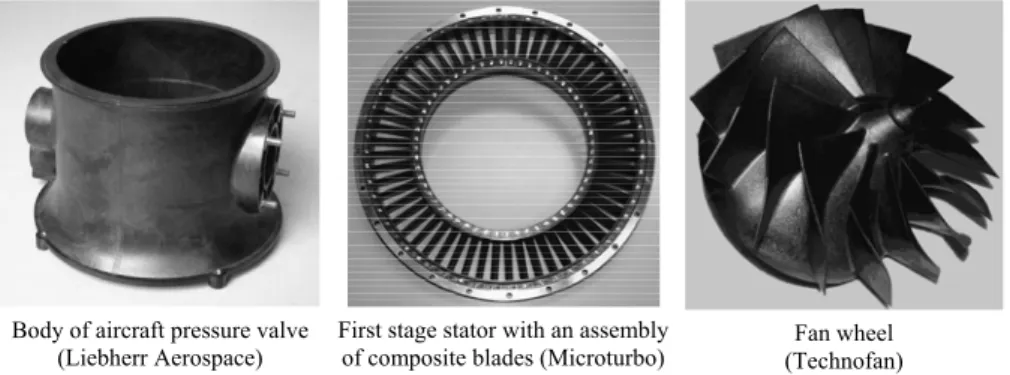
The industrial aspect is aimed to develop, to carry out and to validate composite parts (Figure 1), a body of aircraft pressure valve, a fan wheel and a first stage stator for a gas turbine based on the industrial competences of the Midi-Pyrenees.
Body of aircraft pressure valve (Liebherr Aerospace)
First stage stator with an assembly
of composite blades (Microturbo) (Technofan)Fan wheel
Figure 1. Industrial goals (in Ultem 2300)
The objective of the research task consists in characterizing the coupling between the design and the manufacture of semi-structural composite parts injected with short fibres, in order to carry out a stress analysis representative of heterogeneity of the injected item. It is well-known that the reality of the composite material only exists in the achieved part and strongly depends on the manufacturing process. However there is no optimization method of the process, no design tool at the disposal of the industrial engineering and design departments allowing to account for this reality. It represents an impediment of the economic interest of the composite solution regarding the traditional metal solutions.
For the injected short fibre composites, the knowledge of the local orientation of the fibres or the presence of welded joints implied by the filling mode of the moulds or the voids is the main feature. Indeed to design the mould, the plastic moulder has to know the distributions of the fibres orientation in order to control the shrinkages while cooling. In the same way, before the design of the mould, the mechanical engineer has also to get the fibres orientation to realise a mechanical design faithful to the heterogeneity of the material. Thus, the orientation mechanisms during the filling are the common denominator between the plastic moulder and the mechanical engineer's works.
The research group thus intends to deal with these whole problems in the experimental and numerical aspects, from the manufacturing process to the structural analysis and the final control of the defects within the injected parts. At the sides of the industrial firms, the academic partners are the research team PRO²COM of the LGMT and the CROMeP of the Engineering School of the Mines in Albi-Carmaux (EMAC). Three PhD. works are linked to there. This paper more particularly features the assessment about research team PRO²COM of the LGMT (PhD.1 in progress by E. Haramburu, jointly supervised with MICROTURBO
company).
A main part of this work to do within the research strategy (Figure 2) is the interfacing of the industrial computational tools of fibres orientation and mechanical response of structures. The mathematical representation of the fibres orientation follows Advani's method (Advani and Tucker, 87). It is integrated within the calculation methods of the mechanical properties, based on homogenization techniques.
Figure 2. Research strategy
As far as the application is concerned, this interface allows to gather the results of a numerical simulation of injection with fibre orientation data (components of the Advani's tensor), one finite element after the other and in the thickness of the piece. An estimation of the homogenized mechanical properties is carried out locally thanks to the Mori and Tanaka's method. The interface then builds the numerical pattern in relation to a code by associating the calculated local properties with the finite elements and a chosen mesh (from a same CAD pattern for the two analysis types).
1 This work features interactions with two other PhD. in progress (M. Wesselmann and G. Saint-Martin) supervised by CROMeP and LIEBHERR and TECHNOFAN firms.
Interface and homogenisation calculation Computational structure mechanics Design of the industrial part: fibre orientation Mechanical tests (specimens and structures) Numerical representation of flow Experimental reference:
SEM observations and image processing
The results corresponding to the various stages carried out by the interface program are at the disposal of the design department engineer in order to check its relevance. The quantitative validation of this approach known as "wholly numerical", in particular thanks to some tests on industrial structures, is currently done.
2. Elastic properties estimation method
The heterogeneous nature of the injected short fibre composites represents an application field well adapted to the micromechanical modelling from homogenization techniques. Indeed, these methods consist in determining the elastic properties of an equivalent homogeneous material from the properties of the various components. Moreover, they can be extended to the nonlinear behaviour and damage problems (Collombet et al., 97), (Dunn and Ledbetter, 97), (Wang and Weng, 92).
The homogenisation is carried out on average of an elementary representative volume (ERV) of the material with the condition of choosing an ellipsoidal geometrical representation of heterogeneities. The ERV is the volume of the material containing all the heterogeneities (microscopic scale) influencing the mechanical response (macroscopic scale). In a classical way, a first stage called "the representation stage" requires to choose the various heterogeneities types and their geometrical dimensions associated with their ellipsoidal representation. This choice often knows a numerical fitting with the experiment on elementary specimens and controlled conditions of injection.
The stage of "localization" consists in defining average constitutive laws between the micro and macro-scale (Hill, 63). Thanks to strain- and stress-concentration tensors A and B as ratios between the average heterogeneity strain (or stress) and the corresponding average in the composite, stiffness and compliance tensors C and S of composite are given by:
(
)
∑
(
)
∑
= = ⋅ − + = ⋅ − + = N 1 i i 0 i i 0 N 1 i i 0 i i 0 f C C A or S S f S S B C C [1]where superscript i indicates quantities associated with the N heterogeneities of the ERV, and superscript 0 denotes a matrix quantity. Symbol f represents the volume fraction for matrix or heterogeneity phases.
Equation [1] gives dual generic expressions for stiffness and compliance tensors in terms of strain- and stress-concentration tensor A and B. Then, the different micromechanical approaches in the literature provide different ways to approximate A or B.
2.1. Eshelby's modelling
Eshelby (Eshelby, 57 and 61) calculates the disturbance of the strain field in the ERV because of the presence of a heterogeneity of given elastic properties (principle of equivalent inclusion). Eshelby obtains the strain-concentration tensor (in the principal local directions of heterogeneity i) such as:
(
)
[
i 0 i 0]
1i
E I E S C C
A = + ⋅ ⋅ − −
where symbol I represents the fourth-order unit tensor and Ei denotes the Eshelby's
tensor in accordance to the shape of the ellipsoidal heterogeneity by its aspect ratio r=l/d (with l and d, respectively the length and the diameter) and of the elastic properties of the isotropic matrix by the Poisson's ratio (Mura, 82).
Moreover, if we consider an orientation of the heterogeneity i in the global directions of the ERV, one obtains (Pettermann et al., 97):
( )
[
(
)
]
( )
1 i i 1 0 i 0 i i i i E T , I E S C C T , A − − φ θ ⋅ − ⋅ ⋅ + ⋅ φ θ =where T
( )
θi,φi is the transformation tensor for fourth-order tensors in terms of Eulerangles θi and φi which performs the rotation from the local system of heterogeneity i
RLOC to the global ERV system RERV (Figure 3).
Figure 3. Local directions RLOC in the heterogeneity i in the global directions RERV
However, Eshelby's modelling represents the elementary situation of an isolated heterogeneity. It does not take into account the interactions between the ERV phases. From the model given by Eshelby, Mori and Tanaka have determined a disturbance on average in the macroscopic fields due to the each heterogeneity presence in the ERV.
2.2. Mori & Tanaka's method
The aim of Mori & Tanaka's method (Mori and Tanaka, 73) is to take into account the influence of the local interactions between the phases on the stress and strain fields of the ERV. According to Benveniste formulation (Benveniste, 87), the obtained strain-concentration tensor is as follows:
1 N 1 j j E j 0 i E i MT A f I f A A − = + =
∑
[2]From [1] and [2] the ERV equivalent stiffness is given by:
(
)
∑
∑
= − = + ⋅ ⋅ − + = N 1 i 1 N 1 j j E j 0 i E 0 i i 0 ERV MT C f C C A f I f A C [3]3. Coupling of the Advani's tensor and Mori and Tanaka's method
A mathematical representation of fibres orientation distribution (FOD) in injected composite material with a symmetric rank 2 tensor is proposed by Advani (Advani and Tucker, 87). As much as this quantity is commonly used to provide fibre orientation results from simulation or measurements, Advani's tensor does not allow a direct estimation of the overall set of elastic properties.
The use of the Advani's tensor in an estimation of the elastic properties of an equivalent homogeneous material has to be performed in accordance to the geometrical meaning of the components aij. In particular, the components a11, a22 and
a33 show the probability of presence of a fibres population in the primary global
basis associated with the given Advani's tensor. The off axis components (a12, a13
and a23) are essential to the three-dimensional geometrical representation of FOD but
it is difficult to underline the physical reality of their contributions.
Thus, the eigendirections of the Advani's tensor corresponding to ERV vectors basis represent always a fair situation in order to use FOD into Mori & Tanaka's method. By meaning of the corresponding eigenvalues αi as probability of presence
of three heterogeneities, the fibres volume fraction f in the ERV is spread in the eigendirections with αif.. The relation [3] becomes:
(
)
∑
∑
= − = α + ⋅ ⋅ − α + = 3 1 i 1 3 1 j j E j 0 i E 0 i i 0 ERV MT C f C C A f I f A C [4]In the above relation, we note that Eshelby's strain-concentration tensors i E
A depends on the transformation tensor in terms of Euler angles which performs the rotation from local system of each heterogeneity in each eigendirection to principal basis of Advani's tensor.
The elastic properties thus calculated are expressed in the principal directions of the Advani's tensor. Finally, the shift from the principal directions to the primary directions of Advani's tensor is performed thanks to the transformation tensor built with the normalised eigenvectors.
To sum up, the probability of presence of fibres in a given direction is represented by the diagonal Advani's tensor. Its principal directions define the great axis of the three heterogeneities for the corresponding fibres groups. They represent the directions of the local axis of the heterogeneities whose respective fibre contents are a weighting of the total fibre content by the eigenvalues of the Advani's tensor. Mori and Tanaka's estimation of the stiffness matrix of the equivalent homogeneous material is carried out in these axes. The last stage consists in coming back to the primary basis.
4. Interfacing the simulation tools
Calculating the elastic properties from the orientation tensors is used to interface the tools of the injection simulation through the orientation prediction and the computer codes of structure.
4.1. Interfacing strategy
For the design of a part, the engineer has to fulfil the feasibility and mechanical behaviour requirements. FOD is the bridge between results of the injection condition simulation and a stress analysis, starting from determining the homogeneous mechanical properties. This tool has to be usable by the design department. For that the designer must have means of graphically representing the intermediate results for a non stop analysis from the process to the structure design.
MTD (Mori-Tanaka-DOS) is the generic name of the program allowing the processing of orientation measures coming from the analysis of MEB images or from a simulation thanks to Moldflow® software for example.
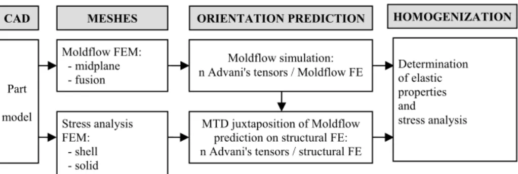
In this way, the series of operations leading to a stress analysis starts with a CAD model of the part (Figure 4). The part is then meshed and imported in Moldflow® injection simulation software used in this study. According to the adjustments of the specified injection parameters (pressure, temperature, gate(s) localization and so on), the calculation of the orientation prediction is made. As output data, the orientation results are given in the form of one or several Advani's tensors per finite element (several Advani's tensors for the given finite element represent the FOD through the thickness).
Starting from the orientation data, the calculation and the localization of the distributions of homogeneous elastic properties are performed along the injected parts. A first possibility is to calculate mechanical characteristics to the finite
elements defined for a Moldflow® simulation. The cell used for the injection model, can be use for a stress analysis. Apart from the Moldflow® meshing, the designer can juxtapose a mesh devoted to the stress analysis (with other types of finite elements, thinness, and so on). It should be emphasized that this assignment of properties is done by means of a proximity criterion. This criterion gets a sense only if the two meshes (Moldflow® and stress analysis) have been created from the same CAD model of the studied part and with some obvious conditions of common sense.
Figure 4. Interfacing strategy and operation sequence
4.2. MTD interface patterns
Interface MTD is a program written in FORTRAN 77 allowing a wide use under MS-DOS and UNIX with various blocks of routines representing more than 10000 lines of code. The user interface allows the acquisition of input data via a command file with a MTD specific syntax. The designer has some "user" information currently operating at his disposal such as the data card reports or warnings and errors during MTD execution. A graphic interface called XMTD can be the user's assistant for the edition of the command files, the executions of calculations and the visualization of the intermediate results provided by MTD.
5. Numerical results
Several illustrations of the various stages of the calculation sequence are presented for the three industrial parts.
5.1. The orientation prediction
The fibres orientation data are obtained at the end of filling simulation of the volume of the part (performed by Moldflow®) with the injection parameters defined thanks to the moulder. The study is limited to the mere filling phase. The runners, the global cycle of injection including the packing and cooling times have not been
Moldflow FEM: - midplane - fusion Stress analysis FEM: - shell - solid MESHES Moldflow simulation: n Advani's tensors / Moldflow FE
MTD juxtaposition of Moldflow prediction on structural FE: n Advani's tensors / structural FE
ORIENTATION PREDICTION Part model CAD HOMOGENIZATION Determination of elastic properties and stress analysis
modelled. These reductions are justified because only the FOD are required. In this case, we suppose that only the filling phase has an effect on the FOD (Figure 5).
Body valve - Scale 1/6 Stator blade - Scale 2/3 Fan wheel - Scale 1/6
Figure 5. Filling of industrial parts at 0.5 second (Moldflow® software)
5.2. Computation and assignment of elastic properties
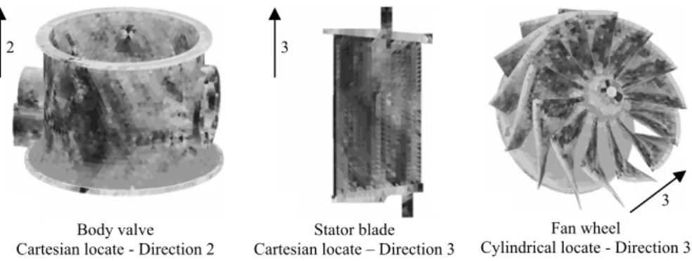
The orientation tensors are the input data of calculation, in each finite element (ERV), of the elastic properties for their use in a stress analysis via the MTD interface. The visualization of the properties is not possible with the commercial computer codes such as for example the codes used by the project partners (Samcef®, Ansys®, I-deas® and Nastran®). Visualization options can be activated by MTD interface for real noting the distributions of some Young's moduli of the composite parts (Figure 6). Figure 6 shows for example with grey levels the distribution of the Young's modulus in the direction of the paddle height of the Microturbo stator blade.
Body valve Cartesian locate - Direction 2
Stator blade Cartesian locate – Direction 3
Fan wheel Cylindrical locate - Direction 3
Figure 6. Distribution of the mechanical characteristics (Young's moduli in Pa)
These computations have been done by giving the following values to the characteristics of the matrix and the short fibres (Ultem®2300: GE Plastics):
3 2
- Ultem®1000 matrix: E = 3.2 Gpa and ν = 0.38
- Glass fibres E: E = 70 GPa, ν = 0.20, r = 15 and f = 17.5%
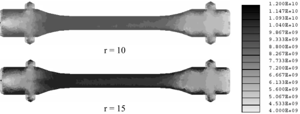
The aspect ratio r equal to 15 has been obtained after a numerical fitting by MTD thanks to simple standard traction specimens (Figure 6). This result recovers an experimental characterisation of the length distribution of fibres carried out by C. Levaillant's research team and Liebherr Aerospace. In more detailed way, the injection and filling conditions impose a single direction of the fibres along the great axis of the specimen. The experimental value of the Young's modulus in this direction is of 9.8 GPa. Figure 6 shows a strong sensitivity of the Young's modulus versus the aspect ratio. Indeed, a corresponding value for r = 10 is about 9 GPa. In this situation, it is obvious to get the accurate aspect ratio value thanks to homogenization.
r = 10
r = 15
Figure 7. MTD distribution of the Young's modulus (in Pa) values after injection in
the main axis of the specimen
5.3 Stress analysis
The stiffness matrices calculated on each finite element of the Moldflow® mesh can give birth to the following alternative. They can be used for the export of elastic moduli on the same elements and finally for the edition of a data file for a computer code containing the coordinates of the nodes, connections of the finite elements and the elastic moduli of the composite (what implies in our example to re-use the triangles of the Moldflow® model). The stiffness values can be assigned on geometrical points thus making possible to associate elastic moduli with the finite elements of another mesh type which would come to be superimposed instead of that of the Moldflow® model. In this case, MTD writes a data file for a computer code containing only the characteristics of the materials assigned to each finite element of the mesh chosen for the stress analysis.
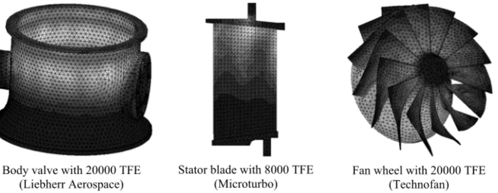
Finally, the output data of MTD interface allow to start a stress analysis for any model. The nodes, the finite elements and the properties of materials being defined, it remains then to provide the modelling elements relating to the boundary conditions for example to end mechanical calculations (Figure 8). With the confidential industrial specifications of the modelling stages, a numerical simulation of the stator blade with quadratic tetrahedral finite elements is performed, body valve and fan wheel as well.
Body valve with 20000 TFE (Liebherr Aerospace)
Stator blade with 8000 TFE
(Microturbo) Fan wheel with 20000 TFE (Technofan)
Figure 8. Von Mises stress map for the three parts under their mechanical operation
by Samcef software after the backing of the Moldflow® orientation predictions
7. Conclusion
The main problem of the short fibres composite structures is the lack of information concerning the heterogeneity in the composite parts. The heterogeneous nature depends on both the process and the design phase. It is an impediment of the development of this solution in industry for a low cost. The cost reduction of composite parts depends on the development of an advanced numerical tool capable to loop from the manufacturing conditions to the mechanical response of a part. The MTD interface is right now used by the industrial partners with their own codes of structure. This interface allows the designer to take into account the influence of the injection process on the distribution of the mechanical properties. The experimental validation is in progress thanks to industrial partners on several scales, starting from the specimens to the industrial parts in service conditions.
Acknowledgements
The authors would like to thank Claude Rossignol and Matthias Wesselmann (Liebherr Aerospace), Olivier Darnis and Gilles Saint-Martin (Technofan) for their helpful technical
collaboration. This work was done with the financial support of the Midi-Pyrenees Regional Council and the French Agency of Technical Research (ANRT).
8. Bibliography
Advani S.G., Tucker III C.L., "The Use of Tensors to Describe and Predict Fiber Orientation in Short Fiber Composites", J. of rheology, vol.31, 1987, p. 751.
Benveniste Y., "A new approach to the application of Mori-Tanaka’s theory in composite materials", Mechanics Materials, vol. 6, 1987, p. 147-157.
Collombet F., Bonnan S., Hereil P.L., "A mesomechanical modelling of porous aluminium under dynamic loading: comparison experiment - calculation", International conference
on mechanical and physical behaviour of materials under dynamic loading, Eurodymat
97, Toledo (Spain), 22-26 September 1997, Journal de Physique IV, Colloque C3, Les Editions de Physique, 1997, p. 643-648.
Dunn M.L., Ledbetter H., "Elastic-Plastic behavior of textured short-fiber composites", Acta
Metallurgica, Vol. 45, n°8, 1997, p. 3327-3340.
Eshelby J.D., "The determination of elastic field of an ellipsoidal inclusion and related problems", Proceedings of the Royal Society, London, vol. A241, 1957, p. 376-396. Eshelby J.D., "Elastic inclusions and inhomogeneities", Sneddon IN, Hill R. editors, Progress
in solid Mechanics, vol.2, 1961, p. 89-140.
Haramburu E., "Etude des couplages entre la conception et la fabrication de pièces composites semi-structurales injectées avec fibres courtes, en vue de l'obtention de propriétés mécaniques optimales", Rapport d'activités de 1ère Année de Thèse, LGMT/PRO²COM, 2001.
Hill R., "Elastic properties of reinforced solids: Some theoretical principles", J. Mech. Phys.
Solids, vol. 11, 1963, p. 357-372.
Mori T., Tanaka K., "Average stress in matrix and average elastic energy of materials with misfitting inclusions", Acta Metallurgica, vol. 21, 1973, p. 571-574.
Mura T., "Micromechanics of defects in solids", Martinus Nijhoff Editor, The Hague, 1982. Pettermann H.E., Böhm H.J., Rammerstorfer F.G., "Some direction-dependent properties of
matrix-inclusion type composites with given reinforcement orientation distributions",
Composites Part B: engineering, vol. 28B, 1997, p. 253-265.
Wang, Weng, "The influence of inclusion shape on the overall viscoelastic behavior of composites", ASME, Vol. 59, 1992, p. 510-518.