P/GM/N/07
Page 749
CLAYS IN NATURAL & ENGINEERED BARRIERS FOR RADIOACTIVE WASTE CONFINEMENT 4TH INTERNATIONAL MEETING – MARCH 2010 – NANTES, FRANCE
A SUBCRITICAL DAMAGE MODEL FOR CLAY
AS A TWO-SCALE MATERIAL
B. François, C. Dascalu
Laboratoire Sols Solides Structures – Risques, UJF, INPG, CNRS UMR 5521, Domaine Universitaire, BP 53, 38041 Grenoble cedex 9, France ([email protected], [email protected])
A time-dependent damage law for Clay has been built starting from considerations at the micro-scale where non-planar subcritical growth of micro-cracks is assumed (François and Dascalu, 2010). The passage from the micro-scale to the macro-scale is done through an asymptotic homogenization approach including the size of the microscopic cell as a material parameter. The stress-strain relationship is controlled by homogenized coefficient and a subcritical damage law defines the evolution of damage. The developed model enables to reproduce not only the classical short-term stress-strain response of materials (in tension and compression) but also the long-term behavior encountering relaxation and creep effects.
We consider the medium as two-dimensional isotropic elastic containing a locally periodic distribution of micro-cracks. Each crack is straight with a length 2a and an orientation of angle θ with respect to the abscissa of the referential system considered at the macro-scale. The damage variable d is defined as the ration between the crack length 2a and the size of the periodicity cell ε (Figure 1). On the crack faces, traction free opening or frictionless contact conditions are assumed.
The asymptotic homogenization is used to deduce the macroscopic (homogenized) behaviour starting from the response of the periodic structure (at the micro-scale) (Leguillon and Sanchez-Palencia, 1982; Dascalu et al., 2008). The unit cell is rescaled by the parameterε(Figure 1b).
The evolution of the crack length 2a (i.e. the propagation of the crack) is evaluated through a subcritical criterion adapted from the Charles’ law (Charles, 1958):
where K0, v0and n are material parameters. K*
Iis the stress intensity factor for the tensile mode of rupture
(Mode I). The star indicates that the stress intensity factor is related to the kinked crack (Figure 2) K*
Idepends on the stress (or strain) conditions, the internal lengthεand the geometry of the micro-cracks.
The determination of this stress intensity factor is made through the computation of path-independent J-, L- and M- integrals (Kienzler and Herrmann, 2000) for straight trajectory of micro-cracks and from the Figure 1: (a) Fissured medium with locally periodic microstructure. (b) The fissured cell. 2a: length of the micro-crack, ε: distance between two micro-cracks (internal length), θ: orientation of the micro-crack with respect to this (×1 ; ×2) system.
da dt v K K1 * n = 0 0
P/GM/N/07
Page 750 CLAYS IN NATURAL & ENGINEERED BARRIERS FOR RADIOACTIVE WASTE CONFINEMENT 4TH INTERNATIONAL MEETING – MARCH 2010 – NANTES, FRANCE
polynoms of Leblond (1999) for the kinked cracks. The crack is assumed to propagate in the direction that maximizes the energy release rate. This criterion produces a kinking angle between the existing crack and the incremental propagated crack (Figure 2). At each step of
calculation, an equivalent crack is determined by means of geometrical relationships, by joining the tips of the real branched crack.
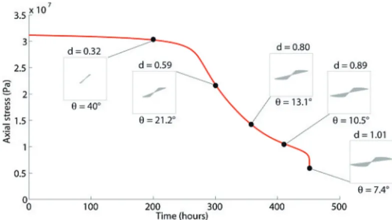
Figure 3 shows numerical simulations of a relaxation test in tension. Under a constant strain level, the subcritical micro-crack growth produces a progressive decrease of the rigidity as long as the damage state increases. As a consequence, the axial stress is gradually relaxing upon failure. At such an ultimate state, the microcracks coalesce and the rigidity tends to zero. The non-planar growth of micro-cracks produces a rotation of the equivalent cracks to be oriented perpendicularly to the loading. This example focuses on a tension test. However, material damage is also increasing under macroscopically compression field, producing wing-shaped crack growth.
References:
Charles, R., 1958. Dynamic fatigue of glass. J. Appl. Phys. 29, 1657-1662.
Dascalu, C., Bilbie, G., Agiaso, 2008. Damage and size effect in elastic solids: A homogenization approach. Int. J. Solid Struct. 45, 409-430.
François, B., Dascalu, C. (2010). A two-scale time-dependent damage model based on non-planar growth of micro-cracks. (Submitted).
Kienzler, R., Herrmann, G., 2000. Mechanics in material space with applications to defect and fracture mechanics. Springer-Verlag, Berlin Heidelberg.
Leblond, J.B., 1999. Crack paths in three-dimensional elastic solids. I: two-term expansion of the stress intensity factors - application to crack path stability in hydraulic fracturing. Int. J. Solids Struct. 36, 79-103.
Leguillon, D., Sanchez-Palencia, E., 1982. On the behavior of a cracked elastic body with (or without) friction. J. Mech. Theor. Appl. 1, 195-209.
Figure 3: Exemple of a relaxation test in tension. Evolution of the axial stress with time.
Figure 2: Kinked crack (out-of-plane crack growth). φmax is the angle between the crack plane and the crack extension. Dashed line is the equivalent crack.