ASSESSMENT OF RANKINE WASTE HEAT RECOVERY POTENTIAL
ON HEAVY DUTY TRUCKS USING DIRECT CONDENSATION
Francesco Galuppo1,2,3, Vincent Lemort2*, Madiha Nadri3, Pascal Dufour3, Thomas Reiche1
1Volvo Group, Powertrain Strategic Development, 1 Avenue Henri Germain, 69800, Saint Priest,
France (e-mail: francesco.galuppo@volvo.com, thomas.reiche@volvo.com)
2Thermodynamics Laboratory, University of Liège, Campus du Sart Tilman, B49, B-4000 Liège,
Belgium (e-mail: vincent.lemort@ulg.ac.be)
3Univ Lyon, Université Claude Bernard Lyon 1, CNRS, LAGEPP UMR 5007, 43 boulevard du 11
novembre 1918, F-69100, Villeurbanne, France. (e-mail: madiha.nadri-wolf@univ-lyon1.fr, pascal.dufour@univ-lyon1.fr)
* Corresponding Author
ABSTRACT
Upcoming regulations on CO2 emissions for heavy duty trucks and increasing fuel prices lead the truck manufacturers to adopt new solutions to reduce fuel consumption. The Organic Rankine cycle (ORC) is a promising technology that can contribute to achieve such a goal. Rankine cycle waste heat recovery on heavy duty trucks has been studied over the past decade by focusing on fluid selection, modeling, control and components development. Cost, integration and up-time are also considered important aspects for a future series production.
The objective of this study is to evaluate the performance of a Rankine system by simulating road cycles on a complete truck simulation environment (Exhaust after treatment system, as well as cooling system and the energy management of the mild-hybrid driveline are modeled). The Rankine system uses exhaust gas flow as heat source, an air cooled condenser and a volumetric expansion machine. Two working fluids are selected for this study; ethanol and cyclopentane.
The dynamic equations used for Rankine component modeling are provided and a particular attention is dedicated to the condenser and fan models. In order to ensure complete condensation of the working fluid, two controllers are implemented to track a set-point on subcooling at the condenser outlet by acting on the fan speed and the condensing pressure. Afterwards a comparative study is carried out to assess the relative potential of the two fluids using direct condensation.
1. INTRODUCTION
The European commission proposed in 2018 (InternationalCouncilOnCleanTransportation (2018)) a reg-ulation on CO2 emission targets for heavy duty transport. This regreg-ulation foresees a reduction of 15% of CO2 emissions by 2025 and 30% by 2030 compared to the sold fleet with respect to a benchmark from 2019.
In order to meet the new limits of emission, Original Equipment Manufacturers (OEMs) are orienting re-search and investments to increase efficiency and thus to reduce fuel consumption. Roughly 40% of the fuel energy is transformed to heat and roughly 30% of the heat is released into the exhaust gas tailpipe. Several research topics of the last two decades have addressed the re-utilization of the waste heat (Xu et al. (2019)).
Different technology have been studied in the last decades concerning waste heat recovery (WHR) in the heavy duty vehicles. Thermo-electrical generators (TEG) take advantage of a temperature difference to
produce electrical energy making use of the Seebeck effect. As highlighted in the works of Atouei et al. (2017) the heat to electricity efficiency of TEG is only about 2%.
Turbo compound recovers part of the residual heat of the tailpipe exhaust gas, improving the overall fuel efficiency. This technology consists in a gas turbine that is installed in series in the exhaust gas tailpipe and directly connected to the engine crankshaft; the utilization of the mechanical turbo compounding leads to advantages mainly related to packaging. Mechanical turbo-compounding can require the use of a variable or constant speed transmission between the turbocharger and the engine (Varnier (2012)). The turbine adds power to the crankshaft, but in the same time it increases the engine exhaust backpressure. However the turbine power delivered increases with the engine speed and load, therefore it is particularly effective with highly rated or high speed engines and not in truck cruise conditions.
A more valuable alternative is the use of an electrical turbocompound system; a high speed generator is connected to the turbine and the energy is then injected in the crankshaft through a motor-generator. The advantage of this solution is the lack of any direct connection to the engine and therefore the possibility to control the turbine speed to maximize power and increase efficiency. On the other hand, this solution requires the installation of an electrical energy storage device and an electric machine.
In the context of WHR systems for trucks, thermodynamic cycles have also been studied. Recently, Güven et al. (2019) proposed a Stirling engine recovering exhaust gas on a Euro VI heavy duty truck. The authors compared the Stirling engine with other bottoming cycles and claimed a fuel consumption reduction of 1% as a result of road cycle simulations.
A meaningful comparison by means of steady state simulations of the main waste heat recovery solu-tions to adopt in internal combustion engine (ICE) vehicle was developed by Legros et al. (2014). They highlighted the advantages and drawbacks of different technologies (turbo-compound, thermoelectric generators, thermoacoustic generators, Stirling engine and Rankine cycle) considering efficiency, cost, packaging, maturity and weight to power ratio. Thermoelectricity shows very limited potential on power production, while Rankine cycle produces slightly less power than turbo-compound but it has a higher utilization. On the other hand, Rankine cycle needs to be cooled, therefore thermal power has to be re-jected from the condenser.
Heat rejection is a main issue for the truck integration. Battista et al. (2018) presented an ORC that uses as condenser an aluminum radiator installed in the front face of the truck; condensation is ensured by the intake air in the front face and in the high load phases fan is engaged. Yang et al. (2019) proposed the same architecture; they highlighted that control and optimization of the system, involving exhaust gas by-pass, condensation pressure and engine fan are necessary to ensure complete condensation and achieve the best overall performance. Grelet et al. (2016) presented a similar architecture, highlighting the fact that the higher load in the cooling module can lead to the limitation of the heat recovery and by consequence of the produced useful work. In the FP7 NoWaste project (Bettoja et al. (2016)), a low tem-perature radiator (LTR) is placed between the charge air cooler (CAC) and the high temtem-perature radiator (HTR) and an additional water loop with a dedicated pump is used as heat sink. The author fixed the heat rejection from the condenser at 35kW, in order to contain the fan activation in the real truck and the correspondent power demand that could be higher than the benefit of the Rankine.
The focus of this work is to present an independent solution for the condensation; the aluminum con-denser is placed behind the cab, therefore no natural air intake is ensured and the heat sink is represented by air flow provided by an electrical driven fan. A 1D model is presented to evaluate the operating points of the system composed by the fan and the condenser and road cycle simulation results are then presented to compare the overall performance of the Rankine using ethanol and cyclopentane based mix-ture as working fluid.
2. MODELING
Heat rejection from the condenser in an ORC can be a major issue for truck integration. The complete condensation of the working fluid has to be ensured by a heat sink, that cools down the working fluid to
a temperature set point at the outlet of the condenser. However, the energy demand to provide the cold fluid should be as small as possible to not impact in a negative way the efficiency and the net power of the thermodynamic cycle.
Basically three main architectures can be envisaged to realize the transformation and ensure subcooling at the outlet of the condenser:
• The use of high temperature (HT) radiator in the front face of the truck that is directly cooled and ensures the cooling of the engine as well as the Rankine condenser
• The use of an additional low temperature (LT) radiator in the front phase of the truck. In this case, the radiator can be used to cool down directly the working fluid (direct condensation) or water belonging to a separated loop that has the role of heat sink of the Rankine (indirect condensation) • A direct condensation where the heat sink is represented by air flow provided by an electrical
driven fan and the condenser is placed behind the cab (no air intake flow).
Yang et al. (2018) investigated the integration in the truck of a Rankine based WHR system using the engine cooling system as a heat sink; they placed an additional low temperature radiator and performed simulations by means of a 0D-1D model. Results show a big impact of the Rankine on the cooling system and a thermo-management strategy is necessary to reduce impacts and reach better performance. The architecture that is here proposed (Fig.1) recovers the energy of the exhaust gas. The working fluid pressure is increased in the pump, afterwards it receives one part of the exhaust gas energy and it is evaporated and superheated. A volumetric expansion machine is used to expand the working fluid and produce mechanical power and a condenser ensures the complete condensation of the working fluid. In this architecture an independent solution to cool the Rankine is presented, in order to avoid any impact on the engine cooling system. The condensation is ensured by air flow that is provided by an electrical driven fan (third cooling architecture among the possibilities above mentioned). However, saturation of the fan actuator can occur in very high thermal load phases. In this case, the first action to facilitate the condensation is to increase the condensation pressure and in the most extreme cases exhaust by-pass can be opened.
Figure 1: Working fluid in the Rankine system (green) and exhaust gas (red) paths
The air flow is then entirely provided by the electrical driven fan. The fan provides the necessary air flow rate to ensure the subcooling and considering the fan pressure losses of the condenser it consumes electrical power to deliver the air flow rate.
This section presents a model for the condenser, the electrical driven fan and the implementation of the system in the truck to run road cycle transient simulations. The simulation tool is Simulink (developed by MathWorks).
2.1 Condenser modeling
The selected condenser is a corrugated louver aluminum radiator with rectangular channels, tube and fin type (Chang and Wang (1996)). The condenser model is obtained using a 1D finite volume (FV) discretization. Energy and mass balance conservation equations are applied to the gas side, fluid side and separation wall. Thermal losses to the environment are neglected as well as the pressure losses fluid side, except for the pressure losses of the recuperator, in order to take into account the presence of this additional component. Mass balance: Vi ∂ ρi ∂t = ˙min,i− ˙mout,i (1) Power balance: ∂(mh)i ∂t = ˙Qi+ ( ˙minhin− ˙mout),i, (2)
where i is the i-th control volume, h is the specific enthalpy (J/kg), ˙Q is the thermal power transferred to the control volume or removed from the control volume, in is the index for the volume inlet, out is the index for the volume outlet, ˙m is the mass flow rate and ρ is the fluid density.
In order to compute correctly the thermal power exchanged between the fluid and the wall, and between the wall and air flow, a geometrical analysis of the condenser is necessary. Geometrical data can be retrieved by calculations, once the fluid side and air side exchange areas are set (these data are available from the supplier). Considering the fluid side, the fluid flows in channels that are obtained in the tubes; according to Kandlikar (2002) channels of the size that is between 0.2 and 3 mm are considered as mini-channels. Here the mini channels have a rectangular section. Thanks to this data and knowing the fluid side heat exchange area, it is possible to compute the fluid flow area and the number of mini channels per tube. These data are particularly useful for the definition of the flow regime and calculation of the heat transfer coefficients in single phase and two-phase. The following correlations have been used to compute the fluid side heat transfer coefficient:
• Dittus-Boelter correlation for single phase flow
Nusp= 0.023Re0.8DhPr
0.3 (3)
where ReDh is the Reynolds number calculated in the flow area fluid side and Pr is the Prandtl
number.
• The Shah correlation for two-phase flow (Shah (1979)) Nu= Nusp[(1 − x)0.8+
3.8x0.76(1 − x)0.04
P0.38red ] (4)
where x is the quality of vapor and Pred is the reduced pressure defined as the ratio of the actual
fluid pressure and the critical pressure of the fluid (Shah (1979)).
Regarding the air side, several other studies have been conducted in the last decades (HieChan and GilWoong (2011), Chang and Wang (1996), ElHajal et al. (2003)). For this work, the correlation pro-posed by HieChan and GilWoong (2011) has been chosen because of the wide combination of different geometries of louvers and fins that have been investigated. The empirical correlations allow to compute the Colburn number j and the friction factor f (Fig. 2.a ), that are useful to find respectively the heat trans-fer coefficient on air side has(Fig. 2.b) and the the pressure drop of the air through the condenser.
(a) f - j (b) h - ΔP
Figure 2: (a) Friction factor and Colburn number as a function of the Reynolds number calculated in the minimum flow section (louver section). (b) Heat transfer coefficient and pressure drop as a function of the Reynolds number calculated in the minimum flow section (louver section)
j= ηhPr
2/3
ρuccp
(5) where η is the fin efficiency, cpis the specific heat of the air and ucis the velocity of the air at the minimum
free section. The heat transfer coefficient and the air pressure drop as a function of the Reynolds number are shown in Fig. 2.b.
Fig.2.a and 2.b show coherent results according to literature in terms of absolute values and variation with the Reynolds number.
2.2 Fan modeling
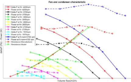
Fan suppliers provide the fan curve, which expresses the static pressure (ΔP) variation through the fan as a function of the volumetric flow rate (m3/h) at nominal speed. Curves at other speeds can be found thanks to the Fan Laws (Kanefsky et al. (1998)). Plotting in the same graph the fan curves at different fan speed and the pressure drop curve characteristic of the condenser , it is possible to identify the intersections, hence the operating points of the system. The condenser model predicts the condenser pressure drop from data supplier with a relative error of 1% in the range of interest of volume flow rate (Fig. 3).
2.3 Integration in the vehicle environment
The above mentioned system characterized by the fan and the condenser is integrated in the global sim-ulation platform already presented in Galuppo et al. (2019). In order to perform transient road cycle simulations, control of the main actuators of the Rankine is needed:
• The pump speed is manipulated in order to obtain proper conditions of the working fluid at the inlet of the expander (Galuppo et al. (2018),Galuppo et al. (2019)).
• The expander speed is manipulated in order to optimize the pressure ratio and reach the best Rank-ine power output.
• The fan speed and the condensation pressure are manipulated in order to ensure the proper physical condition of the working fluid at the outlet of the condenser.
In the proposed architecture, the latter is the main critical problem to be addressed; in particular the subcooling SCout,cond, defined in Eq. 6, is the variable to be kept always positive in order to reach the
complete liquid state of the working fluid at the inlet of the pump.
Figure 3: Fan static pressures and power demands at different fan speeds and condenser pressure drops. The condenser pressure drop is predicted (green resistance line) with an error of 1% with respect to the supplier data (red resistance line)
where Tsat(Pcond) is the saturation temperature of the working fluid at the pressure Pcondand Tout,condis
the temperature of the working fluid at the outlet of the condenser.
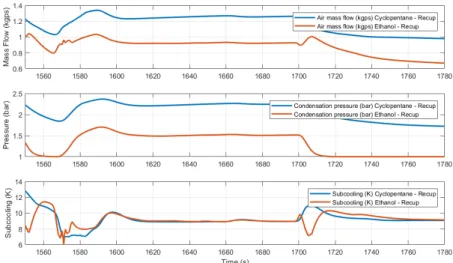
A PID controller, tuned using the half rule of Skogestad (2003), with anti-wind up gain is implemented to track the subcooling set point. When the subcooling cannot be ensured using the only fan speed actu-ator (because of the limitation of the delivrable flow rate), the condensation pressure is then increased; in detail, the condensation pressure is increased by a value of 0.1 bar as soon as the subcooling is lower than 5K. In fact, the condensation pressure is chosen as an effective variable to control in order to reach the desired subcooling when the fan is at its maximum speed. Increasing the condensation pressure leads to a higher difference between the mean temperature of the working fluid in the condenser and the mean temperature of the air in the condenser. This means that with an increased condensation pressure, a smaller amount of air mass flow rate is needed to complete the condensation of the working fluid. The boiling point of the working fluid, defined as the saturation temperature of the fluid at the atmo-spheric pressure, impacts the amount of air flow rate to be provided by the fan. The working fluids that are considered in this work are ethanol and cyclopentane and their boiling point differs a lot from each other (78°C for ethanol, 49°C for cyclopentane). Consequently, it is possible to foresee that the increase of the condensation pressure occurs more often using cyclopentane, in order to reduce the air mass flow rate to be used in the condenser. Fig. 4 shows that the fan provides more mass flow rate using cyclopen-tane and condensation pressure is higher in the case cyclopencyclopen-tane is used in place of ethanol, therefore higher fan power is required to ensure the subcooling at the outlet of the condenser using cyclopentane. The subcooling set point, 10 K, looks well tracked using cyclopentane as working fluid, on the other hand, using ethanol, the controller looks aggressive. Consequently the subcooling controller can be still optimized using ethanol.
3. ROAD CYCLE SIMULATION RESULTS
The road cycle simulations are performed in a complete vehicle simulation environment. Exhaust after-treatment system (EATS), as well as cooling system of the truck have been modeled and integrated in the vehicle model. The engine that is considered for the actual simulation campaign is a Euro 6, 13 liters, non EGR 480HP.
Simulation results are presented on two different road cycles, LCG (a French road cycle, characterized by a smooth route profile) and FK (German road cycle, characterized by high thermal load in the exhaust
Figure 4: Air mass flow and condensation pressure (higher using cyclopentane) and subcooling control
gas tailpipe, 50 kW average), that have been already investigated in Galuppo et al. (2019). FK road cycle results in a higher thermal power that is possible to transfer to the working fluid and this leads to a higher power output of the Rankine with respect to the LCG road cycle. On the other hand, the high consequent thermal rejection in the FK road cycle results in a higher fan power demand with respect to the LCG.
The benefit of the specific Rankine architecture is evaluated considering the net power (NP), Eq.7, of the overall architecture:
NP= GrossPower − FanPower − PumpPower (7)
The Rankine is simulated using the two above mentioned fluids, with the possibility to add an additional heat exchanger (recuperator) that is used to pre-heat the working fluid stream at the inlet of the evapo-rator thanks to the exceeding energy of the working fluid stream at the outlet of the turbine. This device improves the Rankine cycle efficiency by 22% using cyclopentane (considering that roughly 20-25% of the heat provided to the working fluid is transferred in the recuperator). The effect when using ethanol is much lower because of the modest temperature difference between the two streams in the recuperator and the lower mass flow rate with respect to cyclopentane. Another important effect of the recuperator is to reduce the heat rejection from the condenser; this leads to a reduction of the fan power demand and it allows to keep the condensation pressure lower than that achieved with the architecture without the recuperator. A secondary effect of the use of the recuperator is a slight increase of the mass flow rate of working fluid; this is a direct consequence of the fact that a higher thermal power is transferred to the fluid with respect to the case when the recuperator is not used. Fig. 5 shows the situations previously described as a result in the LCG road cycle.
The Rankine using cyclopentane as working fluid provides the best results in terms of gross power of the expander. However the fan power demand differs a lot between the architecture with and without a recuperator, resulting in a lower power consumption in the case of cyclopentane with a recuperator. Basically, this is the reason why the Rankine using cyclopentane without recuperator is characterized by the lower net power output with respect to the architectures with a recuperator.
Figure 5: Effect of the recuperator using ethanol and cyclopentane in LCG road cycle. The differ-ence of temperature between cold and hot fluid in the recuperator is higher using cyclopentane. The recuperator reduces the thermal power rejection in the cyclopentane in a more significant amount with respect to the use of ethanol
Besides, the installation of an additional heat exchanger in the system leads to additional costs of the system, complexity and pressure drops fluid side. The same results are observed in FK road cycle.
The different architectures and fluids are compared considering the expander gross power, the fan power, the pump power and the net power NP of the system. The absolute values are divided by the gross power of the architecture using ethanol without recuperator (lowest value) that provides the lowest benefit in terms of NP in both road cycles.
Fig.6.a shows the results in LCG road cycle. The use of the recuperator with cyclopentane as working fluid leads to a fan power demand that is roughly the same as the fan power demand of the concept using ethanol without recuperator. However, cyclopentane with recuperator provides the highest expander gross power and NP. Ethanol with recuperator shows better overall results then cyclopentane without recuperator thanks to a low fan power demand (even though it is characterized by a lower expander gross power).
(a) LCG (b) FK
Figure 6: Average normalized expander gross power, fan power demand, pump power demand and net power output for the 4 architectures. Results are scaled with respect to the result of the architecture using ethanol without recuperator
The same comments can be done in the FK road cycle (Fig.6.b). The higher thermal power provided by the exhaust gas in the FK road cycle with respect to the LCG leads to 14% more net power output of the Rankine system. Despite the high heat rejection encountered in the FK road cycle, the higher exhaust thermal power leads to better global results in terms of NP.
Tab. 1 shows the improvements in terms of net power output that is reached using cyclopentane with recuperator with respect to the other architectures.
Table 1: Net power output improvement (%) using cyclopentane with recuperator, with respect to the other architectures
Ethanol with recup Ethanol wo recup Cyclopentane wo recup
LCG 11% 22% 27%
FK 6% 18% 45%
4. CONCLUSIONS
The paper analyzes the potential of a Rankine system integrated in a heavy duty truck using direct con-densation. Models of the fan and the condenser (an aluminum tube and fins automobile radiator) are provided and validation of the air pressure drop across the condenser is achieved.
The Rankine architecture is integrated in a complete vehicle simulation environment to perform road cycle simulations using ethanol and cyclopentane as working fluid in two different road cycles. The possibility of using a recuperator to preheat the working fluid at the outlet of the pump is investigated. The simulation results show that the Rankine with cyclopentane and recuperator (whose pressure drop is taken into account) always show the best performance in terms of net power, achieving a net power improvement of 27% for LCG and 45% for FK, with respect to the concept using cyclopentane without recuperator. The results also showed that, despite the higher heat rejection using FK road cycle compared to the LCG, higher exhaust thermal power leads to better global results.
REFERENCES
Atouei, S. A., Ranjbar, A. A., and Rezania, A. (2017). Experimental investigation of two-stage thermo-electric generator system integrated with phase change materials. Applied Energy, page 332.
Battista, D. D., Bartolomeo, M. D., Villante, C., and Cipollone, R. (2018). On the limiting factors of the waste heat recovery via orc-based power units for on-the-road transportation sector. Energy Conversion and Management, page 68.
Bettoja, F., Perosino, A., Lemort, V., Guillaume, L., Reiche, T., and Wagner, T. (2016). Nowaste: waste heat re-use for greener truck. Transportation Research Procedia, page 2734.
Chang, Y.-J. and Wang, C.-C. (1996). A generalized heat transfer correlation for louver fin geometry. International Journal of Heat Transfer, page 533.
ElHajal, J., Thome, J., and Cavallini, A. (2003). Condensation in horizontal tubes: two-phase flow pattern map. International Journal of Heat and Mass Transfer, page 3349.
Galuppo, F., Dufour, P., Nadri, M., Reiche, T., and Lemort, V. (2018). Experiment design for waste heat recovery modeling in heavy duty trucks. IFAC Papers Online, page 887.
Galuppo, F., Nadri, M., Dufour, P., Reiche, T., and Lemort, V. (2019). Evaluation of a coupled organic rankine cycle mild hybrid architecture for long-haul heavy-duty truck (in press). IFAC Papers Online.
Grelet, V., Reiche, T., Lemort, V., Nadri, M., and Dufour, P. (2016). Transient performance evaluation of waste heat recovery rankine cycle based system for heavy duty trucks. Applied Energy, page 878. Güven, M., Bedir, H., and Anlaş, G. (2019). Optimization and application of stirling engine for waste
heat recovery from a heavy-duty truck engine. Energy Conversion and Management, page 411. HieChan, K. and GilWoong, J. (2011). Heat transfer and flow resistance characteristics of louver fin
geometry for automobile applications. Journal of Heat Transfer, page 101802.
InternationalCouncilOnCleanTransportation (2018). Internation council on clean transportation: The European commission’s proposed CO2 standards for heavy duty vehicles.
Kandlikar, S. (2002). Fundamental issues related to flow boiling in minichannels and microchannels. Experimental Thermal and Fluid Science, page 389.
Kanefsky, P., Nelson, V., and Ranger, M. (1998). A systems engineering approach to engine cooling design. SAE International, page 3780.
Legros, A., Guillaume, L., Diny, M., Zaïdi, H., and Lemort, V. (2014). Comparison and impact of waste heat recovery technologies on passenger car fuel consumption in a normalized driving cycle. Energies, page 5273.
Shah, M. (1979). A general correlation for heat transfer during film condensation inside pipes. Interna-tional Journal of Heat and Mass Transfer, page 547.
Skogestad, S. (2003). Simple analytic rules for model reduction and pid controller tuning. Journal of process control, page 291.
Varnier, O. (2012). Trends and Limits of Two-Stage Boosting Systems for Automotive Diesel Engines. Universidad Politecnica de Valencia, PhD Thesis.
Xu, B., Rathod, D., Yebi, A., Filipi, Z., Onori, S., and Hoffman, M. (2019). A comprehensive review of organic rankine cycle waste heat recovery systems in heavy-duty diesel engine applications. Renew-able and SustainRenew-able Energy Reviews, page 145.
Yang, K., Bargende, M., and Grill, M. (2019). Evaluation of engine-related restrictions for the global efficiency by using a rankine cycle-based waste heat recovery system on heavy duty truck by means of 1d-simulation. SAE International.
Yang, K., Grill, M., and Bargende, M. (2018). A simulation study of optimal integration of a rankine cycle based waste heat recovery system into the cooling system of a long-haul heavy duty truck. SAE International.
ACKNOWLEDGEMENT
The French ministry of higher education and research is acknowledged for the financial support of this CIFRE PhD thesis 2016/1205.