We present a new phase mask coronagraph consisting in an optical vortex induced by a space-variant sur-face relief subwavelength grating. Phase mask coronagraphy is a recent technique aiming at accommodating both high dynamic and high angular resolution imaging of faint sources around bright objects such as exoplanets orbiting their parent stars or host galaxies of active galactic nuclei. Subwavelength gratings are known to be artificially bire-fringent. Their unique dispersive characteristics can be controlled through the grating geometry in order to synthe-size achromatic phase shifters. We show that implementing them in a ring-shaped way produces a fully symmetric and achromatic coronagraph without any gap or ‘‘dead zone.’’ The practical manufacturing of the device is also discussed.
Subject headings: circumstellar matter — planetary systems — techniques: high angular resolution
1. INTRODUCTION
Direct detection of faint sources around bright astrophysical objects such as stars or active galactic nuclei (AGN) is very dif-ficult due to the large flux ratio between them. For example, an Earth-like exoplanet is typically 6; 109times fainter than its host
star in the visible and 7; 106times fainter in the thermal infrared,
while the contrast of already known debris disks around main-sequence stars is generally larger than 1000 in the visible (e.g.,! Pictoris’s disk; see Smith & Terrile 1984). The circumnuclear structures of AGNs (obscuring torus, jet-induced structures, etc.) are at least 100 times less luminous than the central engine at visible and near-IR wavelengths (e.g., NGC 1068; see Rouan et al. 2004, for instance). The study of such objects therefore re-quires dedicated instruments such as coronagraphs. Current co-ronagraph designs are either pure amplitude masks (Lyot 1939) or pure phase masks (Roddier & Roddier 1997; Rouan et al. 2000; Soummer et al. 2003). Let us mention the special case of the achromatic interferocoronagraph (AIC; Gay & Rabbia 1996), which consists of a single-pupil achromatic nulling interferom-eter and also the so-called vortex spatial filter, which is a mono-chromatic pupil plane mask (Swartzlander 2001). The phase mask coronagraphs have been designed as alternative solutions to the amplitude coronagraphs to correct their inherent weak-ness: the physical extension of the opaque zone occults quite a significant fraction of the central field and thus all sources lo-cated behind it, i.e., near the bright object.
The four-quadrant phase mask coronagraph (FQ-PM) pro-posed by Rouan et al. (2000) is a very well performing design. The principle is to divide the focal plane into four equal areas centered on the optical axis, with two of them on a diagonal providing a " phase shift. This causes destructive interference (‘‘nulling’’) to occur inside the geometric pupil area. The FQ-PM coronagraph has been validated on a laboratory bench in mono-chromatic light (Riaud et al. 2003) and installed on the NAOS-CONICA adaptive optics instrument (Boccaletti et al. 2004) at the ESO’s Very Large Telescope (VLT). It has given promising
preliminary scientific results (Gratadour et al. 2005) and per-spectives for future instruments such as the European Mid-IR Instrument for NASA’s James Webb Space Telescope (Baudoz et al. 2005) or the VLT Planet Finder, a second-generation in-strument for the VLT (Mouillet et al. 2003). Unfortunately, the FQ-PM still possesses two drawbacks. First, the" phase shift is difficult to achieve in practice without or with a low chromatic-ity. Several solutions have nevertheless been studied; a very promising one we have recently proposed uses the unique dis-persive characteristics of subwavelength gratings (Mawet et al. 2005). Second, the four phase transitions between adjacent quad-rants create fourk/D-large ‘‘dead zones,’’ where the potential circumstellar signal or companion is attenuated by up to 4 mag (Riaud et al. 2001).
In this paper, we propose a new design of a phase mask coronagraph derived from the FQ-PM that inherently allows the reduction of the chromaticity issues down to an acceptable level and totally suppresses the annoying dead zones of the lat-ter. This new coronagraph is referred to as the annular groove phase mask (AGPM) coronagraph, since it is made up of a con-centric circular subwavelength grating (see Fig. 1). The paper is organized as follows. Inx 2 we present the principles of the AGPM coronagraph by introducing the subwavelength grat-ings, describing their so-called space-variant implementation, and finally discussing the chosen design. Section 3 is devoted to the realistic numerical simulations of the AGPM performance based on a three-stage modeling. Inx 4 we briefly provide some manufacturing hints. Finally, we conclude by giving some per-spectives on future applications inx 5. Some results and math-ematical developments are detailed in the appendices.
2. PRINCIPLES OF THE AGPM CORONAGRAPH The AGPM coronagraph is a focal plane microcomponent con-sisting of a concentric circular surface-relief grating with rectan-gular grooves of depth h equally separated by the period! (see Fig. 1). This coronagraph, working in natural light, is a pure vec-torial phase mask, i.e., it induces a differential phase shift be-tween the local polarization components of the incident natural (or polarized) light. As for every other coronagraph, the AGPM coronagraph is complemented by a well-dimensioned diaphragm
1
Ph.D. student, under ‘‘FRIA’’ contract. 2 Postdoctoral position, under ‘‘PAI’’ contract. 3
Ph.D. student, under ‘‘FNRS’’ contract.
in the relayed pupil plane (Lyot stop) to suppress the diffracted starlight (for the optical implementation, see Fig. 2).
2.1. Subwa
v
elength GratingsWhen the period! of the grating is smaller than the wave-length of the incident light, it does not diffract as a classical spectroscopic grating. All the incident energy is forced to prop-agate only in the zeroth order, leaving incident wave fronts free from any further aberrations. The subwavelength gratings are therefore often called zeroth-order gratings (ZOGs). Whether a diffraction order propagates or not is determined by the well-known grating equation, from which a ‘‘ZOG condition’’ on the grating period to wavelength ratio can be derived,
!
k !
1
nIsin#þ max (nI; nIII)
; ð1Þ
where# is the angle of incidence and nI and nIIIare the
re-fractive indices of the incident (superstrate) and transmitting (substrate) media, respectively (see Fig. 3). This type of grating behaves like homogeneous media with unique characteristics, which can be used to synthesize artificial birefringent achro-matic wave plates (Kikuta et al. 1997; Nordin & Deguzman 1999) or monolithic antireflective structures (see, e.g., Karlsson & Nikolajeff 2003). Quarter-wave or half-wave plates are ex-tensively used in astrophysics for polarimetric studies. Subwave-length gratings constitute an elegant and flexible solution to produce these plates.
The key point is that by carefully controlling the geometry of the grating structure (via the grating parameters: the period!, the
depth h, and the width of the grating ridges F!, where F is the fill-ing factor), one can finely adjust the so-called form birefrfill-ingence "nTE%TM(k) ¼ nTE(k) % nTM(k); ð2Þ
where nTEand nTMare the two effective indices associated with
the subwavelength structure, one for each polarization state: TE (transverse electric, see Fig. 3) and TM (transverse magnetic). Intuitively, one can understand this artificial anisotropy and the existence of two distinct effective indices: the incident light sees two different media as its vectorial components vibrate parallel or orthogonal to the grating lines. The goal is to make the form birefringence proportional to the wavelength in order to com-pensate for the hyperbolic dependence of the subsequent dif-ferential phase shift between the two polarization components TE and TM and thus achromatize it at the required value of",
"$TE%TM(k) ¼
2"
k h"nTE%TM(k) ' "; ð3Þ where h is the optical path through the birefringent medium.
2.2. Space-
v
ariant ZOGsThe concentric circular grooves of the AGPM coronagraph are in fact what is called a ‘‘space-variant’’ ZOG: when the local characteristics (period, orientation of the grating lines, etc.) of the structure vary from point to point, it is said to be space var-iant. Such components were recently extensively studied as po-larization control elements (Niv et al. 2003; Biener et al. 2002;
Fig. 1.—AGPM coronagraph scheme. The AGPM consists of a concentric circular surface-relief subwavelength grating with rectangular grooves of depth h and a periodicity!.
Fig. 2.—Basic AGPM coronagraphic optical bench scheme. L1, L2, and L3 are three lenses in the optical system. L1 provides a large (to minimize spatial defects) F/d ratio on the AGPM, L2 images the pupil in the second plane, the Lyot stop ( L-S) suppresses the diffracted starlight, and finally L3 forms the coronagraphic image on the detector D.
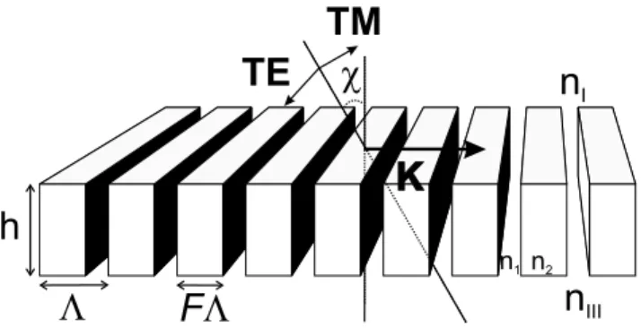
Fig. 3.—ZOG scheme presenting the main grating parameters: the grating vectorjKj ¼ 2"/!, perpendicular to the grating lines, where ! is the period; the grating depth h; and the so-called filling factor F, such that F! is the width of the grating ridges. The vectors TE and TM are the vectorial orthogonal po-larization components of the#-incident light. Here nIand nIIIare the refractive indices of the incident and transmitting media, respectively. The parameters n1 and n2are the refractive indices of the grating itself (in our case, n1¼ nIand n2¼ nIII). Finally, TE is the transverse electric vibration, where the electric field vector is perpendicular to the plane of incidence (the plane of incidence is defined by the grating normal and the direction of the incoming light, in our case by the grating normal and the grating vector), and TM is the transverse magnetic one (the electric field vector lies in the plane of incidence).
Bomzon et al. 2002; Levy et al. 2004). Applications are numer-ous: for example, polarimetry, laser-beam shaping, laser machin-ing, tight focusmachin-ing, particle acceleration, and atom trapping. Space-variant ZOGs are typically described by a function rep-resenting the grating vector spatial variation,
K(s; p)¼ K0(s; p) cos %(s; p)s½ þ sin %(s; p)p); ð4Þ
where s and p are the Cartesian unit vectors and K0(s; p)¼
2"/!(s; p) is the grating vector modulus corresponding to the lo-cal period!(s, p). Here %(s, p) is the local direction of the grat-ing vector with respect to s, the space-variant gratgrat-ing vector always being perpendicular to the local grating lines (see Fig. 4). In polar coordinates, we have
K(r; !)¼ K0(r; !) cos %½ 0(r; !)rþ sin %0(r; !)w); ð5Þ
where r andw are the polar coordinate unit vectors. Here %0(!, r) is the local direction of the grating vector with respect to r (see Fig. 4). Let us now consider the general case of the spiral geo-metric phase space-variant ZOGs. The grating groove direction in this case is given by%(s; p)¼ lp!/2 or %0(r; !)¼ (lp/2% 1)!,
where lp is the so-called topological Pancharatnam charge (a
nonsigned integer; see Appendix B). The grating vector there-fore becomes
K(r; !)¼ K0(r; !) cos (l# ! p=2% 1)!"rþ sin (l! p=2% 1)!"w$:
ð6Þ The continuity of the grating grooves is ensured by imposing : < K ¼ 0, which also implies that the grating vector derives
from a grating function# (K¼ :#). Integration over an arbi-trary path yields
#(r; !)¼ 2" r0 !0 r0 r % &lp=2%1 cos (lp=2% 1)! (lp=2% 1) ; lp6¼ 2; 2" r0 !0 f (r); lp¼ 2: 8 > > < > > : ð7Þ
This function describes a family of binary gratings depend-ing on the topological charge lp (Fig. 5). Let us remark that
the continuity criterion has been introduced for manufacturing convenience. In the lp¼ 2 case, the circular symmetry allows the
choice of any pure radial function. The AGPM corresponds to
#AGPM(r; !)¼ 2"
r !0
; lp¼ 2: ð8Þ
The family of spiral phase space-variant ZOGs creates an ‘‘optical vortex.’’ Indeed, at the center of these components, the phase possesses a screw dislocation inducing a phase singular-ity, i.e., an optical vortex. The central singularity forces the in-tensity to vanish by a total destructive interference, creating a dark core. This dark core propagates and is conserved along the optical axis. Whether a dark core is created in the pupil or focal plane of a telescope will determine the way it further evolves. Swartzlander (2001) proposed to create an optical vortex in the pupil plane to peer at the faint monochromatic signal in the re-layed focal plane with appropriate filtering. In this paper, we propose to do the inverse, i.e., to create an optical vortex in the focal plane, filter in the relayed pupil plane, and make the detec-tion in a final image plane. This soludetec-tion is theoretically much more attractive, as we will see. Furthermore, the ZOG’s unique properties permit an efficient broadband use.
2.3. AGPM Coronagraph
The AGPM coronagraph corresponds to the spiral phase of topological charge lp¼ 2, implying that the Pancharatnam
phase (see Appendix B) undergoes two 2" phase jumps within one revolution around the optical axis (see Fig. 6). This phase modification results solely from the polarization manipulation and is purely geometrical in nature. In the lp¼ 2 case, a given
polarization state repeats itself 2lp¼ 4 times. This point is
ar-gued for the linear polarization case inx A1 (a full analytical treatment of the polarization using space-variant Jones matrices is presented in Appendix A). We also show inx A2 that the
Fig. 4.—Space-variant ZOG vectorial analysis. Here s and p are the unit vectors of the chosen Cartesian basis, whereasw and r are the polar coordinate unit vectors. In addition, TE (transverse electric) and TM (transverse magnetic) are the polarization unit vectors according to the local grating line orientations. By definition, in normal incidence, the TE ( TM ) components are orthogonal ( parallel) to the local grating vector K(s, p) [¼ K(!; r)], spanning angles %(s, p) and%0(!, r) with respect to s and r, respectively. Finally,!(s, p) [ = !(!, r)] is the grating period.
Fig. 5.—Binary grating geometry for topological charges lpranging from 1 to 6. Only the lp¼ 2 geometry possesses the required circular symmetry for use with constant ZOG parameters, which permit achromatization. The component centers have been occulted for presentation purposes.
Jones vector for the output components can also be described in a helical polarization basis, with right-handed (R@) and
left-handed (L’) circularly polarized input fields. In this particular
case and under ideal conditions, we obtain at the output
R@¼ 0 ei(2!%"=2) ' ( ; L’ ¼ e%i(2!þ"=2) 0 " # : ð9Þ
The Pancharatnam phase clearly appears as the argument of the exponential, $p¼ 2!. Therefore, within one revolution,
i.e.,!¼ 2", one easily confirms that $p¼ 2(2"). In addition,
the helical basis allows us to decouple the output polarization components. This facilitates the forthcoming Fourier analysis. We demonstrate in Appendix C, thanks to Sonine’s integral (Sneddon 1951, p. 55), that in the lp ¼ 2 configuration the vortex
propagation up to the relayed pupil plane evolves into a perfect destructive interference, totally rejecting the starlight outside the geometric pupil area (we also analytically demonstrate that the perfect attenuation holds true for even values of lp). Like the
FQ-PM, the theoretical attenuation of the AGPM is therefore infinite in the perfect achromatic and circular filled pupil case ( Riaud et al. 2001). We have also chosen the lp¼ 2 case for the
following reason: in order to be achromatic, the space-variant ZOG local characteristics (grating period, depth, and filling fac-tor) are well defined and do not tolerate any departure from op-timal values within the tolerances (seex 4). We note in Figure 5 that only the lp¼ 2 case affords the required symmetry to
ful-fill this constraint. The other configurations (lp6¼ 2) all imply a
variation of the grating period that would destroy the achromatic characteristics of the phase shift. Moreover, such a variation of the period could lead the grating to exit the subwavelength domain with dramatic consequences: higher diffraction orders would show up.
The AGPM implementation of the space-variant ZOG is thus totally circularly symmetric. The grating vector is constant in modulus and aligned with the radius. In other words, the AGPM coronagraph can be seen as a FQ-PM coronagraph in polariza-tion. Indeed, if we consider the four cardinal points on the AGPM, the resulting phase shift distribution is analogous to the FQ-PM for each parallel potentially interfering polarization state (see Fig. 7). This argument holds true for each azimuth angle and for each ra-dius, and thus for the whole focal plane.
3. NUMERICAL RESULTS IN A REALISTIC CASE We have performed realistic numerical simulations that rely on a three-stage modeling:
1. A ‘‘rigorous coupled wave analysis’’ stage, where the form birefringence of the local grating is optimized, leading to the space-variant ZOG Jones matrix JZOG(s, p). At this stage,
the final performance of the coronagraph can already be quan-tified by the null depth.
2. The analytical polarization treatment based on Jones cal-culus, which gives the spatial distribution of the linear/helical polarization components of the incident light. We use for this step the results obtained in Appendix A.
3. A scalar far-field Fourier propagation coronagraphic code for each polarization state.
To simulate the grating response and calculate the form bire-fringence"nform¼ "nTE%TM in the subwavelength and
reso-nant domain (!' k), scalar theories of diffraction dramatically fail. The vectorial nature of light must be taken into account, implying a resolution of the Maxwell equations by the so-called rigorous coupled wave analysis (RCWA; Moharam & Gaylord 1981). RCWA gives the full diffractive characteristics of the simulated structure.
The ZOG form birefringence optimization has already been ex-tensively presented in Mawet et al. (2005) in the context of the FQ-PM achromatization for the H, K, and N bands (4QZOG). We focus here on the mostly used K band, but the conclusions are applicable to other band filters. In Figure 8 we present the RCWA results for a subwavelength surface-relief grating engraved on the surface of a diamond (C) or ZnSe substrate and covered by a 'k/4 antireflective (AR) layer of YF3. The latter settles at the
bottom of the grooves and on top of the grating ridges. The null depth, which characterizes the darkness of the destructive inter-ference taking place in the relayed pupil plane of the telescope, takes into account the phase errors with respect to ", &(k) ¼ "$TE%TM(k) % ", and amplitude mismatches q(k) ¼ 'TE(k)/
'TM(k) in the following way:
N (k) ¼ 1% ffiffiffiffiffiffiffiffi q(k) p ! "2 þ &(k)2pffiffiffiffiffiffiffiffiq(k) 1þpffiffiffiffiffiffiffiffiq(k) ! "2 : ð10Þ
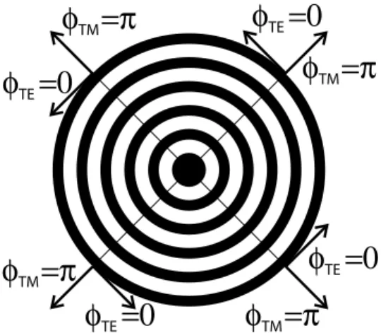
Fig. 6.—Pancharatnam phase ramp of the AGPM coronagraph:$p¼ 2!. The associated topological charge is lp¼ 2. Within one revolution around the optical axis, i.e.,!¼ 2", one easily confirms that $p¼ 2(2").
Fig. 7.—AGPM scheme and analogy with the FQ-PM coronagraph. The AGPM can be seen as a polarization FQ-PM. The parallel potentially interfering polarization states are out of phase according to the FQ-PM focal plane phase shift distribution. Here$TEand$TMare the output phases of the polarization components TE and TM such that"$TE%TM¼ j$TE% $TMj ¼ ".
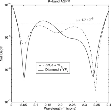
We can notice in Figure 7 the efficiency of the ZOG solution in solving the chromaticity problem for the K band with a mean null depth(' 1:7 ; 10%5. As said before, deep nulls can also be
achieved for other usual band filters (see Table 1). It must be noted that the optical throughput efficiency of the optimized ZOG is >90%. For the sake of clarity, the third stage of the AGPM simulations (Fourier propagation) has been performed for the K band only. We have used an IDL code for Fraunhofer diffraction analysis (Riaud et al. 2001). To minimize the aliasing effect of the fast Fourier transform, we have used large arrays (up to 2048; 2048) for the calculation. The intrinsic performance of the coronagraph will be limited by the phase residuals with respect to" and the transmittance mismatches between the two polar-ization states TE and TM, as well. We have also assumed wave front qualities ofk0/250 rms, wherek0is the central wavelength
of the considered filter. In our case (K band:k0¼ 2:2 (m), this
hypothesis leads therefore to wave front qualities of'k/70 rms, withk ¼ 632:8 nm. This is quite a severe but somewhat
realis-zones induced by the FQ-PM/4QZOG quadrant transitions. The final K-band polychromatic image reveals the simulated compan-ion 15 mag fainter. The coronagraphic profile functcompan-ions of the angular separation ink/d (d is the telescope diameter) show a peak-to-peak attenuation of about 10%5( Fig. 10). The speckle level of'10%7is quickly reached at a fewk/d. The AGPM corona-graphic behavior is very similar to the achromatic 4QZOG coro-nagraph ( Mawet et al. 2005), but with a total symmetry.
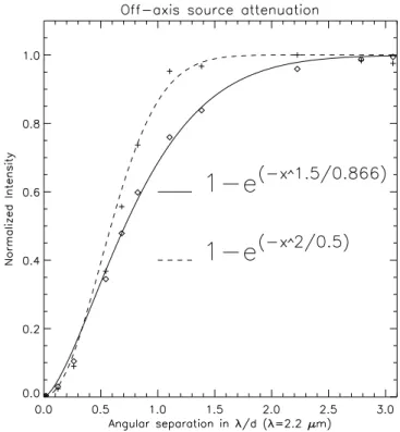
Figure 11 presents the attenuation of the off-axis simulated companion, which is also quite similar to the FQ-PM/4QZOG in its best configuration, i.e., only along the two diagonals. Indeed, as mentioned in the introduction, the FQ-PM/4QZOG quadrant transitions induce a nonnegligible attenuation of the superim-posed circumstellar features lying on them. These dead zones represent quite a significant portion of the focal plane (about 10% at 6k/d). Thanks to the perfect AGPM circular symmetry, this problem does not exist anymore. We also note that the in-ner working angle of the AGPM is very good, peering well under k/d. As far as stellar leakage is concerned, numerical simulations show that it increases as%2
k/dclose to the optical axis, just as the
FQ-PM /4QZOG (where%k /dis the angle from the optical axis).
In fact, calculations show that for a vortex of topological charge lp, the stellar leakage grows as%
lp
k/d.
4. MANUFACTURING
In the K-band diamond AGPM case, for instance, the local ZOG optimal parameters are
1. period,!¼ 740 nm; 2. filling factor, F¼ 70%; 3. total depth, h¼ 3:240 (m; and 4. AR layer thickness, 420 nm.
The fabrication of the AGPM coronagraph implies no devel-opments other than those for the 4QZOG (Mawet et al. 2005), which is currently under assessment in diamond by Uppsala University’s Angstro¨m Laboratory ‘‘Adamantis AB’’ (Karlsson
TABLE 1
AGPM Achromatization ( Null Depth) for Various Band Filters: Visible, Near-IR and Mid-IR Filter
Parameter V (Rk¼ 5:5) I (Rk¼ 3:75) J (Rk¼ 4:16) H (Rk¼ 4:7)
Null depth (on-axis)... 2; 10%5 1:35 ; 10%4 6:5 ; 10%5 3:5 ; 10%5 Expected contrast (at 3k /d )... 1:66 ; 10%7 1:12 ; 10%6 5:42 ; 10%7 2:92 ; 10%7
Grating period (nm) ... 280 (n-LAF32) 305 (C) 400 (C) 525 (C)
K (Rk¼ 5:5) L0(Rk¼ 6:3) M (Rk¼ 16:6) N (Rk¼ 4:86) Null depth (on-axis)... 1:7 ; 10%5 8:4 ; 10%6 5; 10%7 4; 10%5 Expected contrast (at 3k /d )... 1:42 ; 10%7 7; 10%8 4:2 ; 10%9 3:3 ; 10%7
Grating period ((m) ... 0.740 (C) 1.28 (C) 1.7194 (C) 3.29 (C)
Notes.—Here Rk¼ k/"k is the spectral resolution. C stands for CVD diamond, while n-LAF32 refers to a high-index Schott glass.
Fig. 8.—K-band AGPM coronagraph null depth vs. wavelength. The solid curve is for the diamond YF3AR coated ZOG. The dot-dashed curve is for the ZnSe YF3AR coated one. The mean null depth over the whole K band is (' 1:7 ; 10%5.
mask. We note that the phase mask effect is close to that obtained for the FQ-PM coronagraph, but without any discontinuity left. (c) Picture showing the starlight rejection in the relayed pupil plane. The diffraction pattern is annular and symmetric in this configuration. (d ) Resulting coronagraphic image for the full K band, where the fainter companion is clearly visible. All images are displayed with a nonlinear scale.
Fig. 10.—Theoretical radial profiles obtained with the K-band AGPM. The solid line shows the coronagraphic profile. The residual central peak is due to the effect of the phase errors (residual chromatism) around the" phase shift. In this case, a starlight speckle level of 10%7is reached at 3k/d. The dashed line shows the polychromatic Airy pattern for the full K band. The diaphragm (Lyot stop) is open at 80%.
Fig. 11.—Degradation of the coronagraphic performance function of angular separation. This figure compares the companion attenuation for the AGPM vs. the classical 4QZOG in its best configuration, i.e., at least 1k/d away from a quadrant transition. This degradation is measured on the total energy. The solid line shows the exponential fit on the simulated data (open diamonds) for the AGPM coronagraph. The dashed line shows the exponential fit on the simulated data (plus signs) for the FQ-PM/4QZOG coronagraph.
the parameters has been presented in Mawet et al. (2005). The conclusion was that the tolerance on the filling factor was at the 1% level but also that if the manufacturing process was inter-actively conducted, then errors on the filling factor definition could be compensated a posteriori. The next fabrication steps consist in transferring the mask pattern into the substrate by an appropriate reactive plasma beam etching down to the desired depth, followed by the k/4 AR layer deposition. Assuming a classical realistic resolution of 10 nm in thickness (2%) for the AR layer sputtering, we can ensure a grating etching depth tolerance of about 20 nm at the null depth level of 10%5. This value is well within reach with current technologies, especially if in situ real-time monitoring of the grating parameters is imple-mented during the fabrication process (Lalanne et al. 1999).
5. DISCUSSION
In this paper, we have presented a new phase mask corona-graph that is free from any ‘‘dead zone,’’ thanks to its perfect circular symmetry, and inherently quasi-achromatic. The AGPM coronagraph consists in an optical vortex induced by a
space-on a single-pupil telescope either in space or space-on the ground (with an adaptive optics system) to dramatically enhance the dynamics. It could also be used at the Fizeau or densified focus of an in-terferometer (Labeyrie 1996; Boccaletti et al. 2000; Riaud et al. 2002) to take advantage of the increased resolution. However, in the Fizeau configuration, phase coronagraphs are limited by the cross-talk between the different interferometer subpupils, whereas in the densified one, the limitation comes from diffraction effects induced by residual gaps between the joined subpupils ( P. Riaud et al., in preparation). Nevertheless, the AGPM should be seriously regarded as an integrated high-contrast solution to be imple-mented in NASA’s Terrestrial Planet Finder and/or ESA’s in-frared space interferometer, DARWIN, missions.
D. M. acknowledges the financial support of the Belgian ‘‘Fonds pour la formation a` la Recherche dans l’Industrie et dans l’Agriculture.’’ P. R. and J. S. acknowledge the financial support of the ‘‘Poˆle d’Attraction Inter-Universitaire.’’
APPENDIX A
POLARIZATION TREATMENTS
Let us perform a full space-variant polarization and phase analysis of the component, assuming first that it induces an optical vortex of lpth order. Representing it by a space-variant Jones matrix, one can find the resulting wave front for any incident polarization,
Jvortex(s; p)¼ M %(s; p)½ )JZOG(s; p)M %(s; p)½ )%1: ðA1Þ
Here JZOG(s, p) actually describes the effects of the local ZOG form birefringence that transforms the phase (TE% TM vectorial
phase shift"$TE%TM) and amplitude (TE% TM differential Fresnel parasitic reflection) of the outgoing beam,
JZOG(s; p)¼
'TE 0
0 'TMei"$TE%TM
' (
; ðA2Þ
where'TEand'TMare the local grating transmittances along the TE and TM directions of polarization, respectively (the
trans-mittances can be assimilated to diffraction efficiencies). These transtrans-mittances are different because of the different Fresnel reflection coefficients resulting from the existence of the two effective indices that give birth to the form birefringence (see eq. [2]). For the sake of simplicity, we write"$¼ "$TE%TM. The parameter M [%(s, p)] is the %-dependent rotation matrix
M½%(s; p)) ¼ cos% %sin % sin% cos%
' (
; ðA3Þ
where%(s, p) is the grating vector angle that defines the local grating line orientations. Thus, we have
Jvortex(s; p)¼
'TEcos2%þ 'TMsin2%ei"$ sin% cos % 'TE% 'TMei"$
* +
sin% cos % 'TE% 'TMei"$
* +
'TMsin2%þ 'TEcos2%ei"$
" #
: ðA4Þ
In order to carry out the analysis of the component with the scalar Fourier coronagraphic propagation code, we have to chose a basis to project the incident polarization (natural or not).
A1. LINEAR BASIS
We can decompose the problem by projecting the incident polarization on the orthogonal linear (s, p) basis. Therefore, we have the following Jones vectors as linear polarization inputs:
Ep¼ 1 0 ' ( ; ðA5Þ Es¼ 0 1 ' ( : ðA6Þ
Multiplying them both by the vortex Jones matrix Jvortex(s, p), we obtain
Ep¼
'TEcos2%þ 'TMsin2%ei"$
sin% cos % '* TE% 'TMei"$+
" #
; ðA7Þ
Es¼
sin% cos % '* TE% 'TMei"$+
'TMsin2%þ 'TEcos2%ei"$
" #
; ðA8Þ
respectively, corresponding to the output polarization states to be injected in a subsequent coronagraphic code. In the perfect case (exact" phase shift, i.e.,"$TE%TM¼ " and unitary matched efficiencies 'TE¼ 'TM¼ 1) for the AGPM configuration (lp¼ 2 and
thus%¼ lp!/2¼ !, where ! is the azimuthal polar coordinate), we have
Ep¼ cos 2! sin 2! ' ( ; ðA9Þ Es¼ sin 2! %cos 2! ' ( : ðA10Þ
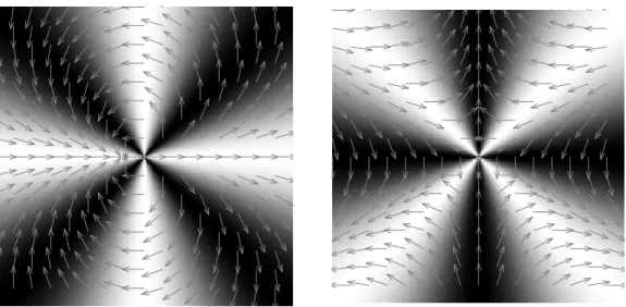
This implies that in the AGPM case (lp¼ 2) an input linear polarization, which is horizontal, for example, will locally rotate by
twice the azimuthal angle!, as shown in Figure 12, where the corresponding output vectorial field and intensity response to linear polarization are displayed.
A2. HELICAL BASIS
The analysis can be decoupled by projecting the incident vectorial field on a helical basis, i.e., with right- and left-handed circular polarization unit vectors
R@¼ 1
0 ' (
; ðA11Þ
Fig. 12.—AGPM response to linear polarization. Left: Intensity map for an input linear horizontal polarization seen by a horizontal analyzer. Right: Same, but for an input linear vertical polarization. Arrows show the corresponding vectorial polarization field that has been submitted to the rotation given by eqs. (A9) and (A10). We clearly notice that a given polarization state repeats itself four times.
U¼ ffiffiffi 2 p 1 %i : ðA14Þ Finally, we have Jvortex@’(s; p)¼12 'TEþ 'TMei"$ * + 1 0 0 1 ' ( þ12 'TE% 'TMei"$ * + 0 ei2% e%i2% 1 " # : ðA15Þ
In the perfect case where'TE¼ 'TM¼ 1 and "$ ¼ ", and in the AGPM configuration case where lp¼ 2 and thus % ¼ lp!/2¼ !,
where! is the azimuthal polar coordinate, we obtain as output
R@¼ 0 ei(2!%"=2) ' ( ; ðA16Þ L’¼ e%i(2!þ"=2) 0 " # : ðA17Þ
Therefore, the two output polarization beams are orthogonal and decoupled in the helical basis.
APPENDIX B
PANCHARATNAM TOPOLOGICAL CHARGE
The so-called Pancharatnam phase has been introduced to measure the comparison of the phases of two light beams in different states of polarization. It is defined as the argument of the inner product of the two Jones vectors describing the two light beams to be phase compared,
$p¼ arg hE(!; r); E(0; r)i: ðB1Þ
We can also define the associated topological charge of the beam, which is a nonsigned integer giving the number of times that the azimuthal angle rotates about the phase disclination (topological defect),
lp¼
1 2"
I
:$pds: ðB2Þ
In the AGPM case,$p¼ 2! (lp¼ 2), which implies that the polarization state repeats itself 2lp¼ 4 times (see Fig. 12).
APPENDIX C
PERFECT REJECTION PROOF
Let us now analytically compute the pupil plane intensity distribution. The latter can be expressed as the Fourier transform of the product of the Airy disk function (a filled circular pupil is assumed) and the mask phase ramp. We have seen inx A2 that the mask phase in the helical basis takes the simple decoupled form ei(lp!%"/2). Therefore, in the Fourier-plane polar coordinates (), ) we have
Apup(); ; lp)¼ FT 2J1(2"Rtelr) 2"Rtelr ei(lp!%"=2) ' ( (); ): ðC1Þ Explicitly, Apup(); ; lp)¼ %i Z 1 0 Z 2" 0 2J1(2"Rtelr) 2"Rtelr ei(lp!)e%2i)r cos(!% )r dr d!; ðC2Þ
where we recognize the nth order Bessel function Jn. Indeed, various integrals can be expressed in terms of Bessel functions, Jn(z)¼ 1 2"i%n Z 2" 0 eiz cos$ein$d$; ðC3Þ and thus we have
Apup(); ; lp)¼ %ilp%1 2eilp Rtel Z 1 0 J1(2"Rtelr) Jlp(2")r) dr: ðC4Þ C1. AGPM CORONAGRAPH: lp¼ 2
The previous result in the lp¼ 2 case is the so-called Sonine’s integral (Sneddon 1951, p. 55),
S¼ Z 1 0 y1þ(%kJk(ay) J((by) dy¼ 0; 0< a < b; b((a2% b2)k%(%1 2k%(%1ak$(k % (); 0< b < a: 8 < : ðC5Þ
Thus, taking lp¼ 2, we have
Apup(); ; lp¼ 2) ¼ 0; 0< ) < Rtel; ei2 ")2; 0< Rtel< ): 8 < : ðC6Þ
We have demonstrated that in the perfect case for lp¼ 2 (AGPM), the light is entirely rejected outside the geometric pupil area.
C2. GENERALIZATION TO lpTH-ORDER VORTICES
Equation (C4) corresponds to the so-called Hankel transform of lPth order of the Bessel J1function. This transform has an analytical
solution (Abramowitz & Stegun 1972, p. 487),
Apup(); ; lp)¼ %i1%lp 2eilp Rtel (2"))lp(2"R tel)%lp%1 $(1þ lp=2) $(lpþ 1)$(1 % lp=2) 2F1 lpþ 1 2 ; lp 2; lpþ 1; )2 R2 tel % & ; 0< ) < Rtel; (2"))%2(2"Rtel) $(1þ lp=2) $(2)$(lp=2)2 F1 lpþ 1 2 ; 2% lp 2 ; 2; )2 R2 tel % & ; ) > Rtel; 8 > > > < > > > : ðC7Þ
where we recognize the gamma$ and hypergeometric2F1functions. This function shows perfect attenuation for even lpvalues only,
Apup(); ; lp)¼ 0; ) < Rtel and lp¼ 2; 4; 6; : : : : ðC8Þ
REFERENCES Abramowitz, M., & Stegun, I. A. 1972, Handbook of Mathematical Functions
( New York: Dover)
Baudoz, P., Boccaletti, A., Riaud, P., Cavarroc, C., Baudrand, J., Reess, J. M., & Rouan, D. 2005, PASP, submitted
Biener, G., Niv, A., Kleiner, V., & Hasman, E. 2002, Opt. Lett., 27, 1875 Boccaletti, A., Riaud, P., Baudoz, P., Baudrand, J., Rouan, D., Gratadour, D.,
Lacombe, F., & Lagrange, A.-M. 2004, PASP, 116, 1061
Boccaletti, A., Riand, P., Moutou, C., & Labeyrie, A. 2000, Icarus, 145, 628 Bomzon, Z., Niv, A., Biener, G., Kleiner, V., & Hasman, E. 2002, Appl. Opt.,
41, 5218
Brillet, A., Vinet, J.-Y., Loriette, V., Mackowski, J.-M., Pinard, L., & Remillieux, A. 2003, Phys. Rev. D, 67, 102006
Gay, J., & Rabbia, Y. 1996, CR Acad. Sci. Paris, 332, 265
Gratadour, D., Rouan, D., Boccaletti, A., Riaud, P., & Cle´net, Y. 2005, A&A, 429, 433
Karlsson, M., Hjort, K., & Nikolajeff, F. 2001, Opt. Lett., 26, 1752 Karlsson, M., & Nikolajeff, F. 2003, Opt. Express, 11, 502 Kikuta, H., Ohira, Y., & Iwata, K. 1997, Appl. Opt., 36, 1566 Labeyrie, A. 1996, A&AS, 118, 517
Lalanne, P., Pichon, P., Chavel, P., Cambril, E., & Launois, H. 1999, Appl. Opt., 38, 4980
Levy, U., Tsai, C.-H., Pang, L., & Fainman, Y. 2004, Opt. Lett., 29, 1718
Lyot, B. 1939, MNRAS, 99, 580
Mackowski, J. M., Pinard, L., Dognin, L., Ganau, P., Lagrange, B., Michel, C., & Morgue M. 1999, Opt. Quantum Electron., 31, 507
Mawet, D., et al. 2005, Appl. Opt., in press
Moharam, M. G., & Gaylord, T. K. 1981, J. Opt. Soc. Am., 71, 811 Mouillet, D., Fusco, T., Lagrange, A.-M., & Beuzit, J.-L. 2003, in Astronomy
with High Contrast Imaging, ed. C. Aime & R. Soummer ( Les Ulis: EDP Sciences), 193
Niv, A., Biener, G., Kleiner, V., & Hasman, E. 2003, Opt. Lett., 28, 510 Nordin, G. P., & Deguzman, P. C. 1999, Opt. Express, 5, 163
Riaud, P., Boccaletti, A., Baudrand, J., & Rouan, D. 2003, PASP, 115, 712 Riaud, P., Boccaletti, A., Rouan, D., Lemarquis, F., & Labeyrie, A. 2001, PASP,
113, 1145
Riaud, P., et al. 2002, A&A, 396, 345
Roddier, F., & Roddier, C. 1997, PASP, 109, 815
Rouan, D., Riaud, P., Boccaletti, A., Cle´net, Y., & Labeyrie, A. 2000, PASP, 112, 1479
Rouan, D., et al. 2004, A&A, 417, L1
Smith, B. A., & Terrile, R. 1984, Science, 226, 1421
Sneddon, I. N. 1951, Fourier Transforms ( New York: McGraw-Hill ) Soummer, R., Dohlen, K., & Aime, C. 2003, A&A, 403, 369 Swartzlander, G. A., Jr. 2001, Opt. Lett., 26, 497