Université du Québec
Institut National de la Recherche Scientifique Centre Énergie Matériaux Télécommunications
ULTRA WIDEBAND STACKED RECTANGULAR
DIELECTRIC RESONATOR ANTENNA
Par
Mohamed Sedigh Bizan
Mémoire présenté pour l’obtention du grade de Maître ès sciences (M.Sc.)
Jury d’évaluation
Président du jury et Prof. Serioja Ovidiu Tatu examinateur interne INRS-Énergie Matériaux Télécommunications Examinateur externe Prof. Amari, Smain
Génie électrique et informatique Collège militaire royal du Canada Directeur de recherche Prof. Tayeb A. Denidni
INRS-Énergie Matériaux Télécommunications
ABSTRACT
This thesis is a presentation of a design and fabrication of ultra-wideband stacked rectangular dielectric resonator antenna (UWB-RDRA), where the effect of position perturbations on the bandwidth of an aperture coupled dielectric resonator antenna (DRA) is studied. The proposed antenna takes advantage of two low-Q modes which have overlapping bandwidths so as to achieve an ultra-wideband operation. This can be achieved by using two combinations of stacked DRAs for the analysis: larger over smaller (LOS), and smaller over larger (SOL). Different position perturbations on the transmission line (TL), LOS, and SOL are applied to widen the matching bandwidth of the antenna.
The performance of the proposed antenna is compared with the conventional antenna designed with no perturbations. The proposed antenna not only provides 5:1 ultra-wide matching bandwidth (from 2.7 GHz to 13.6 GHz), but also results in the highest gain of 9 dBi, which is 2 dBi more than the antenna designed with conventional method with no perturbation. The proposed antenna, therefore, consists of the dielectric constant of 6.15 and 9.8 that are stacked vertically in order to acquire a bandwidth that is more improved as compared to the conventional RDRA. A use of 50 Ω microstrip line is required in the proposed antenna to act as a feeding mechanism. The physical parameters of stacked RDRA are also optimized by extensive simulations using Computer Simulation Technology (CST) software.
The parameters of this antenna are 65x50x5 mm3 and its grounded substrate size is 108x90 mm2. The prototype is fabricated and measured. The measured results and simulated results show a good agreement. This prototype antenna is designed to cover the band from 2.7 GHz to 13.6 GHz. This proposed antenna is therefore suitable for wireless (Wi-MAX) and (WLAN) application bands.
Dedicated to
This thesis is dedicated to special people in my life:
my beloved parents, my teachers, my lovely wife who always
inspires me, my wife’s family for their encouragement and
support, my son Mahmud, as well as my coming child.
ACKNOWLEDGMENT
In the name of Allah, Most Gracious, Most Merciful. Praise be to Allah, the Cherisher, and Sustainer of the Worlds. First and foremost, I am very grateful to my God for his blessings, graces. Who gave me the strength and will to complete this study that without his helps it would not have been accomplished.
Till this moment, this work is the higher achievement ever in my life and it would be impossible to go through it without acknowledging the people who supported me and as well as believing in me.
I acknowledge the support of my supervisor Prof. Tayeb A. Denidni for his incomparable assistance and guidance all through the research. I have highly appreciated him for his subsequent and constant encouragement that he has always offered by giving his critics on my work bit by bit as I progress. I am therefore grateful for him for having given me the support and instilling confidence in me. His trust and support always gave me inspiration in many significant moments of arriving in the right decisions and I am glad to have worked with him in my entire course.
I would also like to thank all my friends, and more so my classmates, every thought and mind stimulating discussions we had as a group, which consequentially prompted us to brainstorm and think beyond the normal reasoning. I have enjoyed their companionship so much during my stay at INRS. I would like to thank all those who made my stay in INRS a memorable and rewarding experience.
Last but not least, I would like to thank my parents who taught me the value of hard work by offering their own example. They gave me their gigantic support during the whole tenure of my stay at Quebec University.
TABLE OF CONTENTS
Abstract………..…i Acknowledgments……….…….iii Table of contents……….……iv List of Tables………...….……viii List of Figs.……….…...…ixList of Abbreviations and symbols……….……..…..xiii
Chapter One: Introduction……….……….……….1
1.1 Introduction………....…1
1.2 Project aim and objectives………...3
1.3 Thesis organization………..………...….3
Chapter Two: Dielectric resonator antennas literature………5
2.1 Introduction to DRA……….…...…..5
2.2 Dielectric resonator antenna bandwidth and bandwidth enhancement………..….6
2.3 Ultra-wideband dielectric resonator antenna………..…..8
2.4 Dielectric resonator antenna concept………..……..8
2.4.1 Dielectric resonator antenna characteristics………....…10
2.4.2 Dielectric resonator antenna design………..11
2.4.3 Dielectric resonator antenna size………..…..…..11
2.4.4 Dielectric resonator antenna shape………..……….12
2.4.4.1 Famous shapes of Dielectric Resonator Antenna………14
2.4.4.1.1 Cylindrical DRA……….…….…..14
2.4.4.1.3 Rectangular DRA……….………16
2.4.5 Resonant frequency……….17
2.2.5.1 Stacked method………..………18
2.2.5.2 Coplanar parasitic method……….19
2.2.5.3 Embedded method………..21
2.5 Dielectric resonator antenna performance………21
2.5.1 Radiation Q factor……….……22
2.5.2 Radiation pattern……….….23
2.5.3 Input impedance and Bandwidth………...25
2.5.4 Directivity and Gain……….…….26
Chapter Three: Design of new ultra-wideband Dielectric Resonator Antenna………29
3.1 Introduction……….………29
3.2 Ultra-wideband dielectric resonator antennas (two layers of DRs)………….……..30
3.2.1 Aperture Coupled Stacked DRA with Conventional Method (with no offset)………30
3.2.2 Proposed Aperture Coupled DRA with Improved Performance…………32
3.2.3 Parametric study………...…32
3.2.4 Simulation and measurement results and discussion………....…34
3.3 Aperture Coupled Stacked DRA (three layers of DRs)………..……40
3.3.1 Structure and design……….…...…40
3.3.2 Simulation results and discussion………..…………...…41
3.4 Aperture Coupled Stacked DRA………..…..43
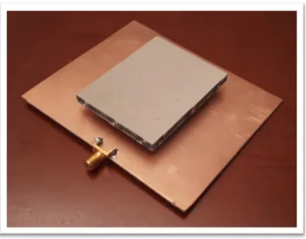
3.4.1 Antenna fabrication………...….…..43
Chapter Four: Conclusion………..……….……….48
4.1 Conclusion………..48
4.2 Future Works……….49
Chapitre Cinq: Sommaire……….……50
5.1.1 Résumé………..…..50
5.1.2 Introduction……….…….51
5.1.3 But et objectifs du projet……….……..52
5.1.4 Organisation de la thèse………...…….52
5.2 Examen des antennes à résonateur diélectrique……….……53
5.2.1 Introduction………53
5.2.2 Bande passante de l'antenne du résonateur diélectrique et amélioration de la bande passante………54
5.2.3 Antenne à résonateur diélectrique ultra large bande……….….55
5.2.4 Concept d'antenne à résonateur diélectrique……….……..55
5.2.4.1 Caractéristiques de l'antenne du résonateur diélectrique………56
5.2.4.2 Conception de l'antenne du résonateur diélectrique………..…..56
5.2.4.3 Taille de l'antenne du résonateur diélectrique……….…..…56
5.2.4.4 Forme de l'antenne du résonateur diélectrique………...…..56
5.2.4.4.1 Formes célèbres d'antennes à résonateur diélectrique…...57
5.2.4.4.1.1 DRA cylindrique………..…57 5.2.4.4.1.2 Hémisphère DRA……….……..57 5.2.4.4.1.3 DRA rectangulaire……….…….58 5.2.4.5 Fréquence de résonance……….….…58 5.2.4.5.1 Méthode empilée……….……..59 5.2.4.5.2 Méthode incorporée………..……60
5.2.5 Performance de l'antenne du résonateur diélectrique………….….….…60
5.2.5.1 Diagramme de rayonnement……….…….……..….60
5.2.5.2 Impédance d'entrée et bande passante……….…..……61
5.2.5.3 Directivité et gain………...61
5.3 Conception d'une nouvelle antenne à résonateur diélectrique ultra-large band…62 5.3.1.1 DRA empilée couplée à l'ouverture avec méthode conventionnelle….62 5.3.1.2 DRA couplée à l'ouverture proposée avec performance améliorée...63
5.3.1.3 Résultats de la simulation et discussion………...…….63
5.3.3 DRA empilée couplée à l'ouverture………....……68
5.3.3.1 Fabrication d'antennes……….……68
5.3.3.2 Simulation et résultats mesurés……….………….68
5.4.1 Conclusions……….70
5.4.2 Travaux futurs………...71
LIST OF TABLES
Table 3.1 The dimensions of the proposed antenna...31 Table 3.2 Comparison between two cases, conventional and the proposed.…………...38 Tableau 5.1 Les dimensions de l'antenne proposée………63
LIST OF FIGURES.
Fig. 1.1 DRA as an alternative to traditional low gain antenna elements [3]….……2
Fig. 2.1 Basic operation of transmitting and receive antennas [8]………...……5
Fig. 2.2 Photography of Marconi’s Fan Monopole antenna [11]………..…….6
Fig. 2.3 Techniques for bandwidth enhancement [13]………7
Fig. 2.4 An experimental laboratory prototype fed RDRA design [13]…………...…..9
Fig. 2.5 Dielectric resonator antenna characteristics………..….….10
Fig. 2.6 Various types and shapes of DR [29]………..………...…...13
Fig. 2.7 The configuration of cylindrical DRA……….14
Fig. 2.8 Geometry of a probe feeding of hemispherical DRA………....….15
Fig. 2.9 Geometry of the rectangular DRA………17
Fig. 2.10 Geometry of Stacked rectangular DRAs……….……18
Fig. 2.11 Geometry of co-planar parasitic method………...……20
Fig. 2.12 Antenna characteristics that determine its performance [5]……….21
Fig. 2.13 Radiation pattern in 3D and 2D representation………..23
Fig. 3.1 The basic structure of an aperture coupled stacked DRA………...….31
Fig. 3.2 The effect of DR1 shifting along X-axis (xx)………..…….33
Fig. 3.4 The effect of the width of DR2………..….34
Fig. 3.5 The simulation results of the conventional antenna S11 ……….……..35
Fig. 3.6 The simulation results of the conventional antenna again………..…..…...35
Fig. 3.7 Conventional antenna E-plane radiation patterns vs. frequency.……..…..36
Fig. 3.8 Conventional antenna H-plane radiation patterns vs. frequency …..……..36
Fig. 3.9 Proposed antenna with Perturbations S11……….…..….37
Fig. 3.10 Proposed antenna with perturbations, frequency vs. gain………...…….37
Fig. 3.11 Proposed antenna with perturbations, E-plane radiation patterns at 3 GHz………..………...39
Fig. 3.12 Proposed antenna with perturbations, H-plane radiation patterns at 3 GHz………..39
Fig. 3.13 The structure of the three stacked DRA………..…..40
Fig. 3.14 S11 vs. frequency of the three stacked DRA………..….41
Fig. 3.15 Gain vs. frequency of the three stacked DRA……….….……41
Fig. 3.16 Radiation pattern of the proposed antenna at frequencies 3.5, 5.4, and 10.0 GHz………42
Fig. 3.17 Fabricated Antenna………..……....43
Fig. 3.18 The antenna under test in measurement room……….……..…….44
Fig. 3.20 Amplitude of reflection coefficient of the proposed antenna………..…45 Fig. 3.21 Normalized radiation pattern of the proposed antenna at 3.5 GHz……..…46 Fig. 3.22 Normalized radiation pattern of the proposed antenna at 5.0 GHz………..46 Fig. 3.23 Normalized radiation pattern of the proposed antenna at 10.0 GHz………47 Fig. 3.24 Simulation and measured gain vs. frequency of the proposed antenna.…47 Fig. 5.1 DRA comme alternative pour les éléments d'antenne traditionnels
à faible gain ……….………51 Fig. 5.2 Fonctionnement de base des antennes d'émission et de réception ……...53 Fig. 5.3 Techniques d'amélioration de la bande passante ………...54 Fig. 5.4 Une ouverture de prototype de laboratoire expérimental couplée à un
modèle RDRA……….…………55 Fig. 5.5 Géométrie du DRA rectangulaire………..58 Fig. 5.6 Géométrie des DRA rectangulaires empilées……….…59 Fig. 5.7 Schéma de rayonnement en représentation 3D et 2D…………..…………61 Fig. 5.8 La structure de base du DRA empilé………63 Fig. 5.9 Résultats de la simulation de l'antenne conventionnelle,
fréquence vs. S11………...64
Fig. 5.10 Les résultats de la simulation de l'antenne conventionnelle,
Fig. 5.11 Résultats des diagrammes de rayonnement du plan E
de l'antenne conventionnelle en fonction de la fréquence……….…65 Fig. 5.12 Résultats des diagrammes de rayonnement du plan H
de l'antenne conventionnelle en fonction de la fréquence……….66 Fig. 5.13 Résultats de la simulation de l'antenne proposée avec Perturbations,
fréquence vs S11……….………..………66
Fig. 5.14 Les résultats de la simulation de l'antenne proposée avec des
perturbations par rapport à la fréquence pour le gain………67 Fig. 5.15 Résultats de la simulation de l'antenne proposée avec perturbations
pour les diagrammes de rayonnement du plan E à 3 GHz………67 Fig. 5.16 Résultats de la simulation de l'antenne proposée avec perturbations
pour les diagrammes de rayonnement du plan H à 3 GHz……….…..68 Fig. 5.17 Antenne fabriquée………..….…..…68 Fig. 5.18 L'antenne sous test dans la salle de mesure………..…….…68 Fig. 5.19 Amplitude du coefficient de réflexion de l'antenne proposée……..…….…..69 Fig. 5.20 Diagramme de rayonnement normalisé de l'antenne proposée à 3,5 GHz..70 Fig. 5.21 Diagramme de rayonnement normalisé de l'antenne proposée à 5,0 GHz..70 Fig. 5.22 Diagramme de rayonnement normalisé de l'antenne proposée à 10,0 GHz.70
LIST OF ABBREVIATIONS AND SYMBOLS
UWB Ultra-Wide Band
DRA Dielectric Resonator Antenna LOS Larger Over Smaller
SOL Smaller Over Larger TL Transmission Line BW Band-width
MMIC Monolithic Microwave Integrated Circuit ɛr Relative Permittivity
λ0 free space wavelength
𝑓0 frequency resonance
c light velocity in free space TE Transverse Electric TM Transverse Magnetic E Electric field H Magnetic field Zin Input Impedance Z0 Output Impedance
VSWR Voltage Standing Wave Ratio RF Radio Frequency
MW Microwave RL Return Loss Q Quality factor
CHAPTER ONE: INTRODUCTION
1.1 Introduction
In today communication world, antennas play an essential and important role in wireless communication systems whether in the transmitter or receiver circuit. The antenna becomes a basic part of all wireless communication systems such as cell phones, satellite, navigation systems for transportation, Wi-Fi networks etc.
Since the first successful transmission that was done by Galileo Marconi, the wireless communication systems have grabbed a great attention of many researchers. In some applications, a number of antennas are required to work in different frequencies, polarization, and radiation patterns to meet the need of these applications, therefore, various shapes, kinds, and techniques of antennas have been discovered and invented, one of those techniques uses a dielectric as a resonator in antenna design, this type of antennas is known later as a dielectric resonator antenna (DRA).
The DRAs have received considerable attention. They are inexpensive promising solutions that are able to change their characteristics in order to adapt to their environment and fulfill the operational requirements.
In 1983, S. Long, M. McAllister, and L. Shen have proposed a cylindrical dielectric as a resonator in the antenna. In [1, 2], it was the first generation of dielectric antenna technology. Today, more than 800 publications have been put forward alongside couple dozen issued patents that entail the dielectric resonator antenna (DRA) technology [3].
The main characteristic for the DRA with concept leading to extra work that improves the performance of the DRA technology have been discovered and published by the several researchers, which led to conclude that this technology offered a good alternative for the extra low gain antenna elements, as illustrated in Fig. 1.1.
The DRA initially used the dielectric resonator in place of a resonator device to store energy.
Fig. 1.1: DRA as an alternative to traditional low gain antenna elements [3].
Researchers who have directed much of their attention in the applications of using DRA technology to replace both the elements of the traditional low gain antenna, microstrip patches, monopoles, dipoles, since it offered a lot of advantages over the more traditional concepts of the antenna [3].
During the mid-late 1990s, DRA research advances covered from two-element arrays to more complex arrays of planar phased arrays consisting of over 300 elements containing advanced phased-steering capabilities [3]. It is also during this period that the performance of low profile and compact designs, mutual-coupling analysis array elements, and circular polarized DRAs, multi-band and wide design, active/ tunable DRAs and the cropping of the antenna designs have been proposed [3].
During the early years of the DRA concept development, it was only possible to achieve a narrow bandwidth which was wider than the microstrip antenna. This narrow bandwidth limitation, therefore, limited the applications of the DRA designs. Despite this phenomenon, subsequent research has led to the DRA offering a wider bandwidth, e.g. a technique used in increasing the wideband is that of a rectangular DRA stacked on a vertical ground plane edge. A parasitic ring was placed on the top of the DR, hence bandwidth improved from 96% to 105%, from 92% to 100%, and from 107% to 119% [40].
Besides, the excitation of two radiation bands at the same time improves the DRA bandwidth since the fields are added. One of the bands is from the DRA while the
other remaining bandwidth is got from the feeding system like a hybrid design [4]. Multiple probes are a technique that is used in increasing the bandwidth [4].
The optimization of the impedance required the use of a crescent patch in feeding the DRA substantial bandwidth enhancement in the antenna design is provided by a parasitic cylindrical DRA [5, 6]. A natural control of a bandwidth behavior is therefore promoted by the rectangular DRA through adjustments of dimensional parameters like height, weight, and length [15]. Subsequent means of increasing the antenna bandwidth using stacked DRAs, embedded DRAs, or any other formations of DRA [1].
1.2 Project aim and objectives
The aim of this project is to investigate the DRA designs with improved performance in terms of bandwidth for wireless communications, sensing and energy harvesting at microwave frequencies. For this, we propose a stacked antenna concept. Techniques for increasing the performance of DRAs have been investigated during the project, by simulation with the CST Microwave Studio and then by experimentation, which is planned to lead to further more novel DRA designs.
1.3 Thesis organization
In Chapter one, a literature review about dielectric resonator antennas is presented. The stages of evolution of DRA techniques have been briefly reviewed. Chapter two introduces a general background of DRAs. As well known, the key point to design any antenna is well and wide understanding of its operational theory; therefore, antenna crucial parameters are presented as well. Since the main topic of this thesis is about designing an ultra-wide-band rectangular dielectric resonator antenna, several methods like stacked method, coplanar parasitic method, and embedded method, including their advantages and disadvantages, are discussed. Each bandwidth enhancement technique is supported by some examples.
The third chapter starts with a brief introduction to DRA. A method for designing an ultra-wideband rectangular dielectric resonator antennas is presented. The effect of position perturbations on the bandwidth of an aperture coupled dielectric resonator
antenna (DRA) is studied and presented. Both simulation and experimental results are discussed and compared. Chapter four concludes the work of this thesis as well as the future work.
CHAPTER TWO: DIELECTRIC RESONATOR ANTENNAS REVIEW
2.1 Introduction
An antenna is a transitional structure that is able to change the received electromagnetic wave energy into an electrical current or vice versa. Antennas convert a guided electromagnet wave into a plane wave that propagates in free space [8]. IEEE defines an antenna as a part that is responsible for transmitting or receiving system that is designed with the purpose of radiating or receiving electromagnetic waves [9].
The antenna represents a necessary part when designing a wireless communication application due to its participation in the determination of the overall efficiency of any wireless communication system, and therefore, it is made from a good material that is conducive to enable it to radiate in a proper manner. Fig. 2.1 below shows how an antenna basically operates. The major function of transmitting antenna is changing transmitted power into the electromagnetic wave before radiating it in the space. The receiving antenna, however, is in charge of receiving a portion of the propagated waves before sending it to the receiver in form of power.
Fig. 2.1 Basic operation of transmitting and receive antennas [8].
The age of antenna began in the year 1901 when Guglielmo Marconi succeeded in transmitting a signal from England, UK, to Newfoundland, Canada, using 50 wires that were vertically arranged, and in the form of a fan that is connected to the ground in
a form of a transmitting antenna, 200 m wire that were pulled and supported by a kite like a receiving antenna considered as the pioneer transatlantic transmission [10]. Marconi fan monopole is illustrated in the Fig. 2.2 below.
Fig.2.2 Photography of Marconi’s Fan Monopole antenna [10].
During the early nineteen-eighties, S.A Long proposed a dielectric resonator in a form of resonant antenna. The DRA which Long introduced has numerous advantageous features such as high radiation efficiency, compact size, light in weight and dexterity in shapes and feeding mechanism [46]. These advantageous characteristics that are fulfilled by DRA are important to many wireless applications that emerging and existing, hence, a lot of research is still done towards the improvement of BW and how to keep its size in the compact state.
2.2 Dielectric resonator antenna bandwidth and bandwidth enhancement
There are many methods of achieving DRA bandwidth enhancement, an area that researchers have put more concentration on so as to extend the number of applications that are found of the DRA. Due to the flexibility of the DRA design model, modification of its shape, size, feed, ground plane, and other parameters provides the
possibility of improving the bandwidth. A portion of DRA can act as an antenna hence, placing the embedded DR in a plane vertically, and cropping some areas of the antenna, is enables the enhancement of the performance. When a slot is used at the same with optimizing some antenna parameters like position and ground plane dimensions, the resonant frequency of the antenna can be changed producing an increment in the antenna bandwidth [12].
As such, when combined with a monopole antenna to form a hybrid antenna, there is a possibility of improving the bandwidth to obtain Ultra-Wide Band (UWB) characteristic. To provide the needed wideband, high isolation and high gain, a DRA can take the resemblance of another antenna and work as a parasitic antenna. Researchers have also shown an enhanced performance hybrid DRA. This enhancement comes in terms of bandwidth.
Fig. 2.3 Techniques for bandwidth enhancement [13].
A hybrid design antenna is made by combining two elements, mainly by inserting a quarter wavelength monopole in the DRA axis, where the excitation of the DR will be provided by the quarter wavelength monopole element. Research shows that these hybrid designs provide a wide bandwidth compared to other designs [14]. The presentation that was done by Zheng reveals that a hybrid antenna is made of three
main elements, a monopole antenna that is inserted in the axis of two cylindrical DRAs with a cavity in its respective center [14]. With the optimization of the configuration parameters, this antenna attains its purpose of having a UWB of about 110% in the frequency that ranges from 3GHz to 11 GHz.
2.3 Ultra-wideband dielectric resonator antenna
The Ultra-wideband, (UWB) was approved by the US Federal Communications Commission in the year 2002 [1], permitting the unlicensed band that covers the 3.1 -10.6 GHz for systems that able to transmit and receive high rate signals (nanoseconds) with the help of a very short energy pulse. Due to many advantages that were seen for the wireless world in the use of UWB communication systems like the rate of high-speed data, high precision, lower cost, and lower complexity have attracted the attention of most researchers alongside engineers [11]. The bandwidth and radiation pattern of a UWB DRA are a function of the shape and size of the ground plane [11].
2.4 Dielectric resonator antenna concept
A dielectric resonator antenna, (DRA) is a mode of antenna that is designed with a dielectric resonator serving as its main element. The design of DRA comprises of a piece of a dielectric resonator that is fed by a line of transmission. This has been explained in Fig. 2.4 below illustrates a design of DRA. It is a laboratory prototype rectangular DRA, (RDRA) that is connected in a position that measures its radiation pattern.
The DRA geometry, dielectric Permittivity, and its coupling mechanisms are factors that define its operational modes, resonant frequency, and radiation characteristics [15]. The modification of the DRA specifications and its feed mechanisms make it possible to modify and control the necessary antenna parameters like the input impedance, bandwidth, and the radiation pattern [16].
The possibility of many different types of feed mechanisms to feed a DRA enables the technology to be suitable for monolithic microwave integrated circuits
(MMIC) [17]. It is, therefore, possible to employ of available means of excitation for a DRA that cover a coaxial probe, a microstrip transmission line, a coplanar waveguide feed or aperture coupling [18].
The DRA revealed by an early research consists of a narrow bandwidth capability, even though it was wider compared to a microstrip system. Techniques have thereafter been developed to enhance a bandwidth [13].
Fig. 2.4 An experimental laboratory prototype aperture coupled fed RDRA design.
DRA could be a candidate as a good concept for many applications that demand efficiency of high radiation, flexible feed arrangement, simple geometry, and a compact size. When compared to a microstrip, the DRA has a high-efficiency performance, higher degree of flexibility, wider bandwidth without excitation of surface waves [34]. Despite microstrip sharing common advantages such as lightweight, low cost and easy excitation [19], this concept gives DRA an upper hand over microstrip-patch antennas [12].
2.4.1 Dielectric resonator antenna characteristics
Numerous characteristics and advantages that DRA has over other wireless antennas like microstrip antennas have attracted many researchers to focus on studying the DRA concept. As mentioned earlier, some of these characteristics include lightweight, small size, low cost, low profile, and easy excitation [11,12,13] and has been illustrated in Fig. 2.5 below, which has also considered DRA’s easy fabrication as another advantage [21,22,23].
The designs of DRA have the property of radiation all over its volume in a direction that is tri-dimensional [39]. When a material of high permittivity is used, DRA may be electrically small, meaning it is compact, albeit at the expense of bandwidth efficiency [25, 26].
Fig. 2.5 Dielectric resonator antenna characteristics [11].
The DRA is able to provide efficiency that is of high radiation because of the absence of conductor or surface wave losses, and it also makes it less susceptible to tolerance errors, more so at millimeter wave frequencies with easy excitation [27].
2.4.2 Dielectric resonator antenna design
Designing DRA requires the inclusion of various elements some of which are having integrated substrate elements. Other designs will include stacked or embedded elements. Other elements that are commonly found in designs that are published are ground plane, substrate, dielectric resonator, and a feed mechanism. Other things to consider include elemental position and orientation like gaps, while others may be printed on the substrate.
The DRA design depends on the used application. Having known the application, the designer is required to analyze the needs of the electric that is required to perform and either develop a newer design or utilizes already published design that has necessary features. Upon completion of the design, the various elements are assembled followed by testing the antenna to ensure the consistency of the electrical performance with requirements of the designer. In case some parameters fail to meet the performance requirements, a review of the DRA must be done to identify the potential alterations to the design.
There is a certain size for each element, a variance of size will lead to performance change. Every millimeter change in the size of the antenna makes a significant difference. Various designs that include novel aspects to improve the capability of an antenna, such as a simple gap, stacked elements, embedded elements, cutting parts of the DRA, as well as hybrid designs are also available which they are made by combining a DRA with another for the antenna [3]. Each and every element in an antenna has a specific function.
2.4.3 Dielectric resonator antenna size
The dielectric constant is a function of electric resonator antenna size which is expressed in Equation (2-1). The maximum dimension (DDRA) for a DRA is defined by the ratio existing between the wavelength and square root of the relative permittivity (ɛr). These relationships are both presented in the below equation, where “λ0” is the free space wavelength (m), “ɛr” is the dielectric constant, “𝑓0” is the resonance frequency
(Hz) and “c” the light velocity in free space which is a constant value of 3x10⁸ m/s. Specifically for this thesis, the frequency range will be in terms of GHz, and the wavelength and speed of light will be expressed in millimeters (mm) which is 300x109 mm/s.
The relationship is therefore written as:
……… (2-1) [28].
2.4.4 Dielectric resonator antenna shape
Various shapes of DRA have been put forward for study since it has been reported that shape variation can control the interior field in the DR [29]. Performing controlled modification to the shape also makes it possible to adjust the performance of the antenna by modifying the inner electric field. The shape of the DRA is directly correlated to its performance. The publications of the first papers on the DRA concept has undertaken much work on basic shapes of the DRA. The ability to assume various shapes is among the attractive features that are possessed by DRA. In addition, the operational mode and DRA performance vary when choosing DR with preferred structure. This is to say that numerous shapes have been experimentally tried, with the first experimental study being done on cylindrical disk DRA shape [47]. Various shapes have later been developed to split cylinder, sectored cylinder, cylindrical rings, metalized DRAs, triangular, rectangular, notched rectangular, chamfered DRA, conical, elliptical, spherical, hemispherical, spherical cup, tetrahedral, perforated DRA, stepped DRAs, and hybrid DRAs.
A DRAs in the fundamental modes have been said to be radiating like an electric or magnetic dipole, an incidence that relies on the excitation mode and shapes of dielectric material. Conical, stair, stacked triangular etc. are shapes that emanated from dual-band or wideband applications while others like elliptical, hexagonal, cylindrical-comb etc. emanated for circular polarization applications. Fig.2.6 shows shapes from which we are going to pick three as the basic shapes or the DRA for the purpose of
discussion and presentation in this thesis. This is because despite many shapes being introduced, the basic and common ones still remain the cylindrical DRA, hemisphere DRA and rectangular DRA due to the simple nature of their design, fabrication, and analysis.
2.4.4.1 Famous shapes of Dielectric Resonator Antennas
The major common shapes of the DRA that are used are cylindrical, rectangular, and hemispherical. We are going to study these three shapes and their respective field mode configurations. This analysis may assist in predicting the radiation pattern resonant frequency, and Quality Factor (Q-factor) [31].
2.4.4.1.1 Cylindrical DRA
By comparing the three shapes, the cylindrical shape has advantages over all of them because of its ability to offer higher flexibility design with the radius/height are responsible in controlling the resonant frequency and the quality factor denoted as (Q). Various Q factor can be acquired by varying the dimensions of the DRA. A cylindrical DRA has a much easier fabrication with the excitability of the different modes resulting in either round side or omnidirectional radiation patterns. A cylindrical shaped DRA offers more degree freedom than hemispherical by one, with an aspect ratio (a/h) determining Q-factor for a specific dielectric consonant [31].
A cylindrical shaped DRA can provide various subclasses of DRA. These subclasses include cylindrical-ring DRA, split-cylindrical DRA, disk-cylindrical DRA, sectored-ring DRAs, sectored-cylindrical DRAs, elliptical shape DRA, and conical shape DRAs. A ring DRA offers an increase in impedance bandwidth performance. In circuit applications, filters, oscillators and more so in microstrip technology employ the use of cylindrical dielectric resonators, with low practicality in resonant waveguide cavities.
The geometry of cylindrical DRA as shown in Fig. 2.7 consists of materials with height h, radius a, and dielectric consonant (ɛr). The aspect ratio (a/h) determining k0a and the Q factor for a specific dielectric consonant give this shape a disadvantage over a hemispherical DRA by one degree [31].
2.4.4.1.2 Hemisphere DRA
It was stated earlier that a model of the magnetic wall is not efficient to be used in calculating the input impedance of the DRA. (Long) conducted a pioneering analytical theory of the input impedance for the hemispherical DRA, whose shape is illustrated by the Fig. 2.8.
Fig. 2.8 Geometry of a probe feeding of hemispherical DRA.
The hemispherical DRA is more advantageous over cylindrical and rectangular shaped DRAs because the simplicity of the interface between the dielectric and air, thus giving a closed form expression for the purpose of performing Green’s function.
It is assumed that hemispherical DRA mounted on the ground plane has infinitive conductivity alongside infinite excitement. The theoretical picture is important in equating the hemispherical DRA of radius (r), to a dielectric sphere that is isolated, hence same radius. Transverse electric (TE) mode is a different mode from a transverse magnetic (TM) in a dielectric sphere with TE having radial electric field component whose value is zero, (Er = 0), while the Traverse Magnetic mode having zero radial magnetic component field (Hr = 0) the two modes of hemispherical DRA that are fundamental are TE111, with the similar radiation pattern to a short electric monopole.
2.4.4.1.3 Rectangular DRA
There are many advantages of rectangular DRA over than cylindrical and hemispherical shape since it offers a second-degree freedom that is one degree more over the cylindrical shape and two more degrees over the hemispherical shape. This DRA helps the designer to have a higher flexibility to acquire the desired profile and bandwidth features of a specific resonant frequency and dielectric permittivity. The various modes in an isolated rectangular dielectric guide can be split into TE and TM, even though the DRA mounted on the ground plane can only excite TE mode. The rectangular DRA maintains TE modes (TEx, TEy, and TEz) which radiate like a short magnetic dipole. The resonant frequency of every one of these modes performs is a function of DRA dimensions. When a designer chooses proper DRA dimensions he prevents unnecessary modes from appearing over the frequency band during the operation. By solving the transcendental equation, TE modes will be calculated [31].
The major characteristics of rectangular DRA are length (b), width (a), height (h), beside a dielectric constant. (See Fig. 2.9.).
Fig. 2.9 Geometry of the rectangular DRA.
2.4.5 Resonant frequency
Any communication wireless application has a particular operating frequency; therefore, the designers should calculate the antenna resonant frequency and antenna bandwidth (frequency range of operation) before actually starting the antenna design process. The operation frequency and bandwidth are important parameters that have a significant impact on the antenna performance.
The antenna frequency response is defined as its input impedance over frequency [33]. The antenna is a circuit that has inductance and capacitance which are determined by its physical properties and its location environment. When the capacitance and inductance cancel each other, the antenna becomes pure resistance and said to be resonant. The input impedance Zin is an important factor that determines the incident and reflected waves. Usually ( Zin ) is kept as close to ( Z0 ) as possible to create matching state between the feeding and the antenna so the reflection coefficient ( Г ) is zero, and the Voltage Standing Wave Ratio (VSWR) is 1, and the Return Loss (RL) of infinity [33].
Г (𝜔) = [𝑍𝑖𝑛 –𝑍o] / [𝑍𝑖𝑛 +𝑍o]……….….……. (2-2). VSWR=𝑉𝑚𝑎𝑥/𝑉𝑚𝑖𝑛= (1+|Г|) / (1-|Г|)……….… (2-3).
RL=−20 𝑙𝑜𝑔|Г| (𝑑𝐵) ……….………..….. (2-4).
The effective length of any antenna determines its operating frequency. Usually, the first resonance frequency occurs at ½ λ, where λ is the wavelength at the operating frequency.
2.4.5.1 Stacked method
Stacking DRAs top one another is a method that is used in enhancing bandwidth in DRAs. With a single element DRA, it is not always easy to achieve the desired specifications, such as high gain, directional pattern, and wide bandwidth. The DRA that has suitable element matching and feed structure in these applications can be used in providing specifications that are desired. In the recent years, the stacked dielectric resonator antennas have been given more attention due to their many advantages. The radiation pattern of the dominant mode used in many probe feeding or slot fed configuration is based in broadside direction of the elements. The stacked technique is one of the high efficiency for enhancing bandwidth in the DRAs.
Fig. 2.10 explains a dielectric resonant antenna that is rectangular stacked. The stacked configuration of the DRA has two rectangular pieces made of different materials and dimensions vertically stacked, one over the other, and mounted on a grounded plane. A microstrip line feed is used to excite a lower DRA while the upper one coupled electromagnetically, with rectangular DRA possess length (a), width (b), height (h), and a relative dielectric permittivity (ɛr) [31].
It is also possible to introduce air gaps between the DRAs with the aim of enhancing the bandwidth. This method is associated with the disadvantage in that the geometry of the DRA does not have very low profile [31].
2.4.5.2 Coplanar parasitic method
In regards to the mechanical structures and fabrication, microstrip antennas are advantageous in that they have etching that is usable and a single process can be used to structure the feeding method and the antenna given an alignment that is of great accuracy. This advantage is given much appreciation in the array's configuration. A DRA should be sticky to hold the DR above the ground.
An array technique is another method that can be used in enhancing the input impedance bandwidth of DRA. The stack method leads that the increase to the total height of the antenna [31, 32], while some applications restrict the DRA design and the alternative method will be applied in enhancing the bandwidth of DRA known as a co-planner parasitic method where the same plane could also host the DRA. The center element here is excited through using any feeding mechanism whereas the neighboring elements are coupled electromagnetism. The major disadvantage here is the problem that becomes much pronounced in the array structure, with the individual alignment becoming increasingly critical. The deterioration can be caused by the possible misaligning the array elements in the antenna characteristic radiation. As a way of overcoming this problem, the suggestion was put forward that there is need to fabricate DRA using a single sheet where the area between the DRA has been perforated with a lattice of holes [32].
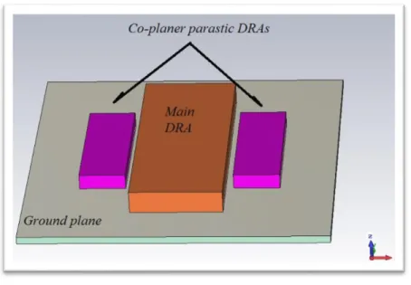
Fig. 2.11 Geometry of co-planar parasitic method.
A three width-band configuration of the DRAs has been pictured the above Fig. where there is a connection between the center DR and the microstrip feed line. The bottom and the above are ground and the substrate placed respectively, with the DR's appearing over the substrate material [31].
The stacked method is, however, more advantageous over co-planar method due to the following drawbacks faced by co-planar.
i. Comparing to a single feed stacked DR method, feeding process in co-planar is complex.
ii. DRA in co-planar needs much effort to align the DRA with the feeding structure. iii. The requirements of the size are higher than the single substrate DR stacked
method.
Considering the previous disadvantages, it is therefore recommended that Stacked Dielectric Resonators Bandwidth Enhancement must be given priority over co-planar.
2.4.5.3 Embedded method
The embedded technique can be used to enhance the bandwidth DRA where DRAs can also be embedded inside one another [31]. Despite its comparison with the stacked method, the co-planar parasitic method has a few shortcomings, such as the use of multiple dielectric constant DRAs, complicate this method as compared to the single dielectric consonant stacked method. Furthermore, the placement of the dielectric resonator of embedded is less flexible when compared to the stacked method. The above shortcomings make the stacked dielectric resonators preferable in term of bandwidth enhancement at millimeter-wave frequencies.
2.5 Dielectric resonator antenna performance
It is the required specifications which are directly related to antenna's application that determines its performance. These applications include frequency of operation, radiation pattern, gain and efficiency, beam-width (main lobes), minor lobes, radiation resistance and overall efficiency, input impedance, bandwidth and polarization (linearly elliptically or circularly)[34]. Besides, features that must be factored include size, structure, feed mechanism, conductors, insulators and weather protection [34].
The performance of the DRA involves a high efficiency, wide bandwidth, no excitation of surface waves, efficiency of high radiation, loss of low dissipation, zero inherent loss of conduction together with consistent radiation pattern, the capability of high power and a rate of high speed, as indicated in the Fig. 2.12.
2.5.1 Radiation Q factor
Some electronic devices have their operations based on resonance principles like resonators, filters, dielectric resonators, and dielectric resonator antennas [35]. The storage and release of the energy typify the resonance principle basis. It is during the object vibration/oscillation when receiving energy from an outside source when the resonance is observed. The type of the energy that is causing an object to oscillate is a function of the object nature with the tendency of freeing the energy that is being received. The relationship describing the release of energy from the object is known as the quality factor represented as Q.
In the device that is designed specifically for resonating or oscillating is assign a given value of Q factor. It is the Q factor that describes the amount of energy that is stored and that relates to the amount of energy emitted. Devices that have a high Q factor emit a little amount of energy, with a lower Q factor releasing much energy. As the Q factor decreases, the energy emitted multiplies.
Q = √𝑉𝑆𝑊𝑅−1
𝑉𝑆𝑊𝑅 (𝐵𝑊) ………. (2-5) [36].
The equation above can act as a good definition of Q factor in terms of the VSWR like VSWR ≤ 2.00, with the bandwidth being (BW). It is clear in this relationship that an increase in BW decreases the value of Q.
2.5.2 Radiation pattern
It is the radiation pattern that describes the signal that is radiated in the form of an electromagnetic field while the antenna gain is defined as a mathematical concept that describes the amount of energy radiated in a specific direction and it is also known as the main lobe as Fig. 2.13 indicates.
The part that best receives and transmits the electromagnetic signal measured on an angular scale is the antenna beam. The minor lobes which include side lobes and back lobes explain the amount of the electromagnetic signal radiated in various direction and propagated with levels that are less as compared to the main lobe [34].
Fig. 2.13 Radiation pattern in 3D and 2D representation.
Radiation efficiency and input impedance are mathematical ideas that regard the signal transition among the -3 dB points, while the bandwidth is the desired frequency range over which the antenna will operate with satisfaction. Moreover, the antenna polarization describes the radiation of the antenna like shape and wave orientation according to its frequency operation [37].
A natural broad radiation pattern without introducing any performance enhancement is a characteristic that makes the DRA is classified as a low-gain antenna [16]. The radiation pattern is influenced by two components namely, the electric field (E) and the magnetic field (H). The E-field is oriented in elevation and the H-field has azimuth orientation [38, 39].
Research reported that a DRA possesses omnidirectional characteristics in the E-field and quasi-omnidirectional in the H component with half-power beam [38].
The cross polarization is one factor that affects radiation pattern and its introduction makes it possible to obtain an improvement in the radiation pattern. Research has shown that when a strip is used in place of feeding mechanism, the level of cross-polarization will decrease, improving the co-polarization radiation pattern [40]. Other shapes and exciting different modes for that shape can be used in changing the radiation pattern, hence, coming up with various types of radiation pattern since every mode will create a new kind of radiation pattern. A gap in the DRA design is therefore revealed to be having no effect on the radiation pattern [41]. Adding the effect of two different modes which are excited in the DRA helps in constructing the radiation pattern [41].
When an antenna design that is composed by a slot and a DRA is used to study the effect of the ground plane in the radiation pattern, the region of the radiation pattern that corresponds to the slot, there is much dramatically effect as a result of changes in the size of the ground plane, as compared to the part of radiation pattern that relates to the DRA [42]. The report revealed that the modification of the radiation pattern is done by making alterations in the slot, more so modification of the slot position and its shape [12]. According to the report, there is a reduced back radiation pattern of DRA when it is placed under the antenna ground plane which can also be referred to as the radial quarter-wavelength metallic annular disc [43]. The same report has also discussed that radiation relies on the mode of excitation together with the level of cross polarization increasing at higher frequencies [26].
The excitation of the TM01ᵟ mode within the DRA helps in obtaining an omnidirectional radiation pattern with ease [43], whose application in the WLAN mobile communication to be appropriate [44].
2.5.3 Input impedance and Bandwidth
The input impedance (Zin) is defined as the impedance at the input of the antenna. It is also the ratio of the voltage and current at its terminal with no load connected [10]. The input impedance of an antenna is ( r ± xj ), and the antenna is said to be resonant if it has real input impedance. In other words, the antenna at the resonant frequency is seen as a resistance, while at other frequencies it is seen as a capacitive or inductive. In some cases, the incident waves that travel from the generator to the antenna, facing mismatching impedance creates some power reflection, which is propagating in the opposite direction.
This reflected value is determined by measuring the ratio between the incident and reflected waves, which is known as the Voltage Standing Wave Ratio (VSWR). If the VSWR = 1:1, which does not happen in practice, that means all incident waves are propagated by the antenna and no reflected waves. The accepted value of VSWR is a subjective value, which means it depends on the system. Some systems accept a VSWR value of 1.5:1 while the accepted standard value is 2:1. The characteristic impedance of the transmission line (Z0) is usually 50Ω.
RF & MW testing and measuring equipment use this reference impedance. To ensure the maximum power transfer, increase the signal to noise ratio, and reduce the source power, the input impedance should be kept as close as possible to the characteristic impedance. If there is an impedance mismatch between the antenna and the transmission line, a part of the transmitted power will be reflected, which might damage the transmitter or the transmission line. Therefore, a matching network circuit has to be designed and connected between the transmission line and the antenna to compensate the mismatching state. A matching network could be a lumped element circuit when the operating frequency is less than 500 MHz, or a distributed element
The bandwidth of the antenna is described as the range of frequencies where the antenna shows the best performance. It is defined in the terms of its frequency limits like the lower and the higher frequencies. The BW attained and the DRA design boundaries are represented by the limit frequencies. It is in a relationship with the associated S11 like IS11I ≤ - 10 dB that the lower and higher frequencies are chosen. The bandwidth is therefore defined in terms of the lower/higher and central frequencies such as 𝑓1, 𝑓2, and 𝑓c respectively as equations (2-6) and (2-7).
𝐵𝑊 =
𝑓2−𝑓1𝑓𝑐 ……… (2-6).
𝑓𝑐 =
𝑓2−𝑓12 ………..……… (2-7).
It is possible that the methods that are used in the assembling processes like the use of adhesive, environment, measurement equipment, and fabrication process can affect the characteristics of low frequency. The adhesive contains a dielectric constant that is capable of influencing the antenna in the electric field. In the case where the adhesive layer contains a different dielectric constant from that of DRA, the operation frequency can be modified up or down. Moreover, the influence of other radiation in the surrounding and the application of measuring equipment that is incorrectly calibrated can degrade the antenna performance.
2.5.4 Directivity and gain
The directivity can be described as the ratio between the radiated power of the antenna in the direction (θ, φ) to the total radiated power in all directions. In other words, the directivity is the ratio of the intensity of the radiation in a given direction to the intensity of the radiation of the reference antenna. The maximum directivity is the ability of the antenna to focus its radiated power in a given direction [46] and it is not affected
by the loss of the antenna. The directivity of the isotropic antenna is unity (0 dB). The antenna directivity can be calculated by using the following formula:
𝐷 =
4 𝜋 𝑈𝑚𝑎𝑥𝑃𝑟𝑎𝑑
=
4 𝜋 𝑈𝑚𝑎𝑥
∫ ∫ 𝑈(𝜃,∅) 𝑠𝑖𝑛𝜃 𝑑𝜃 𝑑∅ ………….……… (2-8).
The antenna directivity has an inverse relationship with the beamwidth. Therefore, directional antennas that have less beamwidth are more directive
The gain of each RF component is the ratio between the input and output power. The antenna gain in a direction (θ, φ) is the ratio of radiated power in (θ, φ) direction to the total power. In other words, the gain is the ratio of the output power radiated by an antenna in a specific direction to the accepted power of a reference antenna. It does not include losses arising from impedance or polarization mismatching; therefore, it measures the performance of the antenna.
𝐺 = 4𝜋
𝑟𝑎𝑑𝑖𝑎𝑡𝑖𝑜𝑛 𝑖𝑛𝑡𝑒𝑛𝑠𝑖𝑡𝑦𝑡𝑜𝑡𝑎𝑙 𝑖𝑛𝑝𝑢𝑡 𝑎𝑐𝑐𝑒𝑝𝑡𝑒𝑑 𝑝𝑜𝑤𝑒𝑟
= 4𝜋
𝑈(𝜃,∅)
𝑃𝑖𝑛 ……… (2-9).
It is important that not to be confused between the directivity and gain as in the reference used in directivity is total radiated power while in gain is the antenna total input power ( accepted from the source). The gain is usually less than the directivity, it also could be equal directivity when the efficiency of the antenna is 100%.
𝐺 = 𝑒
𝑟𝑎𝑑. 𝐷
……….…………. (2-10).We mostly transact with relative gain which is described as the ratio of power gain in a certain direction to the power to the reference antenna gain. It is required that
the power input be equal in both antennas where the reference antenna always a horn, dipole or any other type of antennas with known gain. The reference antenna is, however, lossless isotropic in many cases, thus, the equation presented as
𝐺 =
4𝜋 ∪(𝜃,∅)𝑃𝑖𝑛 (𝑙𝑜𝑠𝑠𝑙𝑒𝑠𝑠 𝑖𝑠𝑜𝑡𝑟𝑜𝑝𝑖𝑐 𝑠𝑜𝑢𝑟𝑐𝑒) ……… (2-11).
Whenever a clear direction not stated, then the power gain will naturally follow the maximum radiation direction.
CHAPTER THREE: DESIGN OF NEW ULTRA-WIDEBAND
DIELECTRIC RESONATOR ANTENNA
This chapter presents a bandwidth enhancement of an aperture coupled stacked dielectric resonator antenna using different position perturbations. The performance of the proposed antenna is compared with the conventional antenna designed without perturbations. The proposed antenna provides not only an ultra-wide matching bandwidth of 5:1 (covering entire C-band to X-Band) but also a higher gain of 9 dBi, which is 2 dBi more than the antenna designed with conventional methods.
3.1 Introduction
In communication systems, the dielectric resonator has more advantages than the microstrip antennas. Some of these advantages are a low loss, particularly at higher frequencies, and a wider bandwidth. The antenna properties of dielectric resonators were discovered by Long and Shen in 1983. By systematic analysis using the mode-merging technique, Young and Long have improved the bandwidth of DRA by varying geometrical parameters [46].
The bandwidth enhancement of the DRA can be achieved using multi-layers with different permittivity. This improved bandwidth of DRAs can increase the communication channels, where a single antenna can cover a large band, which provides a low cost of fabrication. In 1995, a stacked annular ring dielectric resonator (DR) antenna composed of commercially available dielectric resonators and excited by the axis-symmetric coaxial probe was studied computationally using the finite-difference-time-domain (FDTD) method [47]. The DRA bandwidth can also be improved by decreasing the Q factor of the excited DRA by stacking, a compact T-shaped DRA has been provided in 2006 [48]. By placing the dielectric layer of low permittivity below that of a high permittivity, an antenna with a low profile and wider impedance bandwidth has been designed [49]. A hybrid Z-shaped DRA design has been provided with (3.56 GHz-13.1
GHz) bandwidth [50], which is less than the bandwidth obtained from the proposed design.
This work presents a dielectric resonator antenna with ultra-wideband (UWB) characteristics by Position Perturbation in Stacked Dielectric Resonator. The proposed antenna is designed by improving an aperture coupled stacked DRA with the conventional method.
3.2 Ultra-wideband dielectric resonator antennas (two layers of DRs)
An ultra-wideband (UWB) technology was approved by the US Federal Communications Commission to allow an unlicensed band that covers 3.1-10.6 GHz for systems to be able to transmit and receive signals at a very high rate known as nano-seconds by using a very short energy pulse. This new technology has therefore attracted the attention of many researchers alongside engineers because it has wireless characteristics that have a lot of advantages in the UWB world of communication systems like a high-speed rate of data, high precision, lower cost, and lower complexity. A function of the shape and size of the ground plane is the bandwidth and radiation pattern of a UBD.
3.2.1 Aperture Coupled Stacked DRA with Conventional Method (with no offset)
Seeing the effectiveness of the proposed technique requires that the conventional aperture coupled without perturbations is used in designing an antenna, as shown in the figure below. There are two resonators in the stacked DRA; namely, D2 (larger size) and D1 (smaller size) that also consist of a relative permittivity of 6.15 and 9.8, respectively. A microstrip line feeds the antenna a rectangular made of GND coupling the energy to the radiator. Roger 5880 LZ substrate with permittivity of 1.96, and a thickness of 1.27 mm. is used in printing both TL and the aperture antenna. Various dimensions are used in the design, as shown in Fig. 3.1.
Fig. 3.1 The basic structure of an aperture coupled stacked DRA, (a) side view, (b) a perspective view, (c) back view.
Table 3.1 shows the value of antenna parameters.
Table 3.1 The dimensions of the proposed antenna.
Parameter W L W1 L1 W2 L2
Value (mm) 108 90 25 18 49.5 65
Parameter Wf Lf Ws Ls h h1=h2 Value (mm) 4.25 37 27 2.43 1.27 5.08
3.2.2 Proposed Aperture Coupled DRA with Improved Performance
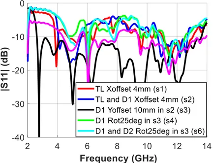
This section illustrates how the proposed perturbation technique enhances the bandwidth of the conventional antenna. The effect of location offset and the rotation are considered in the perturbation. This perturbation technique is implemented in different steps and labeled “S1 to S6” as:
(1) TL shifted along X-axis 4 mm (S1). (2) D1 4 mm offset along X-axis (S2).
(3) The D1 offset of 10 mm along Y-axis from its last position (S3). (4) D1 clockwise rotation of 25 degrees (S4).
(5) D2 clockwise rotation of 25 degrees (S5).
(6) Both D1&D2 clockwise rotation of 25 degrees (S6).
The effect of the proposed technique on the antenna performance is discussed in Section 3.2.4.
3.2.3 Parametric study
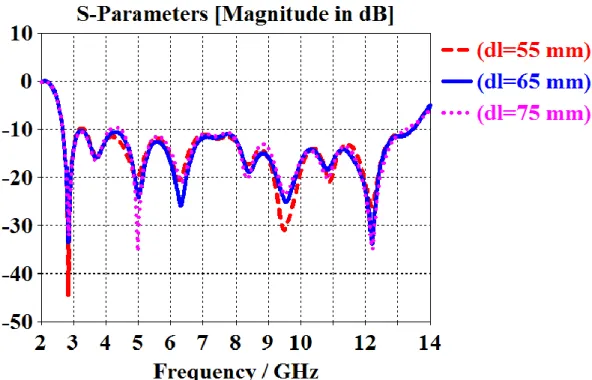
The position of the small dielectric resonator has a big influence on the matching bandwidth as well as the dimensions of DR2 because it controls the physical length of the driven element. Therefore, the position of the DR1, as well as the length and width of the DR2, are precisely chosen to accomplish the required bandwidth.
Several parametric studies were carried out to determine the perfect position of the DR1 and the dimensions of the DR2, as shown in Figs. 3.2, 3.3, and 3.4, respectively. It can be observed that when the DR1 is shifted 4 mm along X-axis (xx), the proposed antenna bandwidth becomes continued. On the other hand, the proposed antenna has the best bandwidth when the length (dl2) and width (dw2) of DR2 are 65 mm, 50 mm, respectively.
Fig. 3.2 The effect of DR1 shifting along X-axis (xx).
Fig. 3.4 The effect of the width of DR2.
3.2.4 Simulation results and discussion
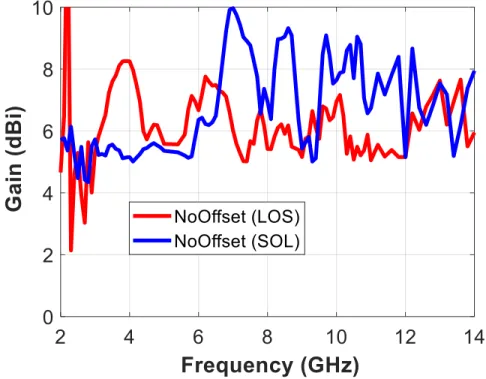
The performance of the conventional antenna is analyzed in terms of the reflection coefficient, realized gain, and the radiation pattern in both E-and H-planes. Figs. (3.5, 3.6, 3.7 and 3.8) show the performance of a stacked DRA antenna designed with the conventional aperture coupled method without perturbation (referenced performance). It is clear from these results shown in Fig. 3.2 that in both LOS and SOL environment of the resonators, the accumulative matching bandwidth is less than 2 GHz in the whole band, while the average gain almost remains between 7 to 8 dBi.
Fig. 3.6 shows the simulation results of the conventional antenna frequency vs gain.
Fig. 3.5 The simulation results of the conventional antenna, frequency vs. reflection coefficient magnitude.
Fig. 3.7 The simulation results of the conventional antenna E-plane radiation patterns vs. frequency.
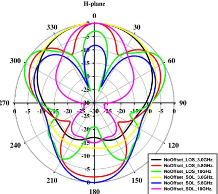
Fig. 3.8 The simulation results of the conventional antenna H-plane radiation patterns vs. frequency.
E-plane 0 30 60 90 120 150 180 210 240 270 300 330 -30 -25 -20 -15 -10 -5 0 -30 -25 -20 -15 -10 -5 0 -30 -25 -20 -15 -10 -5 0 -30 -25 -20 -15 -10 -5 0 NoOffset_LOS_3.0GHz. NoOffset_LOS_5.8GHz. NoOffset_LOS_10GHz NoOffset_SOL_3.0GHz. NoOffset_SOL_5.8GHz NoOffset_SOL_10GHz. H-plane 0 30 60 90 120 150 180 210 240 270 300 330 -30 -25 -20 -15 -10 -5 0 -30 -25 -20 -15 -10 -5 0 -30 -25 -20 -15 -10 -5 0 -30 -25 -20 -15 -10 -5 0 NoOffset_LOS_3.0GHz. NoOffset_LOS_5.8GHz. NoOffset_LOS_10GHz NoOffset_SOL_3.0GHz. NoOffset_SOL_5.8GHz NoOffset_SOL_10GHz.
Figs. 3.7 and 3.8 show the radiation patterns in both E- and H-planes at different frequencies (3.0 GHz, 5.8 GHz, and 10.0 GHz), respectively, which exhibit that the antenna radiation is good at the lower frequency, while as the frequency increases, the radiation is heading for the worst. The pattern degrades in both E- and H- planes.
Fig. 3.9 The simulation results of the proposed antenna with Perturbations, frequency vs. reflection coefficient magnitude.
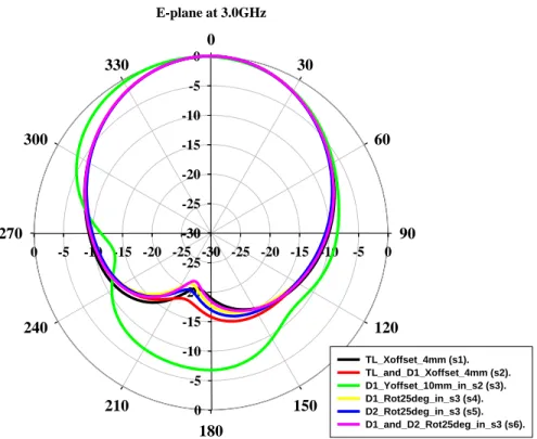
Similarly, Figs. (3.9, 3.10, 3.11 and 3.12) show the performance of the proposed antenna in terms of same steps discussed in Section (2). It is clear from these results that using the proposed perturbation technique results in more than 5:1 matching bandwidth ratio, while the highest gain is 9 dBi, the average gain remains little higher than the conventional case. The radiation pattern in both E- and H-planes are improved as shown in Figs. 3.11 and 3.12 show.
To reduce a crowdedness of curves in the radiation patterns, the radiation patterns at 3 GHz is shown in both planes. The performance of the proposed antenna versus the conventional is summarized in Table 3.2.
Table 3.2 Performance Comparison between two cases, conventional stacked DRA, and the proposed stacked DRA.
Techniques IS11I Avg. BW Max. Gain
Proposed Perturbations (with offsets and rotations) 2.7-13.6 GHz 9 dBi Conventional No perturbations (without offset and
rotations)
Fig. 3.11 The simulation results of the proposed antenna with perturbations for E-plane radiation patterns at 3 GHz.
Fig. 3.12 The simulation results of the proposed antenna with
E-plane at 3.0GHz 0 30 60 90 120 150 180 210 240 270 300 330 -30 -25 -20 -15 -10 -5 0 -30 -25 -20 -15 -10 -5 0 -30 -25 -20 -15 -10 -5 0 -30 -25 -20 -15 -10 -5 0 TL_Xoffset_4mm (s1). TL_and_D1_Xoffset_4mm (s2). D1_Yoffset_10mm_in_s2 (s3). D1_Rot25deg_in_s3 (s4). D2_Rot25deg_in_s3 (s5). D1_and_D2_Rot25deg_in_s3 (s6). H-plane at 3.0GHz 0 30 60 90 120 150 180 210 240 270 300 330 -30 -25 -20 -15 -10 -5 0 -30 -25 -20 -15 -10 -5 0 -30 -25 -20 -15 -10 -5 0 -30 -25 -20 -15 -10 -5 0 TL_Xoffset_4mm (s1). TL_and_D1_Xoffset_4mm (s2). D1_Yoffset_10mm_in_s2 (s3). D1_Rot25deg_in_s3 (s4). D2_Rot25deg_in_s3 (s5). D1_and_D2_Rot25deg_in_s3 (s6).
![Fig. 1.1: DRA as an alternative to traditional low gain antenna elements [3].](https://thumb-eu.123doks.com/thumbv2/123doknet/5005208.124775/18.918.118.811.121.379/fig-dra-alternative-traditional-low-gain-antenna-elements.webp)
![Fig. 2.1 Basic operation of transmitting and receive antennas [8].](https://thumb-eu.123doks.com/thumbv2/123doknet/5005208.124775/21.918.198.720.657.881/fig-basic-operation-transmitting-receive-antennas.webp)
![Fig. 2.3 Techniques for bandwidth enhancement [13].](https://thumb-eu.123doks.com/thumbv2/123doknet/5005208.124775/23.918.159.808.508.815/fig-techniques-for-bandwidth-enhancement.webp)