HAL Id: hal-01083919
https://hal.archives-ouvertes.fr/hal-01083919
Submitted on 18 Nov 2014
HAL is a multi-disciplinary open access
archive for the deposit and dissemination of
sci-entific research documents, whether they are
pub-lished or not. The documents may come from
teaching and research institutions in France or
abroad, or from public or private research centers.
L’archive ouverte pluridisciplinaire HAL, est
destinée au dépôt et à la diffusion de documents
scientifiques de niveau recherche, publiés ou non,
émanant des établissements d’enseignement et de
recherche français ou étrangers, des laboratoires
publics ou privés.
Bandwidth behavior of miniature cavity antennas
Mario Martinis, Ronan Sauleau, Kouroch Mahdjoubi, Sylvain Collardey, Loic
Bernard
To cite this version:
Mario Martinis, Ronan Sauleau, Kouroch Mahdjoubi, Sylvain Collardey, Loic Bernard. Bandwidth
behavior of miniature cavity antennas. Journées JCGE’2014 - SEEDS, Jun 2014, Saint-Louis, France.
�hal-01083919�
Bandwidth behavior of miniature cavity
antennas
Mario Martinis
1,2, Kouroch Mahdjoubi
1, Ronan Sauleau
1, Sylvain Collardey
1, Loic Bernard
2 1:
Institut d'Electronique et des Télécommunications de Rennes, 35042 Rennes, France,
2
: Institut franco-allemand de recherche pour la défense, 68300 Saint-Louis, France
ABSTRACT - For mechanical or thermal performance or for integration into a small part of a platform it is sometimes required to place an antenna into a small metallic cavity. The main consequence is the reduction of the antenna bandwidth. The objective of this study is to investigate the maximum possible bandwidth depending on the cavity height at a fixed frequency (2.3 GH)z. We compare simple cavity antennas to cavities with a patch at the aperture and to cavities with a proposed reactive impedance surface (RIS) replacing the patch. For this study we considered square cavities of sizes 32mm (0.246λ0), 40mm (0.3λ0) and 48mm (0.37λ0) and the effect of different relative permittivity values inside, namely 3.66, 6.15 and 10.2. For each height, up to a maximum height where matching is still possible, patch antennas were optimized to have minimum of S11 at 2.3 GHz equal to -33dB. Numerical results for patch antennas are compared to analytical predictions for a simple cavity antenna of the same size excited only by the TE mode and to cavities with a RIS at the aperture. Patch antennas show unexpected dependence of bandwidth on permittivity when cavity height is approaching the guided wavelength of the dominant TE mode in the cavity. Maximum bandwidth is observed to be the highest when a RIS is used at the aperture.
1. Introduction
Benefits of cavity-enclosed microstrip patch antennas are a miniature configuration, isolation from surroundings, reduced backward radiation, and importantly, reduction of surface waves which decrease efficiency, thus, a cavity allows the substrate thickness to be increased without negative effects [1-4]. However, the main drawback of placing an antenna inside a cavity is bandwidth reduction. For simple cavity antennas it was shown that bandwidth depends directly the aperture size of the radiator and decreases very rapidly when decreasing the aperture size [5-6]. A very small cavity environment also eliminates the possibility of adding parasitic elements because in a small volume two resonators become tightly coupled and a bandwidth broadening effect is impossible. Thus we decided to study a single resonance antenna in a small cavity and conditions to achieve maximum possible bandwidth.
2.
Antenna structure
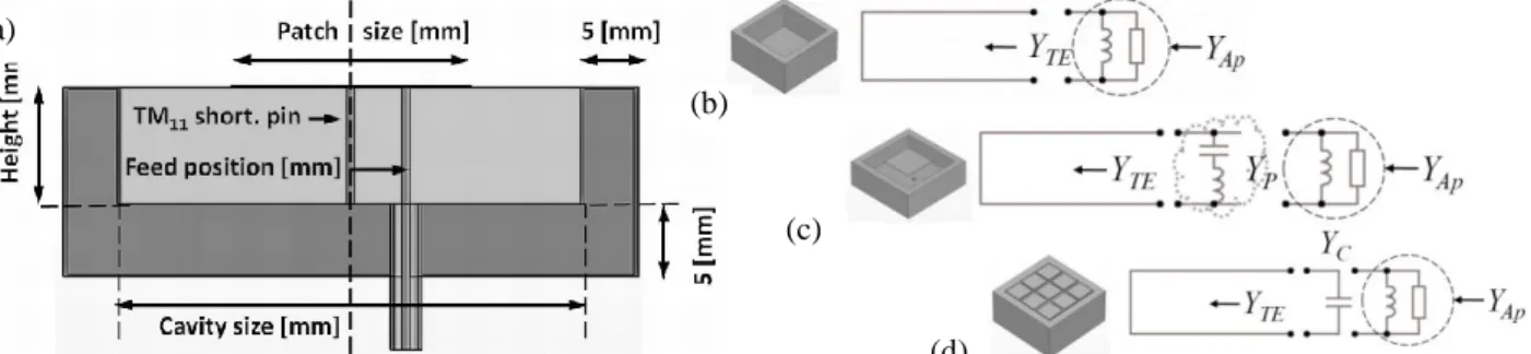
The cavity (Fig. 1(a)) was designed with a wall thickness of 5mm on the sides and bottom and is surrounded by open space. Excitation is done trough a coaxial cable and a probe inside the cavity. Optimization was performed for 3 permittivities (3.66, 6.15 and 10.2), 3 cavity sizes (32, 40 and 48mm) and discrete increments of height (Δh = 1mm) until matching was possible. The variables for optimizing the resonance at 2.3 GHz were patch size and feed position. In the case of a large cavity it was necessary to add a wire in the center of the cavity and connect it to the patch to short out the TM11 waveguide mode that can be excited in thick substrates.
Figure 1 : (a) Design and dimensions of a square cavity with a patch. (b) transmission line model of a simple cavity antenna (c) model of a cavity with a patch at the aperture. (d) model with a capacitor corresponding to a reactive impedance surface at the aperture.
3.
Bandwidth behavior of microstrip antennas in a small cavity
Bandwidth was analyzed in three steps. First, without the patch, the cavity part of the antenna behaves as a short waveguide that is open ended to free space. It can be modeled with a transmission line having a short circuit at one end and a load at the aperture, as in Fig 1(b). We assume only the dominant TE01 in the waveguide which is a good approximation, and
(a)
(b)
(c)
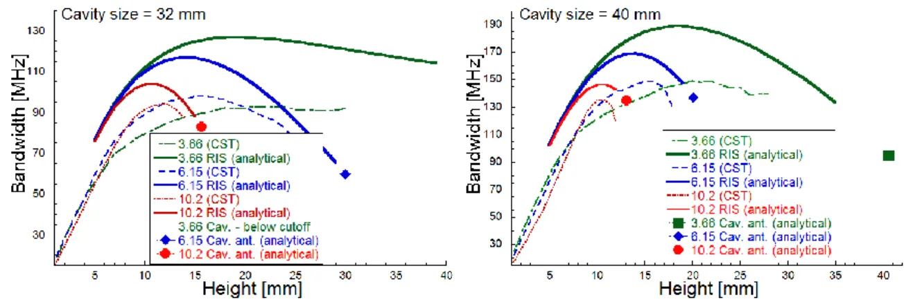
the aperture admittance for that specific mode is known analytically [3] (or is calculated numerically for a finite cavity in our case with commercial software [8] using a waveguide port inside the cavity). A cavity antenna resonates at one specific height as is indicated by points on graphs in Fig 2. (a) and (b).
Second, with a square patch at the aperture, the cavity can be made resonant at any height by adjusting the patch size and feed position. Simulation results (performed with commercial software CST [8]) for patch antennas are shown by dashed curves in Fig 2. (a) and (b). They show unexpected behavior for thick cavities i.e. a height for which there is no dependence on permittivity (≈8mm) and above it, an inversion of bandwidth dependence on permittivity. A model for such antenna is suggested in Fig 1(c). However, this model cannot be analyzed analytically for it has too many degrees of freedom.
Third, a simplified model involving only an additional capacitor at the aperture is introduced and analyzed analytically. The model in Fig. 1.(d) predicts different bandwidth behavior compared to patch antennas i.e. no inversion of bandwidth dependence on permittivity and more importantly, higher maximum bandwidth. A new structure composed of small patches, shown in Fig1(d), is proposed based on this model. This structure is similar to the structure introduced in [7] and can be called a reactive impedance surface (RIS). Fig. 2 is showing analytical results obtained with this model on top of simulation results for patch antennas. Simulations of cavities designed with a RIS at the aperture were done for several heights and cavity sizes and confirm the predictions of the simplified model. This new design shows bandwidth improvement compared to classical patch design in a cavity is indeed possible. Further confirmation by detailed numerical simulations and manufacturing of prototypes is a subject of our current and future work.
Figure 2 Simulation results for patch antennas (dashed), analytical results for a cavity with a RIS at aperture (full lines) and analytical results for cavity antennas (points). (a) Rectangular cavity of size 32x32mm and (b) Rectangular cavity of size 40x40mm.
4. Conclusion
For classical patch antennas larger substrate permittivity leads to lower bandwidth, however, inside a cavity acting as a short waveguide, this dependence can be reversed for a range of larger heights where best performance can be achieved with highest permittivity. Compared to a simple cavity antenna with nothing at the aperture, patch antennas in the same type of the cavity can have larger bandwidth and exhibit a bandwidth maximum at a lower height than the operational height of the simple cavity antenna. However, even larger bandwidth can be achieved by using a special structure at the aperture that represents a capacitor in our model. Such a structure can be designed using small periodic metallic patches similarly to the reactive impedance surfaces known in the metamaterial field of research.
Références
[1] N. C. Karmakar “Investigations Into a Cavity-Backed Circular-Patch Antenna” IEEE Trans. on Ant. and Propag., vol. 50, no. 12, Dec. 2002
[2] J.T. Aberle: “On the use of metallized cavities backing microstrip antennas”, Ant. and Propag. Society International Symposium, June 1991.
[3] F. Zavosh and J. T. Aberle:"Improving the Performance of Microstrip-Patch Antennas", IEEE Ant. and Prop. Magazine, Vol. 38, No. 4,August 1996
[4] F. Zavosh and J. T. Aberle: „Single and Stacked Circular Microstrip Patch Antennas Backed by a Circular Cavity“, IEEE Transactions On Antennas And Propagation. VOL. 43, NO. 7, July 1995
[5] M. H. Cohen “The Normal Modes of Cavity Antennas” Ph.D. Thesis, Antenna Laboratory, Department of Electrical Engineering, Ohio State University Research Foundation, 1952
[6] M. H. Cohen: “On the Band Width of Cavity Antennas”, Journal of Applied Physics, Vol.25, Issue 5, May 1954. [7] H. Mosallaei, K. Sarabandi “Antenna Miniaturization and Bandwidth Enhancement Using a Reactive Impedance
Substrate”, IEEE 2004.