Ability
of
a
Robot
to
Travel
Through
ree Work
Space
in
an
Environment
with Obstacles
Philippe
Wenger
Patrick Chedmail
Laboratoire d’Automatique de Nantes
Ecole Nationale Supérieure de
Mécanique
Nantes, FranceAbstract
This article presents a new geometric
analysis of the free
work spaceof a
robot among obstacles.The free
work space(FW)
isdefined
as the setof positions
and orientations thatthe robot’s end
effector
can reach,according
to the jointlimits and the various obstacles
lying
in the environment.The aim is to give
global descriptions of the
robot’sability
tomove in the
operational
space(which
coincides withCarte-sian space when
only
position coordinates arespecified).
The main contributionof
this work is the characterizationof the effects of obstacles
on the work space geometry, as wellas on its
topology.
Theability of a
robot tomove freely
in itswork space
(called
the"moveability")
isdifficult
to describe and needs stringentformalizations.
The conceptof
move-ability
is introducedthrough
various properties and theircor-responding
necessary andsufficient
conditions. Using aCon-structive Solid
Geometry
(CSG)Computer-Aided
Design(CAD) description of robots
and obstacles and an octreemodel
of the
FW, these properties permit characterizationof
selectedmoveability
areas in the FW, where,for
instance,any n points can be linked
together
or where any continuoustrajectory can be achieved without
changing configuration.
This new
global description
isof great
interest for
the userof
CAD systems whendesigning
robotic cells.1.
Introduction
Automatic
Design
orComputer
AidedDesign
ofro-botic cells is
actually
animportant challenge
inin-dustry
and involves several difficultgeometric
prob-lems :
. the choice of a
robot;
thedifficulty
is to find themorphology (type
and number ofjoints,
length
oflinks, ...)
that is best suited to thefamily
of tasks to be achieved.. the
geometric
layout
of thecell;
one has toposi-tion the
robot(s)
and the other components of the cell in such a way that the robot is able to workconveniently
in the environment(accessibility
of thespecified
work areas, as well asmobility
inthem,
should beensured).
. Collision-free
paths planning;
theproblem
is tofind a continuous
path
among obstacles betweenone
specified
location to another.This third
problem
has drawn the interest of manyauthors,
and its theoretical solution is now well known(Schwartz
and Sharir1982; Brady
et al.1982; Canny
and Reif1987).
Thetechniques
are various: forin-stance, the local
approaches
withpotential
methods(Khatib
1985;
Koditschek1987)
or theglobal
onesbased on the
configuration
spaceanalysis
andusing
cell
decomposition
(Faverjon
1984;
Brooks1983a,b;
Lozano-P6rez1986)
or retractiontechniques
such asstratified sets
(Canny 1987)
and Voronoidiagrams
(O’Dunlaing
et al.1984; Canny
and Donald1988).
These studies havealready
given
rise tooperational
systems
(Lozano-P6rez
et al.1987).
On the other
hand,
the first twoproblems
have notbeen so
extensively
studied. Softwares of currentro-botics
computer-aided design
(CAD)
systems(such
asROBCAD from
Teknomatix,
MACAUTO fromMcDonnel-Douglas,
CATIA from DassaultSystem,
orROBOT PLUS from
Computervision)
allrequire
theaction of a human operator who selects the
right
solu-tion,
validates thechoices,
and modifies theparame-ters if necessary
(Bernard 1984;
Dombre et al.1986;
Deligneres
1987).
This article deals with these first twoproblems.
For both ofthem,
characterization andanalysis
of the free work space are well-suited aids.is the space of
positions
and orientations of the end effectoraccording
to thejoint
limits and the variousobstacles.
Concerning
the firstproblem,
criteria suchas
volume, connectedness,
compactness of the workspace, or
dexterity
in it are very convenient for theoptimization
of the robot’smorphology,
asthey
give
agood
evaluation of thegeometric
performances
of themanipulator (Vijaykumar
et al.1986;
Lenarcic et al.1988).
Apossible
solution to the secondproblem
is the characterization of selectedregions
of&dquo;moveabil-ity&dquo;
in the work space. The aim is then to ensure thefeasibility
of tasks defined as areas to befreely
reached(Deligneres
1987) and/or
to be &dquo;travelledthrough&dquo;
ina certain sense
by
the robot(e.g.,
areas of continuouswelding
orpainting).
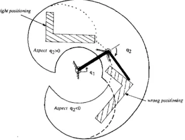
InFigure
1,
thepiece
cannot beplaced anywhere
in the free work space; it must be enclosed in aregion
reachable fromconfigurations
q2 > 0 or q2 < 0
separately.
The
goal
of ourstudy
is togive
aglobal
description
of the obstacles in the
operational
space(space
of posi-tions and orientations of the endeffector;
this space coincides with the Cartesian space whenonly position
coordinates arespecified).
This is achievedthrough
geometric
andtopologic analysis
of the FW. This newdescription
is of great interest for thedesigner
ofro-botic cells.
A lot of work has
already
dealt with work spaceanalysis. Typical geometric
characterizations of a work space are:1. Its well-known
projections
in the Cartesian space:&dquo;reachable work
space&dquo;
(projection
of the wholeFig. 1. The task to be achieved is continuous
welding of a
piece. The piece must be
carefully placed
in the work space toavoid
configuration changing during
the operation. The endeffector
must remain in the same aspect.work
space)
and &dquo;dextrous workspace&dquo;
(projec-tion of the work space part where every orienta-tion of the end effector ispossible) (Kumar
and Waldron1981).
2. The
analysis
of holes and voids in the work space(Gupta
and Roth1982).
3. The
approach angles
andlengths (Hansen
et al.1983).
4. Work area
analysis
(Yang
and Chiueh1986).
5. Characterization of the so-called
&dquo;aspects&dquo; (set
ofpositions
and/or
orientations reachable undergiven configurations)
(Borrel 1986).
6. &dquo;Well-connectedness&dquo;
(ability
to move betweenany two
points
in the work space withoutchang-ing
configuration)
(Paden
andSastry 1988).
However,
none of these take into account the effectsof obstacles. The
proximity
of obstacles notonly
modi-fies theshape
of the work space, but also reduces themoveability
of the robot withinit,
as hasalready
beenshown in Chedmail and
Wenger (1987; 1988). Figure
~A shows a verysimple example
where the FW isconnected but does not allow the robot to travel
through
it. InFigure
2B,
themobility
between anytwo
points
within the FW isensured,
but notnecessar-ily
along
agiven
continuoustrajectory.
In this
article,
we propose fivestringent
character-izations of the
moveability
in the FW for a robotamong obstacles. We attach five necessary and
suffi-cient conditions to these characterizations. These
con-ditions are tested
using
a constructive solid geometry(CSG)
CADtechnique
(Martin
et al.1985)
and anoctree model of the FW.
Finally,
analgorithm
isde-scribed to check the various
properties,
and results arepresented.
2.
Definitions
We
give
in this section some definitions beforepro-ceeding
further.Let a robot - called
R OBO T(q) -be
definedby
its ~tdegrees
of freedom:ROBOT(q),
enclosed in1~3,
is defined as a set of nsolids,
as inWenger
(1985)
and Yu and Khalil(1986).
Let an environment with obstacles be defined
by
Ob = set of the
physical
obstacles of theenvironment,
enclosed in R3
Let f:
f~8~ ~ Rm be thegeometric
operator of therobot
(Khalil
andKJeinfinger
1986),
where m is the number ofoperational
coordinates of the end effectorFig. 2A, A two-DOF
plannar
linkage
with one circular obsta-cle and -120° ::::; q, ::::; 1200,- 1800 ::::; q2 ::::; 1800.The free
work space is connected; however, the robot cannot travel
through
it but canonly
moveseparately
within part 1 or part2B, A
two-DOF plannar
linkage
with onerectangular
obsta-cle and - 90° ~ q, - 90°,-100° - q2 -- 1200. The robot canjoin any two points in its
free
work space but notalong
anytrajectory
(the
given continuous trajectory isunfeasible;
point X, can be reachedonly
in aspect 1 becauseof the
joint limits, and pointX2
can be reachedonly
in aspect 2 becauseof the
obstacle).
Let .9 =
(q
E R&dquo;~/1,
CJl&dquo;~ ~
~’i ~~’imin)
be thecon-figuration
space,according
to thejoint
limits. LetQf be
theconfiguration
collision-free space ofROBOT(q):
Let
Wf be
the FW ofROBOT(q).
It is theimage
ofQf under
thegeometric
operator:
The
free
work space is the space ofpositions
and ori-entations of the end effectoraccording
to thejoint
limits and the various obstacles in the environment. Apoint
X inWf is
a vector of moperational
coordinates.We suppose that there are N connected components
of
Qf.
We shall denote them as:The
following
relations hold:not connected. Then:
d i E I:
Wf = f(Qf )
is theimage
ofQfi
under thegeometric
operator.The
following
relation holds:Define: The aspects are defined as in Borrel
(1986);
an aspect is a
subspace
A enclosed inQf such
that: l. A isconnected,
2. V q E
A;
the determinant of any m X m matrixextracted from the Jacobian matrix J is not
equal
to zero, except if this minor isequal
to zeroev-erywhere
in 2. The components of J are:where qj
is thejth
componentof q,
and x; is theith
operational
coordinate of X= f (q)
(1
_ i ~ mand 1
; j =
n.).
The number of aspects is finite.
(14~),zj
is apartition
of 2.
3. Characterization of
the
Robot’s
Ability
toMove
Through
Wf
We expose in this section the five characterizations of
the
moveability
in the FW of arobot,
and theircorre-sponding
necessary and sufficient conditions.3.1. First
Characterization
andCorresponding
Necessary
andSufficient
ConditionThe FW can be travelled
through
by
the robot in the sense ofP, if, by definition,
any twopoints
inWf can
be
joined
by
the end effector. This means that for anytwo
points
in theFW,
a connected component of theconfiguration
collision-free space exists such that itsimage
under f contains
both of thesepoints:
Note: This first property can be
expressed
in a moresuccinct way:
Wf satisfies P,
if andonly
ifWf is
connected,
and there exists afamily (I, , 1~2,
... ,Ip) _
(Iklk c
K)
of subsets of I such that:(See
the demonstration inAppendix
A.)
Example:
IfQf is
composed
of three connectedcomponents, the
following
relations hold:Assume:
and
Then
Wf satisfies
P,
(Fig.
3).
COROLLARY 1
Wfp
cWf satisfies
thegeneralized
property
P1 ( Wfp)
where:if and
only
if there exists afamily
{I~,
12,
... ,Ip~ _
(Iklk
EK)
of subsets of I such that:which can be written in the
following
more succinctway:
Note: Because any subset of set
satisfying P, { Wfp)
also satisfiesP, (Wfp),
such subsets are notnecessarily
connected.
Fig. 3. A case where
the free
work space can be traveledthrough
in the senseof P, .
Definition I
The maximal parts
Wfp
ofWf satisfying Pi
(
Wfp)
aredefined as follows:
There exists a
family ~I~, I2, . _ . ,
Ip} _
(Iklk
EK)
of subsets of I such that:
Note 1:
Any
partsatisfying
PI(Wfp)
is enclosed in sucha maximal part. The converse
being
true, it isinterest-ing
to find the maximal partssatisfying
P, (see
Fig.
4A;
in the case whereCard(I)
=3,
there are fourmax-imal parts
satisfying
P1 ( Wfp)).
Note 2: The
properties P,
andP1(Wfp)
do not take into account initial and finalconfigurations.
More-over, every
trajectory
in the FW betweenX1
andX2
isnot
necessarily
achievable. That iswhy
we willcom-plete
this definition in thefollowing
property;then,
in the next twoproperties,
we willsuccessively
take intoaccount the
configuration
atpoint
X, (or X2 )
and thenat
points
X1 and X2 ; finally,
we will propose aprop-erty of
mobility
along
any continuoustrajectory
through
the FW.3.2. Second
Definition (Pz)
andCorresponding
Necessary
andSu,fj~cient
ConditionThe FW can be traveled
through by
the robot in thesense
of P2
if, by definition,
every discretetrajectory
Td
in
Wf is
achievable,
which means:Fig. 4. The
different
maximal partsof the free
work spacesatisfying
(A) P, (Wfp),P2(Wfp)
(B),P3(Wfp)
(C) andP¢(Wfp)
(D) when theconfiguration collision-free
space hasthree connected components.
Note: A discrete
trajectory
is anarranged
sequence ofpoints.
Wf satisfies
P2
if andonly
if(See
the demonstration inAppendix B.)
COROLLARY 2
Wfp
cWf satisfies
thegeneralized
property
P2( Wfp),
where:(PZ( W.~P))
V Td discrete trajectory in Wfp, 3 i E I such that Td C W£ n Wfp
if and
only
ifDefinition
2The maximal parts
Wfp satisfying P2(Wfp)
are defined as follows:(see Fig.
4B;
in the case whereCard(I)
=3,
there arethree maximal parts
satisfying
PZ(Wfp)).
3.3. Third
Characterization
andCorresponding
Necessary
andSu~cient.Condition
The FW can be traveled
through
by
the robot in thesense of
P3 if,
by definition,
any twopoints
inWf can
bejoined
by
the endeffector,
whatever the initial or(exclusive or)
finalconfiguration:
Note: This third
property
can beexpressed
in a moresuccinct way:
Wf satisfies P3
if andonly
if:(See
the demonstration inAppendix C.)
then
Wfp
satisfies thegeneralized
propertyP3(Wfp),
where:if and
only
if:for some sets I’ of indices in I.
(See
the demonstrationin
Appendix D.)
Definition 3
The maximal parts
Wfp satisfying
P~,(Wfp)
are defined as follows:for any subsets I’ of I such that
Wfp
isnonempty.
(See
Fig.
4C;
whenCard(I)
=3,
there are seven maximal3.4. Fourth
Characterization
andCorresponding
Necessary
andSu~tcient
ConditionThe FW can be traveled
through by
the robot in thesense of
P4 if, by definition,
any twopoints
inWf can
bejoined
by
the endeffector,
whatever the initial andfinal
configurations:
Wf satisfies P4
if andonly
ifQf is
connected(the proof
isobvious).
COROLLARY 4 Let
Qfp
be defined as inprevious
corollary
3.Wfp
cWf satisfies
thegeneralized
propertyP4( Wfp)
where:if and
only
if:(See
the demonstration inAppendix
E.)
Definition 4
The maximal parts
Wfp
satisfying
P4 Wfp)
are defined as follows:(See Fig.
4D;
in the case whereCard(I)
=3,
there arethree maximal parts
satisfying
P4(Wfp).)
Note:
Properties P4
up toP,
characterize fourin-creasing
levelsdescribing point-to-point
motions in theFW of a robot:
3.5.
Fifth
Characterization
andCorresponding
Necessary
andSuJ,~icient
ConditionThis fifth property will concern
only
nonredundantrobots,
for which thegeometric
operator isbijective
onthe aspects.
The FW can be traveled
through by
a nonredundantrobot in the sense of
Pg
if, by definition,
any twopoints
inWf can
bejoined
with any continuoustrajec-tory
T~
withoutchanging configuration
andregardless
of the initial or final
configuration.
For
any j
in J(set
describing
the aspectsAj),
define thesingle
partition
(Aik )kElj
of the aspectsA j
incon-nected components
Ajk
as:We note,
for j
E J and k EIj:
is the
image under f of
the connected component k of theaspect j
in theoperational
space.Similarly,
we note,for j
E J:is the
image
of theaspect j
in theoperational
space.According
to the results obtainedby
Borrel(1986)
andgeneralizing
them in the case of environmentswith
obstacles,
this fifth property can beexpressed
as:Wf satisfies
property
Ps
if andonly
ifThe
proof
isquite
analogous
to that of theorem 3. COROLLARY 5 LetQjp
be defined as inprevious
corollary
3. ThenWfp
CWf satisfies
the propertyPs(Wfp),
where:if and
only
if:where J’ is a set of indices in
J, and,
forany j
inJ’,
I’( j )
is a set of indices inI(j).
The
proof
isquite analogous
to that ofcorollary
3.Definition
5The maximal parts
Wfp satisfying
PS ( Wfp)
are defined as the connected components of:4.
Algorithmic
Analysis
of
the
Robot’s
Ability
toTravel
Through
Wf
Let
Wfp
be enclosed in(or
equal
to)
Wf.
There existsan
infinity
of partsWfp
thatverify
P, ( Wfp)
orP2 ( Wfp)
(any
subset of anyWfi,
forinstance).
Thefollowing
algorithm
tests theproperties
P~ , P2 , P3 ,
andP4
forWf
and leads to all the maximal partsWfp satisfying
P, (Wfp) or P2(WfP).
The robot and its environment are modeled
using
aCSG CAD
technique.
It makes itpossible
toperform
collision detection between the robot and its
1. Determination of
I,
(<2/,),e~ {Wf,-}lEr, Wf, Qf: in
the case where n - 3 and 7~ ~3,
we use anoc-tree
(octal tree)
description
of these spaces in asimilar way as in
Faverjon (1986). If r~ - 3,
thewrist may be modeled
by
acircumscribing
sphere.
The FW and theconfiguration
collision-free space are obtained
by sweeping
theconfigu-ration
space 2 according
to thejoint
limits.Col-lision detection is
performed using
an efficientalgorithm
described in Yu(1987).
Finally,
analy-sis of the connected components of
Qf,
asde-scribed in Samet
(1979)
and Chedmail andWenger
( 1988)
leads to I and to the octree defini-tion ofQfi
andW¡;.
2. Verification of the property
P4: If Card(I)
=1,
then
Qf is
connected;
thereforeP, (and
soP1, P2 ,
P3 )
is true forWf;
end of thealgorithm.
else
3. Verification of the property
P3 : If d i E I, W£
=Wf,
thenP3
is true forWf;
end of thealgorithm.
else4. Verification of the property
P2
and determinationof the maximal
Wfp satisfying P2( Wfp):
If ~ i E I,
Wf
= Wf,
thePZ
is true forWf;
the maximalparts
satisfying
P2(Wfp)
are theWf ;
end of thealgorithm.
else
5. Verification of the property
P,
and determinationof the maximal
Wfp satisfying
only P,
( Wfp):
a. Enumerate all
possible
families of nonemptysubsets of I. For each such
family,
say{Ik/kEK},
determineNote: the deternnination of B is
performed
using
the octree model with verysimple
and fast booleanoperations.
b. If B is nonempty, then it satisfies
P~ ( Wfp);
goto 5a.
End of the
algorithm.
We can make the
following
remarksconcerning
thepart 5 of the
algorithm:
Note 1: It is
possible
toconsiderably
reduce the number of cases as a lot of them do not have to bestudied:
1.
Card(Ik)
= 1. Then the element i ofIk
satisfiesWf
=Wfp,
already
seen2. There
exists jo
such that V k EK, jo c Ik.
ThenWfp
CW, f~
andWfp
is not maximal. Inparticu-lar,
if Card(K)
= 1: there exists i in I such thatWfp
CWf ,
andWfp
is not maximal.3. A great number of sequences
{Ik}kEK
do not haveto be tested as
they
generate nonmaximal parts.For
instance,
in the case where N =4,
these-quence
{( 1,
2),
(2, 3), (1, 3,
4)}
does not have tobe
studied,
because thesubspace generated by
it is enclosed in the maximalWfp
generated by
thesequence
f ( 1, 2), (2, 3), ( 1,3)}.
Note 2: it is useless to
study
the casewhere,
in asequence
{Ik~k~K,
there exists k and k’ such thatIk C
Ik..
Indeed,
letA k
= B forany k
EK;
thenand so
Wfp generated
by
is
equal
toWfp,
generated by
and do not have to be tested. For
example,
in the casewhere N =
3,
it is useless to test the sequence:Therefore we
verify
that for N =2,
out of the caseswhere
Wf = Wf,
no subset ofWf exists
that satisfiesP, ( Wfp).
For N =3,
then}{ = 127. Out of the cases whereWf
= Wf,
onesingle
set of subsetsof I may
lead to parts ofWf that satisfy
the conditionPI(WfP):
{( l, 2), (1, 3), (2, 3))
wherecard(K)
= 3(see
Fig.
4A).
Similarly,
for N =4,
then = 32767. Out of thecases where
Wf
=Wf,
weverify
thatonly
27 sets ofsubsets
of I may
lead to parts ofWf that satisfy
the conditionP1 ( Wfp).
5.
Results
We have
developed
apackage
that enables us tostudy
any type of robot in any
environment, by
only
deal-ing
with three-dimensional spaces. In thissection,
we present some
examples,
using
planar
robots forgraphic
convenience,
that illustrate thealgorithmic
analysis
of themoveability
in the FW of a robot among obstacles.5.1.
Example
1The FW is not connected
(Fig.
5).
In thisexample,
thealgorithm
detects two connected components in the Cartesian space and concludes that the FW cannot be traveledthrough
in the sense ofPI (it
cannot enter thebox).
Two maximal partsWf
andWf2
are detected assatisfying
P 1 ( Wfp)
andP~ ( Wfp).
5.2.
Example
2The FW is
connected,
and theconfiguration
free space is not connected(Fig.
6).
In thisexample,
thealgo-rithm detects two connected components
Qfi
andQf2
in theconfiguration
space. It verifies that FW cannotbe traveled
through
in the senseof PI
(the
robot cannotmove
completely
around thespherical obstacle),
but thealgorithm
exhibits two partsWfi
andWf2
assatis-fying
PI(Wfp)
andP2 ( WfP).
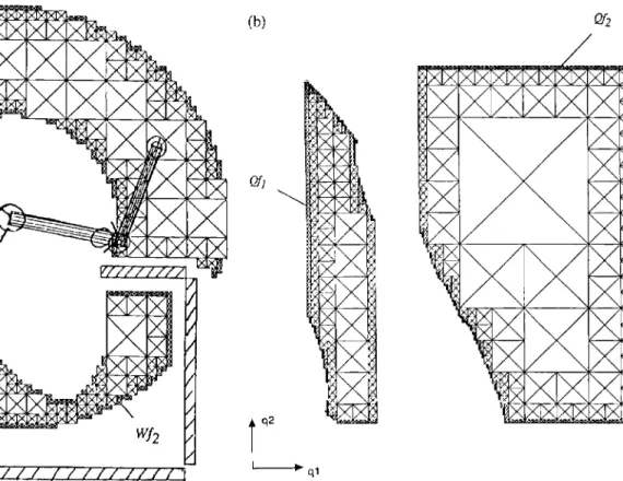
5.3.
Example
3The FW is
connected,
and theconfiguration
free spaceis not connected
(Fig.
7).
In this case, thealgorithm
Fig. 5.
The free
work space is not connected (A, Cartesianspace);
theconfiguration collision-free
space iscomposed of
two connected components
Qh
andQf2
(B,configuration
detects two connected components
(2f,
andQf2
in theconfiguration
free space and exhibits two partsWf
and
Wf2
such thatWf2
cWf and Wfi
= Wf.
So theal-gorithm
concludes that the FW can be traveledthrough
in the senseof P2 ( Wfp)
(and
P, ( Wfp)).
We
verify
thatWf2
can be traveledthrough
in the senseof P3( Wfp)
and thesubspace
Wf - Wf2
in .the sense ofP4(
Wfp).
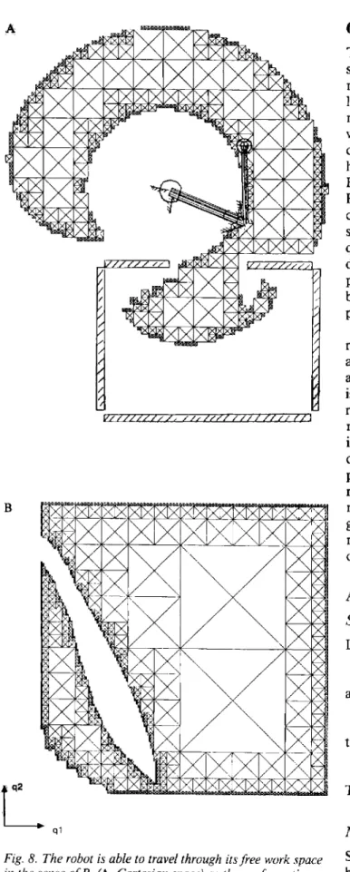
5.4.
Example 4
The FW and the
configuration
collision-free space areboth connected
(Fig.
8).
In thisexample,
thealgo-rithm finds
only
onesingle
connected component inthe sense of
P4 (not
in the sense ofP5,
as we couldverify
that theconfiguration
space iscomposed
of twoaspects, whose
images
in theoperational
space aredifferent).
5.6. Comments
As it has been shown in these
examples, a
simple
con-nectivity
analysis o.f’the configuration collision-free
space is not
sufficient
to characterize thegeometric
space), and their image in the
operational
space(Wf
andFig. 7. The robot is able to travel
through its free
work space in the senseof P2
(A, Cartesianspace)
andthrough
thesub-space
Wf2
in the senseof Pj
(Wfp)
(B). Theconfiguration
properties
of the free
work space. Theconfiguration
collision-free space may be
nonconnected,
whereas the FW can be traveledthrough
(in
the sense ofP, ,
P2,
orP3;
seeexample 3).
On the otherhand,
theconfigura-tion collision-free space may be
connected,
whereascollision-free
space iscomposed
of two
connected components(C, configuration space).
the FW cannot be traveled
through (in
the sense ofP 5;
seeexample
4).
The
analysis
of thisparadox
and thecharacteriza-tions of the
moveability
of the robot in its FW are theFig. 8. The robot is able to travel
through
its free
work spacein the sense
of P4
(A, Cartesian space) as theconfiguration
free
space is connected (B,configuration
space).6. Conclusion
This article presents a
classification,
in theoperational
space, of
regions
where the robot is able to achieve motionsaccording
to itsjoint
limits and the obstacleslying
in the environment. Five characterizations of themoveability
in the work space have beenexplained,
aswell as the five
corresponding
necessary and sufficientconditions. Based on these
conditions,
analgorithm
has been
developed
that tests whetherWf satisfies
PI
orP2
orP3
orP4
and finds all the parts ofWf satisfying
P, ( Wfp)
orP2 Wfp).
Any
robot in any environmentcan be
studied, provided
that the dimensions of thespaces are not greater than three
(our
algorithm
isquite
general
and couldtheoretically
deal with k-dimensional trees, with k >3,
but this would lead toprohibitive computational
time;
when k %3,
thenum-ber of tests is reasonable and
compatible
with theca-pacity
of currentminicomputers).
This work is a new contribution to the
design
of robotic cells. Thegeometric
performances
of the robot among the various obstacles of the cell can beevalu-ated
through
the five characterizations of its FW. Thisis an
interesting
aid for themorphology
choice of arobot. In
addition,
thegeometric
layout
of the cellmay be realized
by
determining
the suitablemoveabil-ity
areas in the environment.Independently,
we havedeveloped
amethodology
thatperforms
the automaticpositioning
of a robot in its environment in order toreach a
given
area(Chedmail
andWenger
1989).
Thismethodology
and the presentstudy
arecurrently
inte-grated
in a softwarepackage
that defines theauto-matic
positioning
of a robot among the variousobstacles.
Appendix
A.
Demonstration of
Property
Pt
1Sufficient
Conditionand so
therefore:
That is the property
Pi.
Necessary
ConditionSuppose
Wf is
notconnected,
then notrajectory
exists between the different connected components ofit,
andSo we suppose that
Wf is
connected and satisfies the propertyPl:
Let Hence asPI
is satisfied. Therefore such that and ElsewhereK is obtained
by
sweeping
the finite set of the partsof I,
the cardinal of which is finite:Card(K)
:s:; 2N - 1.Finally
from
(1)
and(3),
andfrom
(2)
and(3);
therefore i and ii are satisfied.Appendix
B. Demonstration of
Property
P2
Sufficient
ConditionIt is obvious.
Necessary
ConditionSuppose
that: V i EI,
Wf
CWf (strictly).
Thus,
for any i inI,
Df
= Wf -
WjE’is
nonempty.Let Td = (Xl, X2,
... ,Xp)
be a discretetrajectory
inYljf, where p
is the number of connectedcompo-nents of the
configuration
collision-free space: p =Card(I).
Thistrajectory
is chosen such that forany j %
p,Xj
is inDfj.
Thus there exists a discretetrajectory
inWJ~such
that V i EI,
Td
nDf,. ~
0,
which means:Appendix
C. Demonstration of
Property
P3
Sufficient
ConditionSimilarly,
letX~
EWh
then ‘d i EI,
X~
EWJ;,
and soP3
is satisfied.Necessary
ConditionSuppose 3
i E I such that~
CWf (strictly);
let qi EQfi
and letX~
EWf -
Wf ;
thenP3
is false.Appendix
D.
Demonstration of
Corollary
3
(Property
P3 ( Wfp))
Sufficient
ConditionLet
Wfp
C(U~,.
Wf ) -
(Uk~l·
Wfk)
for some I’ in I. Let qi inQfp
and letX
I = f (q, ).
As
X i £ Wfk
forany k
notbelonging
toI’,
thereexists
io
in I’ such that ql EQfp
nQfiO.
Let
X~
inWfp:
d i EI’,
X~
EWfp
n~
and thusX2 E Wfp n WfiO.
Necessary
ConditionLet
D(I’)
=(niEI’
Wx) -
(Uk~l’
Wf~).
The setsD(I’)
make a
partition
ofWh
whenconsidering
allpossible
subsets I’ in I.
Indeed,
they
areclearly
alldisjointed,
and moreover:
Now,
letWfp
inW£
and suppose V I’ CI,
Wfp /
D(I’).
Then,
there exists1’,
and1’Z in I
such thatWfp
nD(I’1) ~ ~
andWfp
nD(I’ 2) =1=
ø.If 1’1 ct
I’2,
then there exists qlin f-’(Wfp
nD(I’,))
such that q,be-longs
to(2fio
forio
inI’, - 1’2.
LetX2
inWfp
nD(I’2);
then the
property
P3( Wfp)
is false.Similarly, if I’, C
I’~ ,
there exists q,in f -’( Wfp
nD(I’ 1 ))
such that qlbelongs
to64
for io
in1’2 -
IZ .
LetX2
inWfp
nD(I’2);
then the propertyP3 ( Wfp)
is false.Appendix
E. Demonstration
of
Corollary
4
( Property
P4 ( WfP))
and
Necessary
ConditionAcknowledgment
This work has been
partially
supported by
the MREScontract
MEC/ 10/ 10:
&dquo;Choix d’architectures de robots&dquo;(Robots morphology
choice).
References
Bernard, F. 1984. CATIA: du dessin au volume, de la
ciné-matique
aux calculsscientifiques,
de la commandenu-mérique
à la robotique, un outil complet de C.F.A.O.Proc. M.I.C.A.D., (2):1082-1097.
Borrel, P. 1986. A
study
of multiplemanipulator
inverse kinematic solutions withapplications
totrajectory
plan-ning
and workspaces determination. IEEEConf
Robot. Automat., pp. 1181-1185.Brady, M., Hollerbach, J. M., Johnson, T. L., et al. 1982. Robot Motion:
Planning
and Control.Cambridge,
Mass.: MIT Press.Brooks, R. A. 1983a.
Planning
collision free motions forpick-and-place operations.
Int. J. Robot. Res. 2(4):19-44. Brooks, R. A. 1983b.Solving
thepath-finding
problemby
good
representation of free space. IEEE Trans.Sys.
Man.Cybernet.
SMC-13:190-197.Canny,
J. F. 1987 (LosAngeles).
A newalgebraic
methodfor robot motion
planning
and real geometry. Presented atIEEE 28th
symposium.
Canny, J. F., and Reif, J. 1987
(Los
Angeles). New lower bound techniques for robot motionplanning
problems. Presented at IEEE 28thsymposium.
Canny,
J. F., and Donald, B. R. 1988.Simplified
Voronoi diagrams. Discrete Computat. Geomet. 3(3):219-236.Chedmail, P., and Wenger, P. 1988 (Karlsruhe, F.R.G.).
Ability
of a robot to move between two points within car-tesian free workspace with an encumbered environment. IFAC Symposium on Robots Control, pp. 73.1-73.6.Chedmail, P., and
Wenger,
P. 1987 (Nantes,France).
Do-maine
atteignable
par un robot: Généralisation de lano-tion d’aspects a un environnement avec obstacles.
Appli-cation aux robots articulés
plans.
Proc. AUM Symposium(2):312-313.
Chedmail, P., and Wenger, P. 1989 (Scottsdale, Arizona,
May
14-19).Design
andpositioning
of a robot in an environment with obstaclesusing
optimal research. IEEEConf
Robot. Automat. Vol. 2.Deligneres,
S. 1987. Choix demorphologies
de robots. Ph.D. thesis, E.N.S.M., Nantes, France.Dombre, E., Fournier, A.,
Quaro,
C., and Borrel, P. 1986.Trends in CAD/CAM systems for robotics. IEEE
Conf
Robot. Automat., pp. (3):1913-1918.
Faverjon,
B. 1984(Atlanta).
Obstacle avoidanceusing
an octree in theconfiguration
space of amanipulator.
1stIEEE
Conf.
Robot. Automat., pp. (1):504-512.Faverjon, B. 1986.
Object
levelprogramming
of industrialrobots. IEEE Int.
Conf
Robot. Automat. 3:1406-1412. Gupta, K. C., and Roth, B. 1982.Design
considerations formanipulators workspace. ASME J. Mechan. Des.
104:704-711.
Hansen, J. A., Gupta, K. C. and Kazerounian, S. M. K.
1983. Generation and evaluation of the workspace of a
manipulator.
Int. J. Robot. Res. 2(3):22-31.Khalil, W., and
Kleinfinger,
J. F. 1986. A newgeometric
notation for open and closed-loop robots. IEEE Int.Conf.
Robot. Automat. 2:1174-1179.
Khatib, O. 1985 (St. Louis). A real time obstacle avoidance for
manipulator
and mobile robots. IEEEConf.
Robot.Automat. pp. 500-505.
Koditschek, D. 1987
(Raleigh).
Exact robotnavigation by
means of
potential
functions: Sometopological
considera-tions. Proc. IEEE Int.
Conf.
Robot.(1):1-6.
Kumar, A., and Waldron, K. 1981. The workspaces of
me-chanical
manipulators.
ASME J. Mechan. Des.103:665-672.
Lenarcic, J., Stanic, U., and Oblak, P. 1988
(Ljubljana,
Yugoslavia).
Optimumdesign
of robot mechanisms based on workspace analysis. Proc. Adv. in Rob. Kin., (1):59-165. Lozano-Pérez, T. 1986(Philadelphia).
Asimple
motionplanning algorithm
for general robot manipulators. Proc.Fifth
Nat.Conf. for the Am.
Assoc.of Art.
Int., pp. 626-631.Lozano-Pérez, T., et al. 1987.
Handley:
A robot system thatrecognises,
planes andmanipulates.
Proc. IEEE Int.Conf.
Robot. Automat.,
(2):843-849.
Martin, D., Martin, P., Plemenos, D. 1985. La modèlisation des solides. Nantes, France, Université de Nantes, Institut de
mathématiques
etd’informatique.
Res. rep.IMI-INFO-R20.
O’Dunlaing, C., Sharir, M., and Yap, C. 1984. Generalized Voronoi
diagrams
formoving
a ladder. NYU-Courant Institute, Robotics Lab., Technical rep. no. 32-33.Paden, B., and Sastry, S. 1988. Optimal kinematics
design
of 6Rmanipulators.
Int. J. Robot. Res. 7(2):43-61.Samet, H. 1979. Connected component
labeling
usingquad-trees.
College
Park,Maryland,
Computer
Science Depart-ment,University
of Maryland.Schwartz, J., and Sharir, M. 1982. On the piano mover’s problem: General
techniques
forcomputing topological
properties of realalgebraic
manifolds. New York, N.Y.,Computer
Science Department, New YorkUniversity,
Vijiaykumar,
R., Waldron, J., and Tsai, M. J. 1986. Geo-metric optimization of serial chain manipulator structuresfor
working
volume anddexterity.
Int. J. Robot. Res.5(2):91-103.
Wenger,
P. 1985. Modélisation du robot et del’environne-ment en vue de la détection de collision. Nantes, France, D.E.A., Université de Nantes, E.N.S.M.
Yang, D. C. H., and Chiueh, T. S. 1986. Workspace of
6-joints
robots with fixed hand orientation. Int. J. Robot.Automat.
1(1):23-32.
Yu, Z.