ÉCOLE DE TECHNOLOGIE SUPÉRIEURE UNIVERSITÉ DU QUÉBEC
THESIS BY ARTICLES PRESENTED TO ÉCOLE DE TECHNOLOGIE SUPÉRIEURE
IN PARTIAL FULFILLMENT OF THE REQUIREMENTS FOR THE DEGREE OF DOCTOR OF PHILOSOPHY
Ph. D.
BY Tan Dan DO
THE EFFECT OF BOLT SPACING ON THE TIGHTNESS BEHAVIOR OF BOLTED FLANGE JOINTS
MONTREAL, JANUARY 13 2012 ©All rights reserved, Tan Dan Do, 2012
THIS THESIS HAS BEEN EVALUATED BY THE FOLLOWING BOARD OF EXAMINERS
Mr. Hakim A. Bouzid, Thesis Supervisor
Département de génie mécanique à l’École de technologie supérieure
Mr. Thien-My Dao, Thesis Co-director
Département de génie mécanique à l’École de technologie supérieure
Mrs. Marie-José Nollet, President of the Board of Examiners
Département de génie de la construction à l’École de technologie supérieure
Mr. Raynald Guilbault, Examiner
Département de génie mécanique à l’École de technologie supérieure
Mr. Silvio De Santis, External examiner Pratt Whitney Canada
THIS THESIS WAS PRESENTED AND DEFENDED
IN THE PRESENCE OF A BOARD OF EXAMINERS AND PUBLIC ON JANUARY 13, 2012
REMERCIEMENTS
Tout au long du déroulement de cette thèse, de nombreuses personnes ont contribuée d’une façon ou d’une autre à ma réussite.
J’aimerais tout d’abord remercier particulièrement et très sincèrement mes directeurs de recherche, le professeur Hakim Bouzid et le professeur Thien-My Dao qui ont permis à ces travaux d’aboutir à leur forme actuelle, pour leur collaboration, leur dévouement et leurs judicieux conseils, leur soutien moral et financier. J’ai eu la chance de bénéficier à leur côté de leur profonde compréhension des problèmes de l’étanchéité en mécanique des solides ainsi que de leur inestimable expérience pour l’utilisation de Matlab et la méthode des éléments finis afin de résoudre les problèmes.
J’aimerais également remercier les professeurs Van Ngan Lê, Henri Champliaud et tous les professeurs du département de génie mécanique de l’École de technologie supérieure pour leur soutien constant et leurs conseils avisés durant ce projet.
Je tiens également à remercier tous mes collègues de l’École de technologie supérieure pour leurs encouragements dans mon travail.
Au cours de cette recherche j’ai pu bénéficier, à différents moments, de l’aide financière de l’École de technologie supérieure par l’intermédiaire des responsables du décanat de la recherche. Que tous soient remerciés pour leur aide grandement appréciée, et à travers eux tout le personnel de l’École de technologie supérieure.
Finalement, je voudrais remercier toute ma famille, mes chers parents, ma femme, mes frères et mes sœurs qui m’ont toujours soutenu.
THE EFFECT OF BOLT SPACING ON THE TIGHTNESS BEHAVIOR OF BOLTED FLANGE JOINTS
Tan Dan DO
ABSTRACT
Bolted flange joints form a part of pressure vessels and piping components, and are used extensively in the chemical, petrochemical and nuclear power industries. They are simple structures and offer the possibility of disassembly, making them attractive for connecting pressurized equipment and piping. In addition of being prone to leakage, they often require maintenance while in operation, in which case the bolts are either retightened, as in hot torquing, or untightened for replacement. Although such maintenance work prevents costly shutdowns, it can nevertheless expose the operator to a potential risk because altering the bolt load can produce a gasket load unbalance, which results in a local gasket contact stress drop below a critical value, causing a major leak, and putting the operator’s life at risk.
This proposal addresses flange deflection variation as it investigates the flange contact stress level unbalance around the flange when the bolts are subjected to a load alteration during operation. This study may serve to help limit the degree of load increase in hot torquing or the maximum number of bolts to be replaced at a time, and to identify the flanges whose bolts cannot be replaced while they are in operation.
The objective of this study is to determine a theoretical approach for identifying and analyzing the effects of initial bolt-up and pressurization on the bolted flange joints, in order to obtain a solution for bolt spacing calculation, according to different gasket contact stress variation levels. Our research breaks down into three parts. The first part, an analytical method based on the theory of circular beams resting on a linear elastic foundation, is developed to predict the circumferential distribution of gasket contact stresses. Finite element
model of symmetry bolted flange joints is created for use in evaluating the analysis. Then, as a second step of this research, an approach based on the theory of a ring on a non-linear elastic foundation behavior is applied in order to get more accurate results than linear model solution. This part is applied to non-linear solution and then validated by finite element analysis. In the third part, a linear regression model is developed to propose bolt spacing calculation procedures for bolted flange joint connections. In industrial practice, this work should help in designing, maintaining and operating technical pressure vessels and piping systems.
Keywords: risk assessment, reliability, bolted flange joints, bolt spacing, in-service maintenance, hot torquing
L’EFFET DE L’ESPACEMENT DES BOULONS
SUR L’ÉTANCHÉITÉ DES ASSEMBLAGES À BRIDES BOULONNEÉS
Tan Dan DO
RÉSUMÉ
Les assemblages à brides boulonnées munis de joints d’étanchéité sont les systèmes de raccordement les plus répandus entre les différents éléments des réservoirs sous pression. Ils sont largement utilisés dans l'industrie chimique, pétrochimique et nucléaire. Ce sont des structures simples et des assemblages démontables. Ce qui les rend plus attractifs pour connecter des équipements sous pression et la tuyauterie. En plus des risques de fuite, ils ont besoin de maintenance en cours de fonctionnement au cas où les boulons doivent être resserrés ou dévissés pour être remplacés. Bien que les arrêts de fonctionnement coûteux soient à éviter, l’entretien en fonctionnement expose l'opérateur à un risque potentiel, car le desserrement d’un boulon peut produire un déséquilibre de la contrainte de compression sur le joint d’étanchéité entraînant un contact local du joint d’étanchéité en dessous d’une certaine valeur critique, provoquant une fuite majeure et de ce fait pouvant mettre en péril la vie de l'opérateur.
Cette proposition aborde la question de la variation de la déflexion du rebord de la bride afin d'enquêter sur le déséquilibre de la contrainte de compression dans le joint lorsque les boulons sont soumis à une modification de charge en fonctionnement. Cette étude peut être utilisée pour aider à limiter l'augmentation de la charge de serrage ou le nombre maximum de boulons qui doivent être remplacés en même temps et identifier les boulons qui ne peuvent pas être remplacés en service.
L'objectif de cette étude est de développer une approche théorique pour identifier et analyser les effets de la charge précontrainte et de la pression sur les assemblages à brides boulonnées afin d’obtenir l'espacement optimal entre les boulons en fonction de la variation de la
contrainte de compression sur le joint d’étanchéité. Notre recherche comprend trois parties. La première partie qui est une méthode analytique basée sur la théorie de la poutre circulaire reposant sur une fondation élastique linéaire, sera développée pour prédire la distribution circonférentielle de la contrainte de compression sur le joint d’étanchéité. Des modèles éléments finis de brides boulonnées symétriques seront créés pour valider cette analyse. Une comparaison des résultats d'études antérieures est nécessaire pour valider la solution analytique linéaire. Ensuite, la deuxième étape de cette recherche consiste en une approche qui a été construite à partir de la théorie de l'anneau sur le comportement d’une fondation non linéaire élastique, permettant d’obtenir des résultats plus précis. La solution non-linéaire doit être validée avec une analyse par la méthode des éléments finis. Dans la troisième partie, un modèle de régression linéaire pour des brides boulonnées sera proposé pour une procédure de calcul d’espacement de boulons. Ce travail aidera les services techniques sur la conception, la maintenance et l'exploitation des réservoirs sous pression et systèmes de tuyauterie.
Mots-clés: évaluation des risques, la fiabilité, assemblages à brides boulonnées, l'espacement des boulons, la maintenance en service, serrage, resserrage
TABLE OF CONTENTS
Page
INTRODUCTION ...1
CHAPTER 1 GENERAL INFORMATION AND THESIS ORGANIZATION ...3
1.1 Introduction ...3
1.2 Bolted flange joint ...3
1.2.1 Raised face type ... 5
1.2.2 Full face type... 6
1.2.3 Metal-to-metal contact type ... 7
1.3 Definition of problem ...8
1.3.1 Loads in bolted flange joint ... 8
1.3.2 Gasket contact stress ... 9
1.4 Thesis organization ...11
CHAPTER 2 LITERATURE REVIEW AND OBJECTIVES ...13
2.1 Introduction ...13
2.2 Analytical approaches ...13
2.3 Experimental approach ...18
2.4 Finite element analysis ...22
2.5 Approaches at ÉTS ...23
2.6 Existing model of bolt spacing ...29
2.6.1 Winkler hypothesis ... 29
2.6.2 Volterra’s model ... 30
2.6.3 Roberts’s model ... 35
2.6.4 Koves’ model ... 35
2.6.5 The TEMA standard [20] ... 36
2.7 Objectives of the study ...37
CHAPTER 3 PROPOSED MODEL OF BOLT SPACING ...40
3.1 Introduction ...40
3.2 Proposed model of bolt spacing ...40
3.2.1 Proposed analytical model ... 40
3.2.2 Linear foundation behavior ... 41
3.2.2.1 Linear solution of flange ... 41
3.2.2.2 Eigenvalues and eigenvectors method to solve the problem ... 46
3.2.2.3 Finite element model ... 53
3.2.3 Non-linear foundation behavior ... 55
3.2.3.1 Non-linear solution of flange ... 55
3.2.3.2 Runge-Kutta method to solve the problem ... 58
3.2.3.3 Finite element model ... 60
CHAPTER 4 PAPER 1: EFFECT OF BOLT SPACING ON THE
CIRCUMFERENTIAL DISTRIBUTION OFGASKET CONTACT
STRESS IN BOLTED FLANGE JOINTS ...65
4.1 Introduction ...69
4.2 Theoretical analysis ...71
4.2.1 Analytical model ... 71
4.2.2 Flange working examples ... 75
4.3 Finite element model ...75
4.4 Discussion ...75
4.5 Conclusion ...77
APPENDIX ...90
REFERENCES ...94
CHAPTER 5 PAPER 2: ON THE USE OF THEORY OF RINGS ON NON-LINEAR ELASTIC FOUNDATION TO STUDY THE EFFECT OF BOLT SPACINGIN BOLTED FLANGE JOINTS ...96
5.1 Introduction ...100
5.2 Analytical model ...101
5.3 Flange working examples ...104
5.4 Finite element model ...105
5.5 Results and discussion ...105
5.6 Conclusion ...107
APPENDIX ...108
REFERENCES ...120
CHAPTER 6 PAPER 3: A SIMPLIFIED METHOD FOR ESTIMATING BOLT SPACINGIN BOLTED FLANGE JOINTS ...122
6.1 Introduction ...125
6.2 Analytical model ...126
6.3 Flange working examples ...129
6.4 Results and discussion ...130
6.5 Conclusion ...133
APPENDIX ...134
REFERENCES ...146
CONCLUSION ...148
RECOMMENDATIONS ...152
APPENDIX I ANSYS PROGRAM: SOLUTION FOR 120 INCHES ...154
APPENDIX III MATLAB PROGRAM: LINEAR SOLUTION ...182
APPENDIX IV MATLAB PROGRAM: NON-LINEAR SOLUTION ...192
APPENDIX V MATLAB PROGRAM: NON-LINEAR SOLUTION ...196
APPENDIX VI MATLAB PROGRAM: REGRESSION MODEL ...201
LIST OF TABLES
Page
Table 2. 1 Nominal flange dimensions ...38
Table 4. 1 Nominal flange dimensions of 24 in. and 52 in. HE flange ...79
Table 5. 1 Nominal flange dimensions of 52 in. and 120 in. HE flange ...108
Table 6. 1 % error in estimating bolt spacing with the formulas ...132
Table 6. 2 % error in estimating bolt spacing with the general formula ...133
LIST OF FIGURES
Page
Figure 1. 1 Bolted flange joint applications [1] ...4
Figure 1. 2 Bolted flange joint – raised face type ...5
Figure 1. 3 Bolted flange joint – full face types ...6
Figure 1. 4 Bolted flange joint – metal-to-metal contact type ...7
Figure 2. 1 Configuration of spiral wound gasket [11] ...16
Figure 2. 2 Principle stress variation during bolt-up ...19
Figure 2. 3 Effect of retightening on maximum principle stress [13] ...20
Figure 2. 4 Experiment for bolted flange joints [13] ...21
Figure 2. 5 Kriging interpolation of gasket non-linear data [16] ...24
Figure 2. 6 Gasket deformation and contact stress model [16] ...25
Figure 2. 7 Radial distribution of gasket contact stress, 16 in HE flange [17] ...26
Figure 2. 8 Gasket stress relaxation, 24 in HE flange [18] ...27
Figure 2. 9 Bolt stress relaxation, NPS A class 600WN flange [18] ...28
Figure 2. 10 Angular position between two bolts ...31
Figure 3. 1 Analytical model of bolted flange joint ...41
Figure 3. 2 Infinitesimal element model of flange – linear foundation behavior ...42
Figure 3. 3 Infinitesimal element model of flange – non-linear foundation ...55
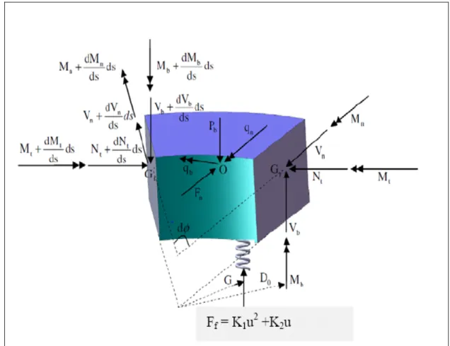
Figure 4. 2 Loads in a bolted flange gasketed joint ...80
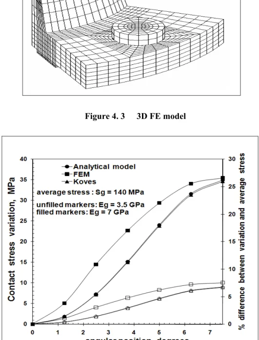
Figure 4. 3 3D FE model ...81
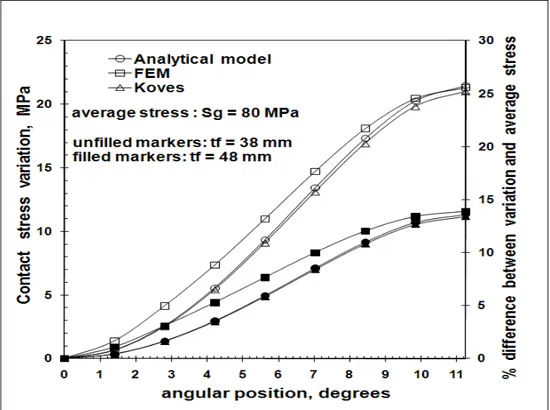
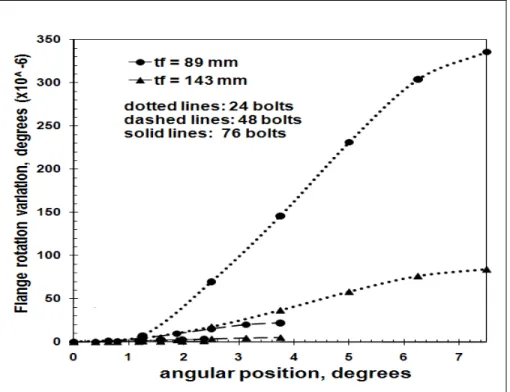
Figure 4. 4 Contact stress variation of 52 in. HE flange tf = 89 mm, 24 bolts ...81
Figure 4. 5 Contact stress variation of 24 in. HE flange Eg = 2 GPa, 16 bolts ...82
Figure 5. 1 Bolted flange joint ...109
Figure 5. 2 Infinitesimal element model of flange ...109
Figure 5. 3 3D FE model ...110
Figure 5. 4 FEA Gasket displacement variations ...110
Figure 5. 5 Gasket displacement variations ...111
Figure 5. 6 Gasket displacement variations ...111
Figure 5. 7 Gasket displacement variations ...112
Figure 5. 8 Gasket displacement variations ...112
Figure 5. 9 Gasket displacement variations ...113
Figure 5. 10 Gasket displacement variations of 120 in HE flange, 68 bolts ...113
Figure 5. 11 Gasket displacement variations of 120 in HE flange, 84 bolts ...114
Figure 5. 12 Contact stress variations of 52 in HE flange ...114
Figure 5. 13 Contact stress variations of 52 in HE flange, tf =50.8 mm ...115
Figure 5. 14 Contact stress variations of 52 in HE flange, tf =142.9 mm ...115
Figure 5. 16 Contact stress variations of 120 in HE flange ...116
Figure 5. 17 Contact stress variations of 120 in HE flange, tf =165.1 mm ...117
Figure 5. 18 Contact stress variations of 120 in HE flange, 56 bolts ...117
Figure 5. 19 Contact stress variations of 120 in HE flange, 68 bolts ...118
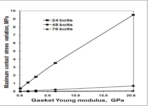
Figure 5. 20 Maximum contact stress variations ...118
Figure 5. 21 Maximum contact stress variations ...119
Figure 6. 1 Bolted flange joint ...136
Figure 6. 2 Bolt spacing of the joint ...136
Figure 6. 3 % different between maximum ...137
Figure 6. 4 % different between maximum ...137
Figure 6. 5 % different between maximum ...138
Figure 6. 6 Relationship between bolt spacing ...138
Figure 6. 7 Relationship between bolt spacing ...139
Figure 6. 8 Relationship between bolt spacing ...139
Figure 6. 9 Relationship between bolt spacing ...140
Figure 6. 10 Relationship between bolt spacing ...140
Figure 6. 11 Relationship between bolt spacing ...141
Figure 6. 12 Relationship between bolt spacing regression ...141
Figure 6. 14 Relationship between bolt spacing regression ...142
Figure 6. 15 Relationship between bolt spacing regression ...143
Figure 6. 16 Relationship between bolt spacing regression ...143
Figure 6. 17 Relationship between bolt spacing regression ...144
Figure 6. 18 Relationship between bolt spacing regression ...144
Figure 6. 19 Relationship between bolt spacing regression ...145
LIST OF ABBREVIATIONS Af Ag bf Bf Bg C D0 Dg db Ef Eg Fb Ff Fg Fn g0, g1 G Gf h0 H Hmax In J K m Mb Mf M0
flange outside diameter (mm) gasket outside diameter (mm)
flange width equals to (Af –Bf) /2 (mm)
flange inside diameter (mm) gasket inside diameter (mm) bolt circle diameter (mm) flange centroid diameter (mm) gasket displacement (mm) nominal bolt diameter (mm) flange Young’s modulus (MPa) gasket compression modulus (MPa) total bolt force (N)
reaction force per unit length (N/mm) gasket force (N)
axial force per unit length (N/mm)
hub thickness at small and big ends (mm) gasket reaction diameter (mm)
shear modulus (MPa) hub length (mm) bolt spacing (mm)
bolt spacing maximum value (mm) flange moment of inertia (MPa) area torsional moment (MPa) elastic foundation constant (MPa) gasket factor
ring bending moment (N.mm)
flange twisting moment per unit length (N.mm/mm) discontinuity edge moment per unit length (N.mm/mm)
Mn Mt nb N0 Nt Pb qb qn R s Sg tf u Vb,Vn yi
ring bending moment (N.mm) ring twist moment (N.mm) bolt number
axial force per unit length (N/mm) ring tangential force (N)
ring axial force per unit length (N/mm)
ring twisting moment per unit length (N.mm/mm) ring bending moment per unit length (N.mm/mm) gasket reaction position radius (mm)
flange circumferential distance at gasket reaction position (mm) gasket stress (MPa)
flange thickness (mm)
axial flange displacement (mm) ring axial shear force (N) variables
Acronyms
ASME CMS HE
American Society of Mechanical Engineers Corrugated metal sheet
Heat Exchanger
LIST OF SYMBOLS
α angular position (rad) β bending rotation (rad) θ flange twist rotation (rad) ε strain
σ stress
INTRODUCTION
Bolted flange joints form a part of pressure vessels and piping components, and are used extensively in the chemical, petrochemical, and nuclear power industries. They are simple structures and offer the possibility of disassembly, making them attractive for connecting pressurized equipment and piping. One of the major concerns encountered in this area is better designing bolted flange joints in order to reduce leakage to minimum acceptable levels. Unfortunately, because the current ASME flange design procedure is not leakage-based, it is difficult to assess its safety level during operation. Leakages generate costs due not only to increased maintenance and shut-downs, but also to penalties for non-observance of environmental regulations. Considerable research has already been undertaken over the last 20 years with the aim of understanding and solving the leakage problems in bolted flange joints. Investigations related to the various causes, such as inadequate tightening of bolts, effects of external bending moment, temperature exposure and bolt spacing, are too few to name.
Experiments show that the leak rates of bolted flange joints are not only dependent on the average contact stress, but also on the way the stress is distributed across the gasket width. The latter is a function of flange thickness, flange rotation, bolt spacing and gasket stiffness.
During operation, the bolts sometimes need to be retightened to compensate the unbalanced forces for relaxation, or to be untightened for replacement. Such manipulations can cause the gasket contact stress to unload locally to critical levels, resulting in serious leaks, and consequently, can harm the operator. It may also result in high local gasket contact stresses, which can crush the gasket, causing serious leaks. Consequently, under steady-state operating conditions, leakage causes multiple environmental and social problems.
Current ASME Code flange design principles are built on a rigid model, but are not based on leakage behavior, and so the recent design solutions according to ASME Code presented provide solutions for commonly encountered situations. However, from time to time, designers are faced with design situations where deviations from economic and
environmental standards are required or requested. ASME standards do not provide a mechanism for evaluating such requests for preventing leakage or hot retorque. Designers must therefore make decisions based on incomplete information and using a considerable amount of judgment gained from experience and codes practices.
Despite a lack of guidance, a new design procedure must be developed to ensure a successful bolted flange joint design and performance. Because information regarding an accurate design procedure is lacking, an analytical approach needs to be developed to solve the leakage problem of bolted flange joints. An analytical solution of the initial bolt-up and pressurization of the joint may be satisfied with both linear and non-linear foundation behavior solutions.
An analytical model supporting a design procedure based on an investigation of the gasket contact stress distribution which may cause a leakage of the joint is proposed in this study, with the model limited only to the raised face flange type. Variations of the contact stress at a mid-bolt location and at a bolt position were studied. This research proposes an analytical solution based on the theory of circular beams resting on a linear elastic foundation to determine the bolt spacing for bolted flange joints according to the different values of the variations of the maximum contact stress and the average contact stress of the joints. The linear relations between the bolt spacing, the gasket Young’s modulus and the flange thickness are covered by the analysis. Then the linear regression model is applied to determine the appropriate bolt spacing values on the response variables, namely, the flange sizes, the gasket compression modulus and the flange Young’s modulus of the bolted flange joints, based on different levels of stress variations compared to the average contact stress.
CHAPTER 1
GENERAL INFORMATION AND THESIS ORGANIZATION
1.1 Introduction
Bolted flange connections have important applications not only for pressure vessels and piping equipment in refineries, but also for equipment in chemical and nuclear industries (Figure 1.1). However, with the need for more onerous service duties, as found typically in the oil and gas exploration industry, there is an increasing requirement for higher operational pressures and temperatures as the industry seeks to go deeper and further in the search for resources. Leakages generate costs due not only to losses but also to penalties for non-observance of environmental regulations. One of the causes behind leakage is poor tightening or a lack of bolts for tightening supports. Work has already been undertaken to understand and solve the problems of leakages of the sealed joints in bolted flange connections. These investigations have covered the various causes of leakages at joints, including the inadequate tightening of bolts, and the external bending moment. These recent investigations do not provide a bolted flange joint design procedure which may control the joint leakage. An analytical approach needs to be developed to solve the leakage problem of bolted flange joints.
1.2 Bolted flange joint
‘Bolted flange joint’ refers to the entire structure, including the pipe, the hub, the flange ring, the gasket and the bolts which connect two pressure components together. During assembly of the structure, two flanges are tightened using bolts, and the gasket located between the flanges provides tightness when the system is under internal pressure. The bolt load holds the flanges together, against the force developed by the internal pressure, which tends to separate them. The normal compressive force works to prevent leakage of the contained pressurized fluid, but is not so great as to crush the surface of the gasket. To help users who demand
reliability and improved gasket performance, the gasket must be put through a variety of tests to evaluate its behavior.
Figure 1. 1 Bolted flange joint applications [1]
Some descriptive details should probably be provided on different types of bolted flange joints. Depending on the available methods used to design bolted flange joints, flanges can be classified under several categories. The technical specifications placed on bolted flange joints are a function of operational conditions, which determine their design. Essentially, there are three different designs available: raised face type, full face type and metal-to-metal contact type.
1.2.1 Raised face type
In the raised face (Figure 1.2) and full face (figure 1.3) bolted flange joints, all loads affect the gasket stress. The bolt load in assembly directly involves a gasket load. All load changes occurring during operations, such as increased or decreased temperature of components,
Figure 1. 2 Bolted flange joint – raised face type
All load changes occurring during operations, such as increased or decreased temperature of components, internal pressure or external forces and moments, result in changes in the gasket, with its stress increasing or decreasing through the loads. The reaction of the connection depends on the stiffness and on the material characteristics of the components.
1.2.2 Full face type
The full face (Figure 1.3) and the raised face type are similar in structure, and differ only in size and in the position of the gasket in the assembly. In this type, the gasket stress is directly affected through the bolt loads.
1.2.3 Metal-to-metal contact type
In metal-to-metal contact type flanges (Figure 1.4), the gasket is deformed in assembly until the flanges reached each other. The gasket may be placed in a groove or in metallic rings to prevent additional deformation when there is a metal-to-metal contact. Increasing the bolt load after getting metal-to-metal contact, there is no further effect on the behavior of the gasket. The tightness of the joint cannot be improved by increasing the bolt load, the gasket stress and therefore the reachable tightness class is fixed when the metal-to-metal contact is reached. A higher bolt load than that required to reach metal-to-metal contact guarantees that the metal-to-metal contact is not lost in service conditions [2].
These three types differ not only in their geometry design, but also in function. For a realistic analysis of the three designs, different calculation algorithms and different gasket factors are required.
1.3 Definition of problem
1.3.1 Loads in bolted flange joint
In popular applications, bolted flange joints support different loads, such as:
- The internal pressure, - Axial loads,
- The bending moment, - The torsion moment, - Thermal load.
Because of the flexibility of the flange ring, the axial movement of one flange relative to the other is not equal throughout the gasket contact area. The displacement at the bolt position has the highest values, whereas the lowest values occur between two bolts. Furthermore, during bolt replacement and hot re-torque, the flange faces move and rotate relative to one another, resulting in a change in the contact stress of the gasket during operation. Experimental data shows that gasket behavior is non-linear and that residual strain occurs after unloading, even though its displacement is small (Figure 1.5). This gasket characteristic should be examined in future investigations.
Figure 1.5 Stress-strain relationship of CMS gasket [3]
Moreover, the amount of flange displacement depends on several factors, one being the space between bolts, also known as bolt spacing. Flange displacement resulting in leakage may be severe enough that inadequate pressure is applied at the mid location between bolts. This effect may be minimized by proper design of the bolt spacing, the flange thickness and stiffness, and the proper selection of gasket materials.
1.3.2 Gasket contact stress
Because of the flexibility of the axial flange movement, the gasket contact stress is not equal throughout the gasket contact area. The gasket contact stress at the bolt position has the highest values whereas the lowest values occur between two bolts. The distribution of the gasket contact stress is non-linear in the circumferential direction, while in the gasket radial direction, stress distribution is linear.
The interaction of the flange and gasket must be controlled for a reliable performance in a bolted flange joint assembly. In general, the tightness of bolted flange joints depends on the contact stress between the flange surfaces and the gasket surfaces. The tension forces in bolts form the compression force between two flanges, resulting in the gasket contact stress, in order to prevent the escape of the confined fluid. The leakage between the gasket and the flanges is affected not only by the average contact stress, but is also significantly affected by the circumferential gasket contact stress distribution. The gasket is used to create a static seal between two flanges and to maintain that seal while in operation conditions which may vary for the internal pressure and loads. The smooth flange finishes during handling and assembly must be considered in specific application. The corrosion and erosion of the flange surfaces during operations have to be taken into account.
In a bolted flange joint assembly, the initial bolt-up stress creates tension forces in bolts, resulting in tightness of the joint, in order to prevent leakage of the fluid in the system. The initial bolt-up stress value should be large enough to lead to efficient sealing of the joint, but it should not be so great as to allow the possibility of scratching and damaging the flange and gasket surfaces.
For wide applications, gaskets come in different types, shapes and sizes, depending on the specific purposes. The gaskets are made from different kinds of materials, including metallic (steel, stainless steel, and copper) and non-metallic (fibers, graphite, PTFE) materials, or a combination of them.
Flange design is probably based on the present ASME/ANSI B16.5 and B16.34 standards which are not based on the leakage behavior and reliability and assessment of the system. Current design procedures are not enough to satisfy today’s technological and environmental requirements which deals with too many problems happening in pressure vessel and piping operating systems. Bolted flange joint connection design must be extensively developed to meet specific applications and current life standard requirements.
1.4 Thesis organization
In the first chapter, the general structure, applications and problems of bolted flange joints will be introduced. The thesis plan should be determined in this chapter. A review of the literature is presented in the next chapter to support this research in identifying the project target and the objectives of the study are presented in that second chapter.
The third chapter introduces the existing bolt spacing model and proposes an analytical approach using the theory of circular beams resting on linear and non-linear elastic foundations to create solutions for bolted flange joints. The linear regression model of bolt spacing is then determined.
In the fourth chapter, the linear solution of bolted flange joints is solved in order to obtain the circumferential distribution of gasket contact stress The first paper for my project “Effect Of Bolt Spacing On The Circumferential Distribution Of Gasket Contact Stress In Bolted Flange Joints” was sent to the 16th International Conference on Nuclear Engineering, ICONE16, Paper No ICONE16- 48634, ASME, Orlando, Florida. It was published by the Journal of Pressure Vessel Technology, ASME, 2011, Vol. 133(4) 041205, 10pp.
The results of non-linear foundation behavior solution of bolted flange joints will be determined in the second paper of my project. The fifth chapter shows the content of the second paper “On The Use Of Theory Of Rings On Non-Linear Elastic Foundation To Study The Effect Of Bolt Spacing In Bolted Flange Joints”. This paper was presented at the 2010 ASME-PVP Conference, Paper No PVP2010-26001, Bellevue, Washington. It ranked as one of the Finalist Papers of the Conference. The presentation was awarded the Winner of the Student Paper Competition, Ph. D category. This second paper was sent to the Journal of Pressure Vessel Technology, ASME, 2010, and was accepted in June 2011.
The content of the third paper is presented in the sixth chapter. The linear regression model is applied to determine the bolt spacing of bolted flange joints. This linear regression model
allowed designing bolted flange joint based on the different levels of contact stress variations, which is related to the leakage. A third paper, titled “A Simplified Method For Estimating Bolt Spacing In Bolted Flange Joints” was submitted to the International Journal of Pressure Vessel and Piping, October, 2011. This paper was also submitted to the ASME 2012 Pressure Vessels & Piping Division Conference, PVP2012, July 15-19, 2012, Toronto, Ontario, Canada.
CHAPTER 2
LITERATURE REVIEW AND OBJECTIVES
2.1 Introduction
Bolted flange joints are widely used in industries because of their simple structures and because they offer the possibility of disassembly, making them attractive for connecting pressurized equipment and piping. They often require maintenance while in operation, in which case the bolts are either retightened, as in hot torquing, or untightened for replacement. Although much research has been done in order to avoid the potential risk of leakage of the joint, bolted flange joints need to be further investigated in order to come up with an appropriate design procedure for new special applications and operations. This proposal presents a general introduction of bolted flange joints and their applications, and then reviews the approaches adopted by researchers in recent years, and finally, defines the objectives of the study, including an action plan of the project.
2.2 Analytical approaches
In 1937, Water et al. [4] proposed formulas for stresses in bolted flanged connections. By using an analytical model for internal pressure on the shell, they advanced a formula for calculating the stresses of the shell and of the flange. Then, in 1939, Labrow [5] offered an analytical approach to designing flange joints. Furthermore, Roberts (1950) [6] focused on the behavior of gaskets of bolted joints under internal pressure. With a similar goal, Wesstrom et al. (1951) [7] developed an analytical method to investigate the effects of internal pressure on stresses and strains in bolted flange connections. More recently, Koves [8] published a study of the effect of external loads on the strength and leakage behavior of flanged joints. Koves introduced the traditional approach under which the flange was analyzed using the shell and plate theory. In that case, the equivalent pressure is computed as the pressure that gives the same maximum longitudinal stress in the flange neck as the applied external forces. The axial force is simply added to the axial pressure thrust force, and
the ASME design procedure is followed for the computation of flange moments. Although this computation is the most commonly used approach, the results are still conservative because the design requires an artificially high pressure, and the required bolt load to prevent gasket leakage is proportional to this pressure.
In 1975, Kilborn et al. [9] carried out a study on the spacing of bolts in flanged joints. The maximum allowable bolt spacing for flange sealing occurs when the pressure at the point midway between the bolts has a zero value. Any further increase in bolt spacing will cause the contact pressure to decrease considerably, with possible separation of the flanges and leakage of the joint. The assumptions in this analysis are that the flanges are flat and that the bolt spacing and flange width are small in comparison to the bolt pitch circle diameter [9]. The curvature of the flange is therefore neglected, and the results will apply to straight flanges, and only approximately to flanges of large diameter. The flange is approximated by a loaded beam with the strengthening effect of the pipe, with the bending of the flange in the radial plane being ignored. In the Kilborn et al. approach [9], it was recommended that maximum bolt spacing for flanges without gaskets should differ greatly from certain bolt spacing called for in flange standards, and that the maximum allowable bolt spacing for flange sealing is considerably affected by the properties of the gasket. The allowable bolt spacing increases if the gasket is thicker, softer or of a smaller width. It is assumed that the maximum allowable bolt spacing for flange sealing occurs when the pressure at the point midway between the bolts has a zero value. Any further increase in the bolt spacing will cause the pressure to go negative, with a separation of the flanges and leakage of the joint. The assumptions of Kilborn in this analysis are that the flanges are flat and that the bolt spacing and flange width are small in comparison to the bolt pitch circle diameter. The curvature of the flange is therefore neglected, and the results will apply to straight flanges, and only approximately to flanges of large diameter [9].
In 2002, Sawa et al. [10] investigated the stress analysis and determination of bolt preload in pipe flange connections with spiral-wound gaskets under internal pressure. This study assumed that the contact stress distribution in a pipe flange connection with a spiral wound
gasket subjected to internal pressure is analyzed by using the axisymmetric theory of elasticity as a three-body contact problem, and Sawa [10] utilized the finite element method by taking into account non-linearity and the gasket hysteresis, where two pipe flanges, including the gasket are clamped together by bolts and nuts with an initial clamping force (preload), and an internal pressure is then applied[10]. Furthermore, leakage tests, which are called room temperature operational tightness tests in the PVRC (Pressure Vessel Research Council) procedure, and experiments concerning a variation in an axial bolt force, were performed in the pipe flange connection with a 3-inch. nominal diameter, using nitrogen and helium gases. It was found that a variation in the contact stress distribution decreases as the gasket thickness increases, and that the contact stress decreases as the internal pressure increases. Sawa’s experiments showed that the values of variation in the contact stress distribution are greater than that obtained by the PVRC tests. This was due to the fact that the contact stress distribution and a change in the contact stress of the pipe flange connection due to the internal pressure were not taken into consideration in the experiments of Sawa et al.. The difference in the values of the new gasket in the present test results obtained by using the actual average contact stress is smaller than in the PVRC test results. In the leakage tests, it was observed that the amount of leakage was greater when helium was used than that when nitrogen was used.
Sawa et al. assumed that when the assembly (a pipe flange connection with a gasket fastened by bolts with an initial clamping force (preload)) is subjected to an internal pressure, a change in axial bolt force occurs in the bolts and the contact force (per bolt) is eliminated, that is, the total axial force (per bolt) due to the internal pressure is equal to the sum of initial clamping force and contact force. Thus the contact stress decreases as the internal pressure increases.
In 2003, Fukuoka and Takaki [11] proposed a finite element simulation of the bolt-up process of pipe flange connections with a spiral wound gasket, where the spiral wound gasket has a very low stiffness in the direction of compression. Spiral wound gaskets are
manufactured by winding a preformed V-shaped metal strip and soft non-metallic filler together under pressure (Figure 2.1)
Figure 2. 1 Configuration of spiral wound gasket [11]
Since such a low stiffness significantly affects the tightening characteristics of pipe flange connections, the objective gasket is modeled as groups of non-linear one-dimensional elements, and the stress-strain relationships of a spiral wound gasket are initially identified in terms of two expressions [11]:
• Loading:
65.2 27.3 10 17.4 10 32.1 10
• Unloading and reloading:
exp
exp exp
(2.2)
103.3 exp 9.9 63.6
exp
where σ and σy are in MPa. εy and σy represent the magnitudes of strain and stress on the loading curve when unloading starts. εr represents the residual strength when perfect unloading occurs from the point (εy, σy), which can be approximated as:
1.25 0.47 (2.3)
Fukuoka and Takaki carried out the procedure of bolt preloads by applying the appropriate amount of longitudinal displacement to the symmetrical cross-section of the bolt body. Results showed that this approach can predict the scatter in bolt preloads with high accuracy, when tightening a flange connection with a number of bolts successively in an arbitrary order. It was observed that at the end of a bolt-up operation, the magnitudes of contact pressure vary significantly in the circumferential direction with a shape similar to a sine curve. However, it is quite difficult to put this to practical use. That is, it is difficult for workers on the job to execute the tightening operation following the prescribed values, since the bolt preloads to be applied differ from bolt to bolt.
In 2007, Koves [12] proposed an approach to determine the contact stress variation between bolts based on the theory of beam on elastic foundation. This analytical approach has a good agreement with finite element analysis for the high flange rating (larger than class 600 flange).
2.3 Experimental approach
In 2006, Abid and Nash [13] concentrated on the gasketed vs. non-gasketed flange joint under bolt-up and operating conditions. A series of experiments using different gasketed and non-gasketed flange joint assemblies were undertaken to examine flange behavior during joint preloading, operating conditions and retightening. For all tests, the same pair of gasketed flanges with three different gaskets of the same dimensions, the same properties and the same materials was used for assembly and then to examine variability in the supplied gaskets as well as the effect on joint behavior. From the initial strain results, it was observed that maximum recommended torque applied could only achieve 30-35% pre-stress of the yield stress of the bolt material. This is very low and results in bolt relaxation during bolt-up and leakage during operating conditions. These preloads avoid gasket crushing, but still provide stresses close to the yield stress of the flange material at certain locations around the flange hub fillet due to flange rotation. Stress variation results during bolt-up and operating conditions were observed as shown in Figure 2.2.
Figure 2. 2 Principle stress variation during bolt-up and operating conditions [13]
Retightening of the joint is carried out when the joint is pressurized up to the proof test pressure. The resulting increase in axial stress at the hub flange fillet is surprisingly high, even though the torque in the bolts is applied very smoothly and carefully with no sudden jerks. After unloading the flange joint, a residual stress is observed at the hub flange and hub pipe fillet locations (Figure 2.3). This shows that the retightening of the gasketed joint during operating conditions adds to the effect of flange straining or yielding. For non-gasketed joints, during retightening, all the bolts are found to be reasonably tight, so it is concluded that there has been no relaxation.
Figure 2. 3 Effect of retightening on maximum principle stress [13]
Abid and Nash [13] investigated the structural strength of bolted flange connections, and presented the problem associated with gasketed joints, and conducted a comparative study of non-gasketed joints under bolt-up and operating conditions to reduce stress variation for improved joint strength. A series of experiments using different gasketed and non-gasketed flange joint assemblies were undertaken to examine flange behavior during joint preloading, operating conditions and retightening (Figure 2-4). For all tests, the same pair of gasketed flanges with three different gaskets of same dimensions, same properties and same material were used in assembly to examine variability in the supplied gaskets and its effect on the joints’ behavior. Similarly, three non-gasketed joint assemblies with and without a secondary seal ring were used. In actual practice, the effect of retightening was not realized, as the main focus was to minimize any leakage by further tightening, as is commonly found in actual pipe joint assembly applications. Experimental results showed that a small relaxation was
observed with gasketed joints, but none with non-gasketed joints during retightening of all the bolts. From principle stress results, it was concluded that during bolt-up and operating conditions, at all locations, the maximum stress in a non-gasketed joint should be lower than the yield strength of the flange material, whereas, in the gasketed joint, stresses in the flange during bolt-up and up to the design pressure are close to the yield stress of the flange material at the hub-flange fillet. From retightening experimental results, it was seen that in the non-gasketed joint, after unloading, bolt relaxation happened. The yielding of the flange provides an additional effect to the relaxation of the joint during bolt-up and any retightening. Thus, it was concluded that good quality bolts with proper surface treatment and proper joint preloading are essential for successful long-term joints. Similarly, use of proper tools and tightening procedures to make the joint assembly is recommended for controlling flange stress variation.
2.4 Finite element analysis
In 1994, Hwang and Stallings [14] recommended a solution for bolted flange connections, involving the application of the finite element method, with a 2-D axisymmetric finite element model and a 3-D solid finite element model of a high pressure bolted flange joint, for investigating the stress behavior. The loads consisted of applied external loads (axial force, shear force, torque, and bending moment), bolt preload, seal load, and internal pressure. The external loads were applied on the top boundary of the pipe section. The axial force and torque were evenly distributed around the pipe. Since the seal load is created by a gasket between the flange joint and the mass container, it was spread uniformly at the location of the gasket in the direction. The bending moment was simulated by applying linearly varying z-direction forces around the boundary of the pipe. The bolt pretensions were obtained by a direct calculation method. The pressure load was assumed to be equally distributed over the inside surface of the duct. Comparisons indicated differences in Von Mises stress of up to 12% at various points due to the non-axisymmetric bolt pretensions. Moreover, in the 2-D model, where the equivalent axial force (for bending moment) and applied axial forces were added, the model underestimated the maximum Von Mises stress obtained from the 3-D model by 30%.
In 2006, Abid [13] carried out investigations to determine the safe operating conditions for the gasketed flange joint under combined internal pressure and temperature, using the finite element approach, which verified the finite element model as compared to the results from classical theories. Abid studied the effect of different thermal expansions on the distortion of individual joint components using ANSYS software. Solid structural elements (SOLID45) were used for structural stress analysis of the flange joint. Given their compatibility with the SOLID45, thermal elements (SOLID70) were used to determine the temperature distribution. Contact elements (CONTA173), in combination with target elements (TARGE170) were used to simulate the contact distribution between the flange face and the gasket surface, the top of the flange and the bottom of the washers. Adaptive meshing was used in high stress
distribution regions, and the boundary conditions were that the flanges were free to move in either the axial or the radial direction. This provides flange rotation and the exact stress behavior in the flange, bolt and gasket. Bolts are constrained in the radial and tangential directions. For thermal analysis, convection with internal fluid temperature on the inside surface of the pipe, flange ring and gasket with ambient temperature at the outer surface of the pipe and flange ring was applied. The results were compared with radial, tangential and longitudinal stresses calculated using Lame’s theory, and were found to be in good agreement. A similar conclusion was found with temperature. The outer surface of the flange ring has a minimum temperature because of the maximum heat transfer. The maximum temperature in the bolt occurs under the bolt head at the inner portion because it is in this portion that heat is first transferred from the flange to the bolt by conduction from the flange top surface and by radiation from the inner surfaces of the bolt hole to the bolt shank. A small temperature variation was observed in the axial direction of the bolt. The gasket was in contact with the flange, and showed a temperature variation only in the radial direction. Abid concluded that the joint will perform effectively for a pressure rating below 8 N/mm2 with 1000C, with leads to the conclusion that at higher temperatures, the internal pressure must be lower for safe operating conditions, and that a joint designed for internal pressure loading is prone to failure, both in terms of its strength and sealing capacity, under additional thermal loading.
2.5 Approaches at ÉTS
In 1995, Bouzid et al. [15] studied the effect of gasket creep relaxation on the leakage tightness of bolted flange joints, with the proposed analytical approach taking into account the flexibility of all the flanged joint members. The finite element computer program ABAQUS (1988) was used to simulate the three-dimensional behavior of a bolted flange gasketed joint, and a series of tests was performed on a pair of NPS 4 ANSI class 600lb flanges, fitted with either of the two PTFE-based gaskets (A and B) of different thicknesses (1/8 inch and 1/16 inch) to investigate gasket creep relaxation. Test results revealed that the general trend of the relaxation behavior of the gaskets tested on the real bolted joints can be
simulated by a creep law of a logarithmic time dependency. It was noticed that the creep relaxation of certain gaskets is more pronounced than for others; that it depends on the material and the thickness, and that flange rotation causes a non-uniform gasket stress distribution which shifts the location of the gasket reaction.
In 2004, Bouzid, A., H. and Champliaud, H. [16] studied the contact stress evaluation of non-linear gaskets using dual kriging interpolation. A gasket’s mechanical behavior is described by the two functions Sg(Xi) for gasket stress and ug(Xi) for gasket displacement, which are based on dual kriging interpolation. The result is a parametric grid that allows the determination of the gasket loading or unloading stress if the displacement is known (Figure 2.5). The solution is then used to obtain one parameter of Sg or ug (Figure2.6).
Figure 2. 6 Gasket deformation and contact stress model [16]
The analytical calculation of the complex gasket contact stress due to non-linear mechanical behavior of the gasket is made possible using dual kriging methodology. Results could be used to investigate the leakage of bolted flange joints due to the gasket stress and gasket deformation resulting from the bolt load change.
In 2005, Bouzid, A. and Nechache, A. [17] proposed an analytical solution for evaluating gasket stress change in bolted flange connections subjected to high temperature loading, where the cylinder shell is treated using the theory of beam on an elastic foundation, the flange is considered to be either a circular plate with a central hole, for a small flange, or a circular ring, for a large diameter flange. The theory of cylindrical shell with linear varying thickness is applied to the hub, and the bolt is represented by a linear elastic spring. This approach proposes equations to determine the radial displacement and rotation of the cylinder
shell, at any axial position on the cylinder, due to pressure and temperature. This analytical solution also presents equations to determine the radial displacement of the hub and the radial displacement, the rotation and the moment of the flange ring. The analytical solution was validated by a three-dimensional finite element model. The loading is applied in three stages. The first stage refers to the initial bolt-up achieved by applying axial displacement to the bolt to produce the initial target bolt stress. The second stage involves applying pressure with an internal fluid. An equivalent longitudinal stress is applied to the shell to simulate the hydrostatic end thrust. The third stage is the heat-up of the joint at the temperature of operation of the internal fluid. A good agreement was found between the analytical model and the finite element model. The gasket contact stress is higher at the gasket outside diameter. In all cases, the gasket load decreases when pressure is applied, as well as after the application of a temperature of 4000C. The use of the proposed analytical solution of the load redistributions in bolted joints subjected to steady-state thermal loading is recommended for large diameter flanges used at high temperatures (Figure 2.7).
In 2007, Bouzid, A. and Nechache, A. [18] presented an approach of creep analysis of bolted flange joints used in high temperature applications. The paper proposed equations to determine the axial displacement of all joint elements (flange, bolt, and gasket) in a flange pair. Creep models and analysis of flange, bolt and gasket were also introduced. Three-dimensional finite element models were constructed to validate the analytical solution and to illustrate the creep effect of each component on the load relaxation, where creep is applied to the bolt and the flange separately, and together and to the gasket, using their corresponding material properties. In this analytical approach the gasket creep model was substantiated for up to 10,000 seconds while the flange and bolt creep models were substantiated for a much longer time of 10,000 hours (Figure 2.8).
Figure 2. 8 Gasket stress relaxation, 24 in HE flange [18]
It was found that, in general, bolted joints relax extensively during the first few hours of service due to the excessive short-term creep of the gasket. In the long term, the contributions of the flange and bolt creep become significant, especially at high temperature, in addition to the gasket degradation and weight loss resulting from thermal exposure. The results show
that the flange circular portion is assumed to behave as a ring instead of a plate. The effect of creep over time on the distribution of the tangential stress with time depends on the creep constants used. The first set of creep constants corresponds to a much higher creep resistant material, and the resultant bolt stress relaxation has a direct impact on the loss of joint tightness (Figure 2.9). In some cases, more than 50% relaxation is obtained after 10,000 hours, and the results of the short-term creep relaxation of the gasket obtained with the analytical model are in substantial agreement with those obtained with the finite element model. The difference between the two methods is less than 5%.
Figure 2. 9 Bolt stress relaxation, NPS A class 600WN flange [18]
The effect of bolt load changes during operation could be avoided by adopting a particular procedure for bolt replacement and hot re-torque. One of the causes of undesirable leakage is poor tightening of, or a lack of, bolts to tighten the joints. Proper procedures for bolt replacement and hot re-torque to reduce stress variation for improved joint strength are important factors which affect the behavior of bolted joints during joint preloading, operation
and retightening. Consideration of the space between bolts, the behavior of gaskets, and the replacement of bolts during maintenance of connections, all of which affect the tightness behavior of bolted flange connections, are objectives of this paper.
During bolt replacement and hot re-torque, the flange faces move and rotate relative to one another, resulting in a change in bolt load during operation. An initial deformation produced in the flange at the hub flange intersection causes an alignment problem for bolt bending, resulting in leakage. This alignment problem becomes apparent when the flange is subjected to operating conditions, and becomes even more serious when it is subjected to a combination of loading conditions [18]. This effect is worsened by adopting procedures such as hammering and flogging, or retightening, which damage not only the flange joint but also the equipment to which the joints are attached. Bolt replacement and hot re-torque change the situation of the static loading regime, causing bolted flange joints to become prone to leakage.
Although a few analytical results are available in the literature highlighting the stress variation behavior in bolted flange joints during bolt replacement and hot re-torque, no assessment of the potential risks of leakage due to load change is available. Therefore, it would be interesting to develop a theoretical approach to this problem that could be used to recommend a procedure for bolt replacement and hot re-torque, ensuring that a joint is tight and leakage is minimized.
2.6 Existing model of bolt spacing
2.6.1 Winkler hypothesis
In the assembly of flanges, bolts and gasket, the flange model is probably assumed to be a circular beam resting on an elastic foundation. The analysis of the bending of flanges on a gasket (elastic foundation) is developed based on the Winkler hypothesis that at every point, the reaction forces of the gasket are proportional to the deflection of the flange at that point.
The vertical deformation characteristics of the foundation are defined through identical, independent, closely spaced, discrete and linearly elastic springs. The constant of proportionality of these springs is known as the modulus of subgrade reaction; this modulus of subgrade reaction, which is assumed to be a mechanical representation of soil foundation, was firstly introduced by Winkler, and is used as the primary input for rigid pavement design. The Winkler model, which was originally developed for use in analyzing railroad tracks, is very simple, but does not accurately represent the characteristics of many practical foundations. Its most significant deficiency is that a displacement discontinuity appears between the loaded and the unloaded part of the foundation surface. So far, the problem of the beam resting on an elastic foundation has been discussed, assuming that the foundation follows Winkler’s hypothesis [19].
2.6.2 Volterra’s model
The flange bending moment is a consequence of axial loads on bolts. The flange model is probably assumed to be a model of a circular beam on an elastic foundation. Volterra calculated the deflection of circular beams resting on an elastic foundation and loaded by symmetrical, concentrated forces acting perpendicular to the plane of original curvature of the beam and at an angular distance 2Ω (an angular distance from one bolt to the next). Volterra’s model [19] is based on the reduction of the two Saint-Venant equations (3.1):
Figure 2. 10 Angular position between two bolts
where
θ twist rotation J torsional moment of area Gf flange shear modulus
Pb bolt force
R curve beam radius
2Ω angular distance between one bolt and the next u axial flange displacement (mm)
s flange circumferential distance at gasket reaction position (mm) and if R I E c R u n f = = 1 η (3.2) R
n f n f b n f f I E R I E R P I E JG 4 2 θ λ υ μ = = = (3.3)
Then equation (3.1) becomes:
t n M d d d d c M d d c = + = − α η αθ μ α η θ 1 2 2 1 (3.4)
where the angle Ω is measured from the bisector of the angle between two points of loading, and the equilibrium equations must be satisfied:
0 0 1 2 2 = Ω − − = − η α α α c d dM d M d M d dMt t n n t (3.5)
The boundary conditions are:
) ( ) ( ) ( ) ( Ω − = Ω Ω − = Ω η η θ θ u c d dM d dM d d d d d d d d d d d d x x 1 2 2 2 2 ) ( ) ( ) ( ) ( ) ( ) ( ) ( ) ( = Ω − Ω Ω Ω − = Ω Ω − = Ω Ω − = Ω − + α α η α η α θ α θ α η α η (3.6)
The solution of Eqs. (3.4) and (3.5) with the above boundary conditions gives the following expressions: [23] (3.7) where 2 3 1 3 1 2 2 2 1 2 2 2 (3.8) with 9 1 27 2 27 1 9 1 27 4 1 1 27 2 27 1 9 1 27 4 (3.9)
The constants C1, C2, . . . and C12 are defined by the expressions:
υ
2 ∆ Ω
υ 2 2 1 3 2 Δ 1 4 Δ υ 2 2 1 3 2 Δ 1 4 Δ 1 1 1 2 1 2 1 1 2 1 1 2 1 2 1 1 2 1 1 2 1 1 4 2 1 1 4 (3.10)
And the constants Δ1, Δ2, and Δ3 are defined by the following expressions:
Δ 3 4 1 ∆ 4 ∆ Ω Ω Ω Ω 2 Ω 2 Ω ∆ 4 ∆ Ω Ω Ω Ω 2 Ω 2 Ω (3.11)
Values of the functions θ/υ, η/υ, Mn/c1υ and Mt/c1υ are given in tables for some values of
the parameters λ and μ [19].
As indicated above, the foundation behaviors of a circular beam resting on an elastic foundation are assumed to follow the hypothesis proposed in 1867 by E. Winkler [19]. The hypothesis that a foundation has an elastic behavior may seem strange; as well, assuming that the effect produced by a concentrated force on the foundation applies only at the point of application is not exactly true since points close to the foundation are also affected [19]. The Volterra method gives the bending deflection solution of a circular beam resting on an elastic foundation in the cases of three, four, six, eight and twelve concentrated forces. However, the method does not support a non-linear foundation behavior solution.
2.6.3 Roberts’s model
In 1950, Roberts [6] introduced a model to determine bolt spacing of bolted flange joints, which was based on the theory of beam on elastic foundation. The solution utilized the numerical summation method to solve the problem for gasket stress distribution in the presence of a large number of bolts. Roberts presents criteria for maintaining 95% of the gasket stress mid-span between bolts. The maximum bolt spacing is determined by the equation:
√1 (3.12)
where
(3.13)
2.6.4 Koves’ model
Koves [12] applied the theory of straight beam on linear elastic foundation to develop a closed form analytical solution that does not require numerical summation. The model is
more accurate than the numerical summation, and allows the determination of gasket stress based on any stress ratio of minimum-to-maximum contact stress as well as flange stress. The standard number of bolts in a bolted flange joint is typically a multiple of four, which provides for symmetry about any centerline between bolts. The Koves model gives the following bolt spacing limit equation:
4 2
(3.14)
The values of are given by table according to the stress ratios of 0, 0.75, 0.8, 0.85, 0.9 and 0.95. The standard gasket factor value m=3 was used along with a conservative gasket modulus of 700 ksi with the actual bolt spacing for a range of ASME B16.5 Class 150 and Class 600 sizes. The actual Koves model would require superimposing Roberts’s model.
2.6.5 The TEMA standard [20]
The current TEMA Code flange design gives the following equation to determine the maximum bolt spacing of the bolted flange joint [20]:
2 6
0.5
(3.15)
The ASME standard then accepted the TEMA standard. The ASME standard does not include the bolt spacing requirements in the Code design rules. The standard is utilized for common applications, and does not provide a mechanism to evaluate leakage behavior.
Because information is lacking regarding an accurate design procedure, an analytical approach to solve the bolted flange joint problem should be developed. The analytical solution of the initial bolt-up and pressurization of the joint may be satisfied with both linear and non-linear foundation behavior. An analytical model supporting a design procedure based on an investigation of the gasket contact stress distribution which may cause leakage of the joint will be proposed in this study. This model is limited to the raised face flange type only.
2.7 Objectives of the study
There are several methods used in calculating bolted joints, and they all concentrate on calculating stress and strain as well as other factors, such as the influence of temperature, relaxation, etc., on the connection. Until now, there has been no method for identifying the potential risks of leakage of a bolted flange joint due to load change resulting from bolt replacement and hot re-torque or bolt spacing of the connection. Following proper procedure is important to maintaining leak tightness between bolts and to avoiding distortion of the flange.
The objective of this study is to determine a theoretical approach for identifying and analyzing the effects of initial bolt-up and pressurization on the bolted flange joints in order to obtain a bolt spacing calculation solution according to different gasket contact stress variation levels. This study will help the industrial practical services on designing, maintaining and operating the technical pressure vessels and piping systems in special applications and hot torquing. The target of the study is to investigate the solution of bolted flange joint raised face type. Five flange sizes, namely, 4 inch, 16 inch, 24 inch, 52 inch and 120 inch Heat Exchanger (HE) flanges are investigated. The nominal flange dimensions are shown in table 2.1.
Table 2. 1 Nominal flange dimensions Flange size (in) Af in (mm) Bf in (mm) C in (mm) g0 in (mm) g1 in (mm) h in (mm) 4 in 10¾ (276) 3⅝ (92) 8½ (216) ¼ (6) 1 (25.4) 2 (50.8) 16 in 25½ (648) 16½ (419) 22½ (572) ¼ (6) 1 (25.4) 2 (50.8) 24 in 29½ (749) 23¼ (590) 27⅝ (701) ⅜ (10) ⅝ (16) 1½ (38) 52 in 58⅜ (1483) 51 (1295) 56¼ (1429) ⅝ (16) 1⅛ (29) 1¼ (32) 120 in 127 (3226) 120¼ (3055) 124½ (3162) ⅝ (16) 1⅛ (29) 3⅛ (32) Flange size (in) tf in (mm) nb db in (mm) Ag in (mm) N in (mm) 4 in 0.8(20) 0.9(23) 1(25.4) 1.1(28) 12 8 4 4 1(25.4) 1¼(32) 1½(38) 1½(38) 5⅜ (142) ½ (12.7) 16 in 1½(38) 1¾(48) 2(50.8) 2¼(57) 20,16,12,8,4 1(25.4) 1¼(32) 1½(38) 1½(38) 18¼ (464) ½ (12.7) 24 in 1 1½(38) 32,28,24,20 16,12,8 1(25.4) 1¼(32) 24½ (622) ½ (12.7)
1¾(48) 2(51) 1½(38) 1½(38) 52 in 2(51) 3½ (89) 5⅝(143) 5⅝(143) 72,68,64,60 56,52,48,44 40,36,32,28 24,20,16 12,8 1(25.4) 1¼(32) 1½(38) 1½(38) 53⅛ (1349) ½ (12.7) 120 in 3(75) 4½(114) 6½(165) 84,80,76,72 68,64,60,56 52,48,44,40 36,32,28,24 20,16,12,8 1(25.4) 1¼(32) 1½(38) 123 (3124) ½ (12.7)
CHAPTER 3
PROPOSED MODEL OF BOLT SPACING 3.1 Introduction
Bolted flange joints have three major components: flanges, bolts and gasket, which, in order to work properly, must all be considered together as a system during the design process. The performance and success of a reliable assembly depend on the quality and design procedure. Additionally, the joint must be robust enough to prevent the acts of warping, distortion or separating during service. Furthermore, service factors, such as thermal stresses, differential expansion, external load, vibration and hot retorque must be considered on specific applications. As a result, under steady-state operating conditions, leakage causes multiple environmental and social problems.
3.2 Proposed model of bolt spacing
3.2.1 Proposed analytical model
The analytical model, which is limited to the raised face flange type only covers the contact stress and the flange deformation of the bolted joints subjected to initial bolt-up and pressurization (Figure 3.2). Determining an accurate design procedure for the bolted flange joint requires a flexibility analysis of the bolted joint assembly. Figure 3.2 [21] shows the flexibility interaction model used in this study. In this model, the flexibility of the flanges, the gasket and the bolts, the flange deflections and rotations resulting from the initial bolt-up and pressurization are considered. The model of our research can satisfy the technical specifications of bolted flange joints using both hypothesis of linear and non-linear elastic foundation behavior. The linear and non-linear elastic foundation behavior will be defined in the next chapters.
![Figure 2. 2 Principle stress variation during bolt-up and operating conditions [13]](https://thumb-eu.123doks.com/thumbv2/123doknet/7692806.244174/37.918.194.806.157.627/figure-principle-stress-variation-bolt-operating-conditions.webp)
![Figure 2. 7 Radial distribution of gasket contact stress, 16 in HE flange [17]](https://thumb-eu.123doks.com/thumbv2/123doknet/7692806.244174/44.918.215.799.629.1023/figure-radial-distribution-gasket-contact-stress-flange.webp)