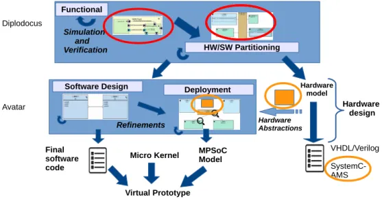
Hardware / Software / Analog System Partitioning with SysML and SystemC-AMS
Texte intégral
Figure
![Figure 2 shows a TDF cluster in the representation defined in the SystemC AMS standard [6]](https://thumb-eu.123doks.com/thumbv2/123doknet/11646848.307922/4.918.490.803.288.382/figure-shows-tdf-cluster-representation-defined-systemc-standard.webp)


![Table 1. Average latencies compared to those obtained in [18]](https://thumb-eu.123doks.com/thumbv2/123doknet/11646848.307922/10.918.186.730.129.464/table-average-latencies-compared-obtained.webp)
Documents relatifs
Mahloojifar, “A low-complexity adaptive beamformer for ultrasound imaging using structured covariance matrix,” IEEE Transactions on Ultrasonics, Ferroelectrics, and Frequency Control
This has shown that the triple layer approach is not limited to simple linear systems and it can well be applied to nonlinear ones while keeping the overall control design
Functional Structural Plant Models (FSPM) simulate individual plant development and growth, they build plant architecture on the basis of biomass production and partitioning
10 shows a protocol model of the security concern composed from PMs Employee Main, Clock, Singleton, Password Handler and Want Time Out.... The specification of a PM is described in
Using this representation, the SystemC-MDVP simulator can can detect time synchronization issues between the TDF and the DE MoCs before the simulation phase starts, providing as
Since the introduction of an interaction field as intended by the received view seemingly changes physics (those fields are even directly observable themselves), it is necesary
In practice, efficiency of HW/SW interfaces is obtained with a direct integration of SystemC high level communication library in hardware, that is by a joint
Notre approche consiste à générer du code SystemC-AMS à partir d’un modèle SysML annoté avec des éléments qui donnent la sémantique d’exécution de chaque bloc SysML et
