HAL Id: hal-00872989
https://hal.archives-ouvertes.fr/hal-00872989
Submitted on 14 Oct 2013
HAL is a multi-disciplinary open access
archive for the deposit and dissemination of
sci-entific research documents, whether they are
pub-lished or not. The documents may come from
teaching and research institutions in France or
abroad, or from public or private research centers.
L’archive ouverte pluridisciplinaire HAL, est
destinée au dépôt et à la diffusion de documents
scientifiques de niveau recherche, publiés ou non,
émanant des établissements d’enseignement et de
recherche français ou étrangers, des laboratoires
publics ou privés.
Ultra-wideband positioning for assistance robots for
elderly
David Espes, Ali Daher, Yvon Autret, Emanuel Radoi, Philippe Le Parc
To cite this version:
David Espes, Ali Daher, Yvon Autret, Emanuel Radoi, Philippe Le Parc. Ultra-wideband positioning
for assistance robots for elderly. The 10th IASTED International Conference on Signal Processing,
Pattern Recognition and Applications (SPPRA 2013), Feb 2013, Austria. pp.8. �hal-00872989�
ULTRA-WIDEBAND POSITIONING FOR ASSISTANCE ROBOTS FOR
ELDERLY
David Espes*, Ali Daher†, Yvon Autret*, Emanuel Radoi*, Philippe Le Parc* * Universit´e Europ´eenne de Bretagne, France
Universit´e de Brest; CNRS, UMR 6285 Lab-STICC Brest, France
E-mail: [email protected] † Universit´e Libanaise
Saida, Liban
ABSTRACT
In this paper, we suggest to use low cost robots and Ultra wideband (UWB) technology in order to help elderly. In the context of the targeted application, a mobile robot is designed to remotely interact with a person acting as su-pervisor, and also to monitor their environment. UWB is then very helpful to ensure precise localization of the robot inside the house.
First, we present our experimental robotic platform, based on of-the-shelves components, and our experimen-tal software environment in the cloud. Then, we describe our localization approach which relies on two phases: Time of Arrival (ToA) estimation using the dirty template algo-rithm, and Bancroft method for the robot position estima-tion. Finally, our simulation results are presented and dis-cussed.
KEY WORDS
Ambient Assisted Living environments, remote controlled robot, UWB localization
1
Introduction
Population aging raises the dependency level of the elderly. To maintain old people in their houses, some mechanisms are needed to take care of them. Mobile Ubiquitous De-vices (MoUD) such as remote controlled robots represent an interesting approach to monitor environment and carry supply to the elder people. These MoUD have to be specif-ically designed for Ambient Assisted Living environments (AAL).
For us, a first typical application, to help elderly who live in their houses and sometimes have difficulties to move, is to use a MoUD carrying a camera, that could help them to monitor their house either indoors or outdoors, for example to see what is going on or simply to watch what their favorite pet is doing. A second typical application is the use of the MoUD by relatives or caregivers to check that everything is ok and to communicate with the inhabitants of a house from everywhere. Relatives and caregivers will
take the control of the MoUD and will be able to start an inspection or a discussion. Ethic questions have to be taken into account in such a project, because the camera may be seen as intrusive. Several studies that have been conducted in this domain [1] show that people are ready to loose some privacy, in exchange of more autonomy in their life, and the opportunity to remain longer in their home; [2] concludes that mobile robots are considered to be less intrusive than fix cameras. These ethic questions are not in the scope of this paper, but are taken into account in the whole project.
In order to design such a MoUD, engineers have to face several challenges such as defining a robotic base adapted to houses, providing communicating systems for the local and distant users (dependant person, and its rela-tives or caregivers), insure safety and security and also pro-viding a precise positioning of the MoUD, in order to help the control of its displacement. To fix this last challenge, we propose to investigate the use of UWB signals. Our ob-jective is to obtain a localization accuracy of about one or two centimeters, which make it possible to have accurate displacements.
In the first section of this paper, we will concentrate on the experimental platform we have defined, including hardware and software. In the second section, we will de-scribe the UWB use within this context, and in the last sec-tion, we will conclude and give some new research objec-tives.
2
Experimental platform
Many robots (and by extension, robots are MoUD) have been designed for assisted living. They are often known as companion robot such as those built by the IRT Research Institue in Tokyo and presented in [3]. These robots look like humanoids and are able to open doors, to clean rooms or to use washing machine. In [4], a robot is used to sup-port cognitive stimulation and therapy management. Many other projects may be found in literature. These robots have generally the size of a child, can move inside their envi-ronment if this one is not too dense, are able to catch
ob-jects and are wearing multimedia interfaces. They are also equipped with dozens of sensors. Energy is also an impor-tant issue for them.
In AAL environment, the total cost of the MoUD is a key point. It must be kept as low as possible especially in the case of elderly who often have tight budgets. This means that the MoUD must be built by using low-cost com-mercial components. Moreover, as network, software or mechanical failures are unavoidable, reliability is another major key point as well as the capability to easily fix them. The robots presented in the previous paragraph do not meet these constraints.
In the following subsection, we propose a low cost robot structure. This solution complies with ”Home and community health and wellness”, following the classifica-tion of [5]. More generally, it may be used in the context of remote presence, as explained in the introduction of this paper. Our MoUD is not an autonomous robot and it has to be controlled either locally or remotely.
2.1 A low cost robot
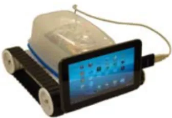
In the aim to increase the reliability and reduce the prices, the MoUD is built with a basic of-the-shelfs hardware components (see figure 1): a robotic platform (Rover 5) with tracks, an electronic component (Phidget board) and a tablet PC. The Phidget board is used to connect the Rover 5 motor to a Tablet PC. The total cost is estimated around 250e. In case of failure of one component, it can be re-placed very easily, as this system is almost plug and play. Compared to other commercial MoUD, such as Rovio[6] or Miabot[7] our prototype can move on more different sur-faces and is much more open to embed free or commercial softwares, in order to offer numerous services.
Figure 1. Robot: Rover 5 base + Phidget (inside the box)+ Tablet PC
The battery autonomy of our prototype is a weak point because we have no automatic come back to a charging dock. When using standard batteries, the MoUD can move continuously for half an hour, but this drawback could be overcome using more batteries of better quality. If the MoUD remains active without moving, the autonomy is of several hours and during this time the MoUD can send pic-tures taken by the webcam and wait for commands.
We are using the tablet PC to communicate, either via an internet box through Wifi connection, or when Wifi is
not available, through a 3G connection (in this case the price of the tablet is a bit higher). Two Android applica-tions must be installed on the tablet PC. The first one is used to send pictures taken by the webcam of the tablet PC to the distant server. The second Android application is used to control the MoUD move when it receives commands from the remote server. It is nothing else but a Java thread which sends HTTP requests to the remote server. When the dis-tant user sends a command to control the MoUD move, the remote server sends a response to the MoUD.
2.2 Software architecture
As our MoUD has to be used remotely, the definition of a software architecture, based on a middleware, has to be done. Several general solutions, such as UniversAAL[8] have been proposed and their use for our preoccupations is under consideration. For our prototype, decision was made to use classical framework based on web servers and to rely on previous work performed in our laboratory (SAT-URNE: Software Architecture for Teleoperation over Un-predictable NEtwork[9]).
In HAL environments, the architecture has to be easy to deploy and to secure. We also take into account that old people should not have to configure the MoUD. This one has to be a plug and play system and has to be able to communicate with a remote server, using a classical In-ternet connection through the outgoing port 80, avoiding any firewall configuration as example.The only configura-tion needed is the Wifi access configuraconfigura-tion (or 3G access configuration if required).
Consequently, the MoUD cannot include any server (neither web nor specific) and cannot wait neither HTTP requests nor any other request. In our proposal, our robot will send HTTP requests to a remote server and will wait for its HTTP responses.
On the user side, the distant user will only send HTTP requests and will wait for HTTP responses. The only thing required on the user side will be a Web browser, for ex-ample, running on a smartphone, a tablet PC or a classical computer. No configuration has to be made.
To make the whole system work, a distant server in the cloud (see figure 2) is needed, which will connect both sides. The distant user has no direct access to the robot but sends a robot command to the distant Web server through a Web interface. The distant server then forwards the com-mand to the robot.
The technical mechanism is presented rapidly in the following.
1. Encapsulating robot commands into HTTP requests: To send commands to the robot, the distant user uses a Web interface which displays buttons and various fields: it is nothing else but a Web form. For example, the distant user clicks on the “MOVE FORWARD” button to make the robot move forward. Parameters can be used, for example, how long the robot must
Figure 2. General system architecture
keep moving. The Web browser will automatically encapsulate the parameters of the robot command (i.e the Web form) inside an HTTP request. The distant server processes the request as soon as it is sent. 2. Processing HTTP requests by Servlets: To process
HTTP requests on the distant server, an Apache Web server[10] is used. The received requests are first forwarded to a second Web server which is a Tom-cat Web server[11]. Servlets running on the TomTom-cat server process the requests and extract the parameters. The Apache server is only used to provide a standard access on port 80.
3. Forwarding requests to the robot: To make the sys-tem work, as no server is installed on the robot, the robot first sends an HTTP request to the distant server. The request is processed by a Servlet and let pending. As soon as the distant user sends a robot command, the HTTP request processing resumes and an HTTP response is sent to the robot. The robot command is inserted into the HTTP response as a serialized object. If the distant user does not send any robot command within a few seconds after its request, a timeout is trig-gered on the robot system. The robot stops waiting for the current HTTP response. A new HTTP request is sent to the distant server to wait for a robot command. 4. Acknowledgment: An optional acknowledgment can be sent from the robot to the distant server. As soon as the robot has received or terminated a command, it can send an HTTP request to the distant server. This optional acknowledgment can also be sent from the distant server to the distant user.
In addition, security has to be insured by a classical login/password approach or data encryption. The whole system has also to be fault tolerant, because many devices and networks will be used from the robot to the final user.
In case of failures of one (or more) component, procedures have to be applied, in order to give as much as possible in-formation to the user, to diagnose automatically the failures and to try to get around the problem. Scenarios in case of failures of one component has to be defined at high level and included inside the different part of the system: robot, server and client.
This global approach has been tested on our prototype and makes it possible to have an operational MoUD, that can be controlled locally and remotely.
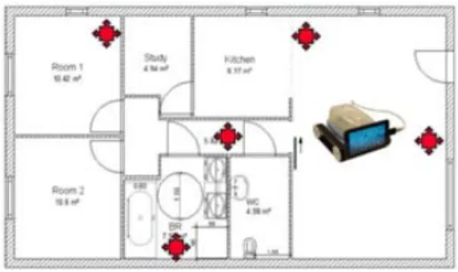
2.3 Positionning system
One drawback of our system is the difficulty to localize the MoUD inside the environment. We would like to extend the previous architecture, in order to add a positioning system based on UWB technology (Fig. 3, and section 3). Some base stations (with known positions) will be distributed in-side the environment. They will send a UWB pulse peri-odically. A UWB receptor will be added on the MoUD. The latter will be able to determine its position (3D) after receiving pulses from at least four UWB transmitters, with a 1-2 centimeters accuracy.
Figure 3. Positionning architecture
The localization will reduce the complexity of the control interface dedicated to the distant user. The web in-terface will contain the cartography of the house, and the robot will be able to reach a destination or a person, only by clicking on the map. The MoUD also will be able to come back to his charging dock, to avoid obstacles with the help of the camera (image processing) and go through the doors of the house.
Moreover, by adding a UWB sensor on the inhabitants of the house, the robot will be able to reach them automat-ically and to bring them supplies (for example medicine, walking stick. . . ) or multimedia devices (for example cam-era, tablet PC, phone. . . ).
Our first studies on UWB positioning are presented in the following section.
3
UWB positionning
UWB radios are defined to be systems using signals with relative bandwidths larger than 20% or absolute
band-widths of at least 500 MHz. Impulse based UWB is char-acterized by the transmission of extremely short duration pulses typically on the order of nanosecond to form a communication link [12]. To protect radio services from UWB interference, the Federal Communications Commis-sion (FCC) has assigned conservative emisCommis-sion masks be-tween 3.1 GHz and 10.6 GHz for commercial UWB de-vices. The maximum allowed power spectral density for these devices is 41.25 dBm/MHz. After the FCC allowed the limited use of UWB systems, two types of standards have been proposed by IEEE working groups for both High Data Rate (HDR) and Low Data Rate (LDR) Wireless Per-sonal Area Network (WPAN).
One of the main features of UWB signals is their po-tential for accurate position location and ranging. UWB technologies are often described as the next generation of real time location positioning systems. Due to their fine time resolution, UWB receivers are capable of accurately estimating the time of arrival of a transmitted UWB signal. This implies that the distance between an UWB transmitter and an UWB receiver can be precisely determined.
This feature of high localization accuracy makes the UWB an attractive technology for diverse ranging and in-door localization applications. This allows various appli-cations that require an accurate estimate of the position in indoor environments, such as a remote control of indus-trial mobile robots, management of stocks in warehouses, mobility assistance for disabled persons and monitored pa-tients in hospitals. UWB signaling is very suitable in this context as it allows centimeter accuracy in ranging and promises the realization of low-power and low-cost com-munication systems [13].
Commercial systems that use UWB sensors for indoor asset tracking are already available. For example, Zebra Enterprise Solutions [14] which uses a localization algo-rithm based on time-difference-of-arrival (TDoA) estima-tion and Ubisense system [15] which uses a combinaestima-tion of TDoA and angle-of-arrival (AoA) estimation. The spec-ified real-time accuracy of these systems is sub-15 cm with indoor operating ranges of over 50 m to 100 m. With the recent advances in semiconductor device technology and the FCC’s approval of the unlicensed use of UWB sys-tems, UWB development has moved from research labs and classified military projects to the commercial sector. Semiconductor companies, like Decawave [16], begin to design and produce complete, single chip CMOS Ultra-wideband IC for transceivers which are complying with the IEEE802.15.4a standard and are based on UWB tech-nology, allowing building different RTLS systems. Un-like commercial systems, some authors propose position-ing system for mobile robots. In [17], the authors propose a selection of components (type of antennae, design of the transmitter or receiver...) and an algorithm to enhance the position of the base stations in the localization space in the aim to avoid NLOS condition. The results show that the positioning error is less than 25 centimeters. In [18], the authors propose a probabilistic model to characterize UWB
ranges error in line of sight. This model is applied to a par-ticle filter that realises data fusion from the readings of the base stations and the vehicle odometry. Results show an average positioning error of about 5cm.
Our positioning system has to yield an accuracy of a 1−2 centimeters to control it precisely. The previous so-lutions are not accurate enough to satisfy these needs. To reach such a precision, we design the UWB pulse to op-timize the spectral effectiveness. Hence the symbols are easier to detect and the effects of multipath reflection are reduced. Moreover we propose a localization algorithm based on Time-of-Arrival (ToA) estimation to ensure the required precision. Our localization algorithm is based on two step positioning approach in which certain parameters are extracted from the signals first, and then the position is estimated based on those signal parameters.
In the first step, signal parameters, such as the ToA in our case, are estimated using the Dirty Template algorithm. These parameters allow then estimating the ranges between the target node and the reference nodes. Then, in the sec-ond step, the target node position is estimated based on the signal parameters and range measurements obtained from the first step using the Bancroft algorithm.
3.1 Dirty Template algorithm
In order to perform time-based ranging successfully, the ToA of the received signal should be estimated accurately. The conventional ToA estimation technique is performed by means of matched filtering or correlation operations. Fine time resolution of UWB signals makes accurate iden-tification of the first Multi Path component (MPC) possi-ble. However, this may not be easy in many scenarios due to non-line-of-sight (NLOS) propagation and a vast num-ber of MPCs. Estimation of the ToA could be affected by several errors (multipaths, interference, attenuation, clock drifting, etc.). Therefore, finding a good estimation of the ToA could be a challenging task in the presence of mul-tipath and interference. In our paper, we consider only the LOS case and we use the dirty template algorithm [19] which allows estimating the ToA in the presence of MPCs. The dirty templates algorithm is a low complexity ToA estimator which operates on symbol-rate samples. The basic idea behind this algorithm is as follows. The opti-mal template signal is not available during ToA estimation. However, the received signal itself can be used as a corre-late tempcorre-late, which is noisy (“dirty”). Then, using cross-correlations of the symbol-length portions of the received signal will lead to estimate the ToA. A detailed version of the algorithm may be found in [20].
3.2 Bancroft algorithm
In three-dimensional geometry, the trilateration technique uses four reference nodes to calculate the position of the target node. To be localized the target node should locate
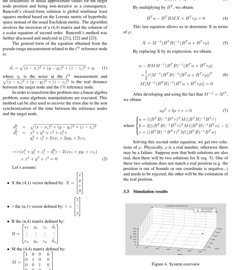
at the intersection of four spheres centered at each ence position. When the signal received from the refer-ence nodes is noisy, the system is non-linear and cannot be solved. An estimation method has to be used. An estimation of the target position can be solved directly without the process of linearization, thereby not requiring the availability of initial approximate values for the target node position and being non-iterative as a consequence. Bancroft’s closed-form solution is global nonlinear least squares method based on the Lorentz metric of hyperbolic space instead of the usual Euclidean metric. The algorithm involves the inversion of a (4,4) matrix and the solution of a scalar equation of second order. Bancroft’s method was further discussed and analyzed in [21], [22] and [23].
The general form of the equation obtained from the pseudo range measurement related to the ithreference node is:
˜ di =
p
(x − xi)2+ (y − yi)2+ (z − zi)2+ ηi (1) where ηi is the noise at the ith measurement and p(x − xi)2+ (y − yi)2+ (z − zi)2 is the real distance between the target node and the ith reference node.
In order to transform this problem into a linear algebra problem, some algebraic manipulations are executed. This method can be also used to recover the error due to the non synchronization of the time between the reference nodes and the target node.
˜ d2 i = p(x − xi)2+ (y − yi)2+ (z − zi)2 ˜ d2 i = x2+ y2+ z2+ x2i+ y2 i + z2i + 2xxi+ 2yyi+ 2zzi =>(x2i + yi2+ zi2− ˜d2i) − 2(xxi+ yyi+ zzi) + x2+ y2+ z2= 0 (2) Let’s assume:
• X the (4,1) vector defined by: X = x y z 0
• τ the (n,1) vector defined by: τ = 1 .. . 1
• B the (n,4) matrix defined by: B = x1 y1 z1 d˜1 .. . ... ... ... xn yn zn d˜n
• M the (4,4) matrix defined by: M = 1 0 0 0 0 1 0 0 0 0 1 0 0 0 0 −1 • α = 1 2diag(BM B T) • ρ = 1 2X TM X = 1 2(x 2+ y2+ z2)
Therefore, the system can be written as:
α − BM X + τ ρ = 0 (3) By multiplying by BT, we obtain:
BTα − BTBM X + BTτ ρ = 0 (4) This last equation allows us to determine X in terms of ρ:
X = M−1(BTB)−1(BTα + BTτ ρ) (5) By replacing X by its expression, we obtain:
α − BM M−1(BTB)−1(BTα + BTτ ρ) +1 2τ [M −1(BTB)−1(BTα + BTτ ρ)]T M [M−1(BTB)−1(BTα + BTτ ρ)] = 0 (6)
After developing and using the fact that M−1= MT, we obtain: aρ2+ bρ + c = 0 (7) where a = ((BTB)−1BTτ )TM ((BTB)−1BTτ ) b = 2[((BTB)−1BTτ )TM ((BTB)−1BTα) − 1] c = ((BTB)−1BTτ )TM ((BTB)−1BTα) Solving this second order equation, we get two solu-tions of ρ. Physically, ρ is a real number, otherwise there may be a failure. Suppose now that both solutions are also real, then there will be two solutions for X (eq. 5). One of these two solutions does not match a real position (e.g. the position is out of bounds or one coordinate is negative...) and needs to be rejected, the other will be the estimation of the real position.
3.3 Simulation results
In this section, we show the results of Matlab simula-tions. An overview of the system with four reference nodes is shown on Figure 4. In our simulations, four reference nodes are placed in the four upper corners of a room of size 6 × 6 × 3 m and the target node is a robot located randomly somewhere on the floor of the room. The reference nodes emit the UWB signals while the target node receives them.
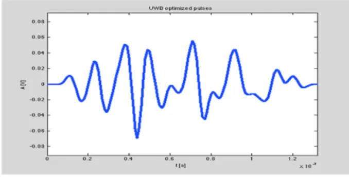
Figure 5. B-spline based UWB pulse
In order to meet certain performance requirements un-der practical and regulatory constraints, UWB ranging sig-nals should be designed appropriately [24]. We have used a specially designed, B-spline based UWB pulse, given in Figure 5, with time duration TP = 1.28 ns, which fulfills the FCC mask constraints and also optimizes the spectral effectiveness.
Figure 6. Channel impulse response
The channel model used is a line of sight channel and is characterized by the impulse response given in Figure 6. Each pulse represents a multipath reflection. The multi-path reflection duration is higher than the symbol duration. Hence, the interference between symbols is quite impor-tant.
As we know, in a two-step positioning algorithm, the positioning accuracy increases as much as the position re-lated parameters in the first step are estimated more pre-cisely. Therefore, in the first step, we analyze the perfor-mance of the ToA estimation using the dirty template algo-rithm. The performance is assessed using the ranging errors of each measurement. Figures 7 and 8 show respectively the ToA estimate and the ranging accuracy concerning the
UWB signals of the first reference node for various SNR (Signal to Noise Ratio) values. We show the normalized mean square error which is approximated by the mean of a hundred trials per point. Similar results are obtained for the other reference nodes.
Figure 7. Mean ToA estimation Error for reference node 1
Figure 8. Mean Range estimation Error for reference node 1
From Figure 7 we can see that the dirty template al-lows us to rapidly approach the accuracy limit for high SNR values even in the presence of MPCs. Figure 8 shows how the ranging error follows the ToA estimation error, as ∆di = c∆Ti, and the ranging error decreases rapidly as the SNR increases.
Figure 9. Mean position estimation Error
The accuracy of the target node position depends not only on the ToA estimation accuracy but also on the statisti-cal method allowing estimating the position from a certain number of pseudo range measurements. In Figure 9, we an-alyze the accuracy of the position estimation in terms of the
SNR. The performance of the positioning methods is as-sessed using the position errors regarded as the normalized mean square error of the Euclidean distance between the position estimate and the real position. Whatever the SNR, the precision error does not exceed 7 cm which is quite ac-ceptable. The results show that our solution achieves suf-ficient accuracy when the SNR is higher than 30 dB. The precision is under 2cm so our location method can be inte-grated into the global architecture.
By analyzing Figure 7 and Figure 9, we can conclude some important properties. While the MSE of the ToA es-timate decreases and approaches an asymptotic line (see Figure 7), the positioning error based on Bancroft method decreases independently. As the Bancroft calculation intro-duces an additional unknown related to the ToA error, this might lead to the suspicion that the ToA delay measurement are somewhat biased.
4
Conclusion
In this paper we present a new architecture designed for el-derly people. This architecture is composed of a low cost MoUD whose the price does not exceed 250e and a UWB localization system. The MoUD can be controlled remotely and locally. In this way, using a web interface, distant users can interact with the robot. The access to the system is secured because users must be authenticated before con-trolling the robot. A such architecture is easy to deploy and is safe due to the transmission of all remote commands through a distant server.
The MoUD requires an accuracy of 2 centimeters in order to control it precisely. So we extend the previous architecture to support localization. To reach such a preci-sion, we propose a two steps localization algorithm. Fol-lowing the Dirty template method, the first phase of our algorithm determines the time of arrival of the signals. We design a UWB pulse on the basis of B-splines. The gener-ated pulses does not only fully comply with the FCC spec-tral mask but also are highly power efficient in the available spectrum. The second phase of our algorithm is the estima-tion of the target posiestima-tion based on the Bancroft method.
To show the efficiency of our method, we realized in-tensive simulations on MatLab. The results are quite good in regard to the precision. When the SNR is higher than 30dB, a precision under 2 centimeters is obtained for the target node. The simulations show that our architecture is suitable for AAL environments, and we plan to conduct real experiments soon.
References
[1] D Townsend, F Knoefel, and R Goubran. Privacy versus autonomy: a tradeoff model for smart home monitoring technologies. In Engineering in Medecine and Biology Society - Annual International Confer-ence IEE, sep 2011.
[2] K Caine, S Sabanovic, and M Carter. The effect of monitoring by cameras and robots on the privacy en-hancing behaviors of older adults. In 7th ACM/IEEE International Conference on Human Robot Interac-tion (HRI2012), mar 2012.
[3] K. Yamazaki, R. Ueda, S. Nozawa, M. Kojima, K. Okada, K. Matsumoto, M. Ishikawa, I. Shi-moyama, and M. Inaba. Home-assisant robot for an aging society. Proceedings of the IEEE - Special Issue on Quality of Life Technology, 100(8):2429 –2441, aug 2012.
[4] A. Badii, C. Huijnen, H. van den Heuvel, D. Thiemert, and H.H. Nap. Companionable: An in-tegrated cognitive-assistive smart home and compan-ion robot for proactive lifestyle support. Gerontech-nology, 11(2), 2012.
[5] R. Schulz, S.R. Beach, J.T. MAtthews, K.L. Court-ney, and A.J. De Vito Dabbs. Designing and evaluat-ing qolt technologies: an interdisciplinary approach. Proceedings of the IEEE - Special issue on Quality of Lige Technology, 100(8):2397 – 2409, aug 2012. [6] Wowee. Rovio from wowee, 2012.
http://www.wowwee.com/en/products/tech/telepre sence/rovio/rovio [last acess - 22/11/2012].
[7] Merlin robotics Ltd. Miabot, 2011. http://www.merlinsystemscorp.co.uk [last acess : 16/08/2011].
[8] M.R. Tazari, F. Furfari, A. Fides-Valero, S. Hanke, 0. Oliver H¨oftberger, D. Kehagias, M. Mosmondor, R. Wichert, and P. Wolf. The universaal reference model for aal. In Handbook of Ambient Assisted Liv-ing, pages 610–625. IOS Press, 2012.
[9] L. Kaddour el boudadi, J. Vareille, P. Le Parc, and N. Berrached. Remote control on internet, long dis-tance experiment of remote practice works, measure-ments and results. International Review on Comput-ers and Software (IRECOS) ISSN 1828-6003, May 2007.
[10] B. Laurie and P. Laurie. Apache: the definitive Guide, 3rd Edition. O’Reilly, 2003.
[11] V. Chopra, S. Li, and J. Genender. Professional Apache Tomcat 6. John Wileys and Sons Inc., 2007. [12] M. Z. Win and R. A. Scholtz. Impulse radio: How it
works. IEEE Commun. Lett., 2(2):36–38, feb 1998. [13] U. Mengali. Receiver architectures and
rang-ing algorithms for uwb sensor networks, 2012. http://www.iet.unipi.it/dottinformazione/Formazione/ OffForm2011/Mengali/SoloTesto.html [Last access -22/11/2012].
[14] Zebra Enterprise Solutions. Dart ultra-wide band, 2012. http://www.zebra.com/ us/en/solutions/technology-need/uwb-solutions.html [last acces - 22/11/2012].
[15] Ubisense. Ubisense real-time location systems, 2012. http://www.ubisense.net/en/rtls-solutions [last access - 22/11/2012].
[16] DecaWave semiconductor company. Scen-sor and real time location systems, 2012. http://www.decawave.com/real-time-location-systems.html [last acces - 22/11/2012].
[17] S. Krishnan, P. Sharma, Z. Guoping, and O. H. Woon. A uwb based localization system for indoor robot navigation. Proc. ICUWB’07, pages 77–82, Sept 2007.
[18] J. Gonzalez, J. L. Blanco, C. Galindo, and et al. Mo-bile robot localization based on ultra-wide-band rang-ing: A particle filter approach. Robotics and Au-tonomous Systems, 57(5):496–507, May 2009. [19] L. Yang and G. B. Giannakis. Timing ultra-wideband
signals with dirty templates. IEEE Trans. Commun., 53(11):1952–1963, Nov 2005.
[20] Z Sahinoglou, S Gezici, and I Guvenc. Ultra-wideband positioning systems. Cambridge University Press, 2008.
[21] M. Yang and K.-H. Chen. Performance assessment of a noniterative algorithm for global positioning system (gps) absolute positioning. Proc. Natl. Sci. Counc. ROC(A), 25(2):102–106, 2001.
[22] J. S. Abel and J. W. Chaffee. Existence and unique-ness of gps solutions. IEEE Trans. Aerosp. Electron. Syst., 27(6):952–956.
[23] S. Bancroft. An algebraic solution of the gps equa-tions. IEEE Trans. Aerosp. Electron. Syst., 21(6):56– 59, 1985.
[24] M. Matsuo, M. Kamada, and H. Habuchi. Design of uwb pulses based on b-splines. IEEE International Symposium on Circuits and Systems, 6:5425–5428, May 2005.