HAL Id: hal-00510343
https://hal-mines-paristech.archives-ouvertes.fr/hal-00510343
Submitted on 18 Aug 2010
HAL is a multi-disciplinary open access archive for the deposit and dissemination of sci-entific research documents, whether they are pub-lished or not. The documents may come from teaching and research institutions in France or abroad, or from public or private research centers.
L’archive ouverte pluridisciplinaire HAL, est destinée au dépôt et à la diffusion de documents scientifiques de niveau recherche, publiés ou non, émanant des établissements d’enseignement et de recherche français ou étrangers, des laboratoires publics ou privés.
Behaviour of oxide scales in hot steel strip rolling
Claire Grenier, Pierre-Olivier Bouchard, Pierre Montmitonnet, Martine Picard
To cite this version:
Claire Grenier, Pierre-Olivier Bouchard, Pierre Montmitonnet, Martine Picard. Behaviour of oxide scales in hot steel strip rolling. 11th ESAFORM Conference on Material Forming, Apr 2008, Lyon, France. pp.Pages 1227-1230, �10.1007/s12289-008-0163-4�. �hal-00510343�
1 INTRODUCTION
In hot rolling of steels, the rolled material in fact consists of thin layers of a ceramic, the complex iron oxide layers (20 – 50 #m thick), on hot metal. The difference in hardness and ductility of these two materials [1] often leads to oxide cracks of various
kinds, through,thickness or interfacial (oxide
spalling) [2,5]. The present paper focuses on through,thickness cracks.
In a previous work [6,7], fracture occurring just
before bite entry had been studied both
experimentally (hot bending test) and theoretically (FEM). Cracks open wherever superficial tensile stresses occur, then they may open wide in the bite due to strip elongation. If the pressure is high enough, "micro,extrusion" of fresh hot metal takes place through the open cracks. The interface becomes wavy as in Figure 1 ("rolled,in scale"), a defect which may become visible after pickling and
remain even after cold rolling. A numerical
parametric study resulted in a damage risk chart, where thicker oxides (e.g. due to high temperatures) were found to be most detrimental, unless sufficient
plasticity allows them to keep up with part of the elongation of the strip. In terms of material data, the oxide,to,steel hardness ratio and the temperature, dependent and strain,rate,dependent oxide fracture stress were found most important.
Figure 1: oxide cracks and wavy oxide – metal interface. Above: top view [2] shows an array of cracks normal to rolling
direction (RD). Below: cross section (this work).
The present work aims at extending these notions to cracks opening in the roll,strip contact (bite). There are few data available on the morphology, nature and origins of this particular category.
ABSTRACT: The behaviour of oxide scales in the finishing Hot Strip Mill is simulated by the hot Plane Strain Compression Test (PSCT). Compared with the ideal case of homogeneous plastic co,deformation of the oxide layer and the underlying metal, different types of defects are described: delamination at the interface or within the oxide layer; interfacial plastic instability due to the jump of the mechanical properties; perpendicular, through,thickness cracks where the axial strain parallel to the interface dominates, followed by micro,extrusion of metal between the fragments; oblique cracks followed by sliding along the lips, where shear dominates. The Finite Element Method (FEM) is used to bring elements of interpretation, as to which conditions determine each mechanism. Conclusions for the behaviour in hot rolling are sketched.
Key words: Oxide scales, hot rolling, Plane Strain Compression Test, PSCT, Finite Element Modelling
Behaviour of oxide scales in hot steel strip rolling
C. Grenier
1,2, P.,O. Bouchard
1, P. Montmitonnet
1,*, M. Picard
2! " # $ " % & '( )))* + ,* +"*, + ( *- . +"*, / 0 1 * 2 . +"*, / * $+ $ $. +"*, # $$ 34 $ ! 5 6 $5 % & + ( * . + $$ * + x z x z y x y
2 EXPERIMENTAL
* $ 2" " 2
Figure 2: PSCT test rig (left) and procedure (right).
PSCT consists in upsetting a strip between two flat dies (figure 2 left). Here, the oxidation of steel strip samples is made in situ, by allowing temporarily an oxidative atmosphere in the protective glass vessel (figure 2 right). The oxidation temperature is 900°C in all tests, i.e. close to entry temperature in the finishing Hot Strip Mill (HSM). The oxidation time is varied to give oxide thickness between 10 #m and 100 #m. The system is then brought up or down to the mechanical test temperature. After temperature equilibration, the test is performed in a fraction of a second; in the tests reported, no lubricant was used.
Then the sample is allowed to cool freely in N2.
* $
The steel strip is an ultra,low carbon, DWI deep, drawing steel, with 0.015%C, 2.29% Mn, 0.23% Si (atomic concentrations). The coupons are 5 mm thick, 50 mm wide and 62 mm long.
The die material is yttria,toughened zirconia; dies are 70 mm long and 12 mm wide. Rough dies (Ra = 3.6 #m, isotropic) are compared with smooth dies (Ra = 0.42 #m, isotropic); on occasion, grooved dies are used to simulate damaged (“banded”) rolls; the grooves are in the punch width direction x, equivalent to the rolling direction (RD).
* %" + $ "
Oxide thickness: 10#m, 25 #m, 50 #m, 75 #m.
PSCT Temperature: 800°C, 900°C and 1050°C
Strain: ε = 0.2 ; 0.4 ; 0.6 ; 0.8.
Strain rate: 0.1 s,1, 1 s,1and 10 s,1.
3 EXPERIMENTAL RESULTS
* - 7 1 $ ( 8 $ ,
a b
Figure 3: Top view: vertical, normal cracks on the side of a PSCT indentation. (a): enlarged view of the framed area in (b);
the white bar is 1 mm.
Smooth die,ε =0.4,ε =1. −1, T = 900°C, 50 #m oxide.
Figure 4: SEM picture of a cross,section in the flow direction (x = punch width direction↔RD). Same conditions. Metal is
white, oxide is light grey.
Figure 3 shows a typical aspect in top view, an array of cracks perpendicular to the major flow direction x, very similar to cracks opening before the bite [6, 7]. Figure 4 shows they run through the oxide thickness, with a uniform density. Their origin here is not the oxide bending ahead of the bite as in [6,7] but probably the flow of the underlying metal putting the oxide in tension. It might also be due to punching by die roughness peaks; this will be discussed using numerical simulation in paragraph 4. Spalling (figure 4) may be due to sample polishing before microscopic observation; but slight interface waviness suggests spalling or crushing during the tests, followed by micro,extrusion, as in [6,7]. This observation answers one of the questions behind this work: crack array formation may go on in the contact , PSCT is known to be a good simulator of strip rolling. The subsequent evolution seems very similar to pre,bite cracks.
In the case of pre,bite cracks, the density could be related to oxide thickness, oxide fracture stress and interface shear stress [6,8]. We expect numerical
simulation to help determine the parametric
dependencies for the present, in,bite opening cracks. It has been found occasionally that cracks may not always be normal to the surfaces. Figure 5 shows a case where oblique cracks, followed by rotation of fragments, have occurred near the edge of a die (note that rotation may have been facilitated by the presence of a thick lubricant film in this particular
400 500 600 700 800 900 1000 1100 0 500 1000 1500 time (s) te m p e ra tu re ( °C ) O x id a ti o n (N 2 + O2 + H2 O ) D e fo rm a ti o n N2 N2 400 500 600 700 800 900 1000 1100 0 500 1000 1500 time (s) te m p e ra tu re ( °C ) O x id a ti o n (N 2 + O2 + H2 O ) D e fo rm a ti o n N2 N2 x z y x z y x z y x y x y x y
case). The same pattern has been found by [9] on hot rolled strips. This proves the relevance of this phenomenon, tentatively attributed to the presence of significant shear stress (die edge / friction) which induces the rotation of principal axes.
Figure 5: oblique cracks (top) near the PSCT die edge, (bottom) on a rolled strip [9].
* 29 $ ,
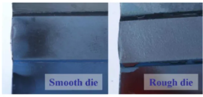
Figure 6: comparison of the oxide surface state after PSCT with rough / smooth dies. Die width 12 mm.ε =0.4,ε =1. −1,
T = 900°C, oxide thickness 50 #m.
Figure 7: cross,section of the samples shown in figure 5, showing the smooth metal (white) – oxide (grey) interface,
whatever the die roughness.
Another possible defect is interface waviness due to tool roughness printing, in particular when rolls are severely worn. Figure 6 shows that the oxide surface, to a large extent, takes the roll roughness, which suggests a certain degree of plasticity of the oxide, but the oxide – metal interface remains smooth (figure 7). This may not be a general conclusion however, certainly dependent (i) on the ratio of the tool roughness to the oxide thickness, and (ii) of the temperature,dependent mechanical properties of the oxide (toughness, oxide,to,metal yield stress ratio). Here again, numerical simulation can contribute in the study of these parameters.
* : $ ,
3.3.a Delamination / spalling
This is another failure mechanism whereby oxide fragments may be spalled off the sample surface; in rolling, such fragments may then be embedded inside the strip surface by the contact pressure.
Figure 8: two examples of delamination. Left: interfacial delamination on the flank of a groove. Right: delamination
within the oxide layer.
In figure 8 (left), bending of the sample in the flank of a grooved die (representing the “roll banding” defect, i.e. peeling of an orthoradial strip of roll oxide) has resulted in a normal, through,thickness crack which has bifurcated along the interface; in such situations, the formation and embedding of a fragment becomes highly probable. The die groove is oriented in the die width direction, equivalent to the rolling direction. Such a crack would thus be longitudinal, contrary to those shown above. Figure 8 (right) shows delamination within the oxide. Lines of pores have occasionally been found in oxide layers, parallel to the interface; they may be the origin of such defects. Yet delamination might also have taken place at the interface, with subsequent re,
oxidation during cooling in imperfectly pure N2.
Here again, fragmentation and embedding of the spalled layer in the next rolling stand is inevitable.
3.3.b Interface instability
In a series of tests devoted to varying strain rate, a sinusoidal interface waviness has been observed at the lowest strain,rate, decreasing and disappearing
as ε increases (figure 9).
Figure 9: Interface waviness without cracking. Strain rate increases from top to bottom (0.1, 1 and 10 s,1).
There is no evidence of any crack / micro,extrusion phenomenon, hence the interpretation by plastic co, deformation instability (see [10] e.g.). It is not sure that this can occur in strip rolling, since it has been
y z
x z
found here only in a low strain rate range; yet it might occur at higher speeds under different conditions (temperature…).
4 THEORETICAL INTERPRETATION
!* "$
The Forge2005® FEM software has been used for this study. Its description can be found in [6,7], together with the added through,thickness crack, opening algorithm (based on a critical fracture stress). Only such cracks are addressed here, although a delamination capability has also been added (Cohesive Zone Modelling approach).
!* # "" $ $ $ " $ $ , 8 9
Figure 10 shows a crack opening simulation in the
PSCT at 1000°C and 1 s,1, with a critical fracture
stress of 200 MPa for the oxide. The oxide and the metal yield stresses are respectively given by:
159 . 0 223 . 0 ) ( . 00299 . 0 . .( 3. ) exp . 69 ) ( ε ε σ = ; (1) 09 . 0 22 . 0 ) . 3 ( . . ) ( 3340 exp . 5 . 8 ) ( ε ε σ = ; (2)
The die,oxide friction factor is +=0.08. The oxide,
metal interface is assumed perfectly adherent.
Figure 10: PSCT FEM modelling and crack formation.
Under these conditions, cracks form either under die edges (figure 10, left) due to the stress singularity, or at asperity tops (figure 10, insert right), but never on flat parts of the die. Looking in more details, with the roughness peak height chosen (3 #m, to be compared with oxide thickness 50 #m), fracture does not occur because of the stress singularity at peak apex, since full penetration of the asperity into the plastic oxide occurs before crack opens. The critical tension is in fact reached later on, when the flow of the underlying metal shears the interface and puts the oxide in tension. In another simulation with a periodic roughness covering the whole die width (Ra = 0.3 #m), cracks appear periodically, but the
wavelength is much larger than the roughness wavelength. Study of the influence of parameters and comparison with experiments are in progress. The effect of friction and shear stress on oblique crack formation (as in figure 5) is also under study.
5 CONCLUSIONS
Experimental results present a number of
deformation and fracture phenomena which occur in oxidized metal / tool contact; their relevance towards interface defects in hot strip rolling has been commented. A first example of application of multi, body FEM to the analysis of the origins of these oxide and interface defects has been presented.
ACKNOWLEDGEMENT
The authors thank ArcelorMittal (Arcelor Research S.A.) for financial support and authorization to publish the results.
REFERENCES
1. G. Vagnard and J. Manenc, Etude de la plasticité du protoxyde de fer et de l’oxyde cuivreux. +* $* *
1* $. LXI 11 (1964) 768,776 (in French).
2. Y.H. Li and C.M. Sellars, ‘Modelling deformation of oxide scales and their effects on interfacial heat transfer and friction during hot steel rolling’, Proceedings of the 2ndConf. Modelling of Metal rolling processes, London (1996) 192,201
3. M. Krzyzanowski and J.H. Beynon, 'Oxide behaviour in
hot rolling', in: $ , + 9 " $ , ed,
J.G. Lenard, Elsevier, Amsterdam (2002) 259,295 4. M.F. Frolish, M. Krzyzanowski, W.M. Rainforth and
J.H. Beynon, 'Oxide scale behaviour on aluminium and steel under hot working conditions', J. Mater. Process. Technol. 177, 1,3 (2006) 36,40
5. M. Schütze, 'Mechanical properties of oxide scales', Oxid. Met. 44, 1,2 (1995) 29,60
6. B. Picqué, %" + $ $2 < 2+ +2 $
, % + 7 1 2 $ 9, PhD
Thesis, Ecole des Mines de Paris (2004)
7. B. Picqué, P.,O. Bouchard, P. Montmitonnet and M. Picard, 'Mechanical behaviour of iron oxide scale: experimental and numerical study',= 260 (2006) 231, 242
8. D.C. Agrawal and R. Raj, 'Measurement of the ultimate shear strength of a metal,ceramic interface', Acta Met. 37, 4 (1989) 1265,1270
9. F. Platteau, G. Lannoo and D. Espinosa, 'Control of strip surface quality during hot rolling', Internal Report, CRM (2007) (personal communication).
10. S.L. Semiatin and H.R. Piehler, 'Formability of sandwich sheet materials in Plane Strain Compression and rolling', Met. Trans. A 10A (1979) 97,107