Science Arts & Métiers (SAM)
is an open access repository that collects the work of Arts et Métiers Institute of
Technology researchers and makes it freely available over the web where possible.
This is an author-deposited version published in: https://sam.ensam.eu
Handle ID: .http://hdl.handle.net/10985/13936
To cite this version :
Laurent CHOUGRANI, Jean-Philippe PERNOT, Philippe VERON, Stéphane ABED - Parts internal structure definition using non-uniform patterned lattice optimization for mass reduction in additive manufacturing - Engineering with Computers p.-- - 2018
Any correspondence concerning this service should be sent to the repository Administrator : [email protected]
Science Arts & Métiers (SAM)
is an open access repository that collects the work of Arts et Métiers ParisTech
researchers and makes it freely available over the web where possible.
This is an author-deposited version published in: https://sam.ensam.eu
Handle ID: .http://hdl.handle.net/10985/13936
To cite this version :
Laurent CHOUGRANI, Jean-Philippe PERNOT, Philippe VERON, Stéphane ABED - Parts internal structure definition using non-uniform patterned lattice optimization for mass reduction in additive manufacturing - Engineering with Computers p.-- - 2018
Any correspondence concerning this service should be sent to the repository Administrator : [email protected]
Parts internal structure definition using non‑uniform patterned lattice
optimization for mass reduction in additive manufacturing
Laurent Chougrani1 · Jean‑Philippe Pernot2 · Philippe Véron2 · Stéphane Abed1
Abstract
Today, being able to generate and produce shapes that fit mechanical and functional requirements and having as low as pos- sible mass is crucial for aerospace and automotive applications. Besides, the rise of new additive manufacturing technologies has widened the possibilities for designing and producing complex shapes and internal structures. However, current models, methods and tools still represent a limitation to that new horizon of printable shapes. This paper addresses the way internal lattice structures can be generated and optimized to reduce the mass of a product. A new framework is introduced that allows the modeling and optimization of non-uniform patterned lattice structures. Using non-uniform structures, additional degrees of freedom are introduced and allow the definition of a wide variety of shapes which can better fit the requirements. First, a non-uniform patterned lattice structure is generated using the results of an initial finite element analysis. This initial structure is then optimized while iteratively removing the beams considered as useless with respect to a user-specified mechanical criteria. At each iteration, the lattice structure is sent to a finite element solver that returns the von Mises stress map used to drive the simplification process. Here, the simulations are performed on the wireframe lattice structures to speed up the optimization loops. Once this process is completed, the final structure is no longer fully patterned, but it is re-organized to reduce the mass while satisfying the mechanical criteria. This approach is illustrated with examples coming from our prototype software.
Keywords Additive manufacturing · 3D modelling · Shape optimization · Lattice structures · Finite element analysis · Mass reduction · Bio-mimicry · Topology optimization · Variable neighborhood search
1 Introduction and motivations
Additive manufacturing (AM) is a relatively new but yet wildly developing industry which changes drastically the way of designing parts. Classical manufacturing processes like milling or machining tend to use physical tools to remove material, extracting the desired structure from it.
Differently, AM processes, especially Laser Beam Melting (LBM or DMLS) and Electron Beam Melting (EBM), tend to start from barely nothing, e.g., metal powders, and build the desired structure out of it, using energy beams (non- material tools) to locally fuse and solidify the powder [1]. Consequently, those new technologies introduce a totally different way of designing, but also new production con- straints and limitations as well as new terminologies. Thus, the notion of lattice structures has become popular, and refer * Laurent Chougrani [email protected] Jean-Philippe Pernot [email protected] Philippe Véron [email protected] Stéphane Abed [email protected]
1 Poly-Shape, Saint-Pierre-du-Perray, France 2
Arts et Métiers, LISPEN, HeSam, Paris, France
to meso-structures made out of inter-connected material beams. Lattice structures are an interesting way for AM to stand out from other production means which cannot gener- ate such complex structures. Even if they still have mechani- cal properties yet to be investigated, lattice structures offer a very promising way for mass reduction. Any industrial sector (e.g., automotive, aerospace) that produces system which move tends to reduce mass for energy consumption purposes [2]. In this context, there is a consensus on the fact that AM is a good candidate for trying new designs and new
numeric methods to produce lightweight products. To reduce the mass of an object, two main ways have been investigated: lattice structure and topology optimization. Both technics lead to complex shapes that can be hard or impossible to manufacture without additive manufacturing. Today, there already exist examples of industrial success stories involv- ing mass reduction through AM. For example, the Thales/ ESA’s deployment mechanism structure for which the mass has been reduced by 5, the costs reduced by 4, the number of components reduced by 10 thanks to a combination of topology optimization and lattice insertion (Fig. 1). Costs for such parts is high, it is still a niche market, essentially for aerospace, automotive and energy industrial fields. Moreo- ver, as the final geometry might be convoluted, the computa- tion time for optimization and the number of iterations can be very high.
In this paper, a new way to generate and optimize lat- tice structures is proposed. The contribution is threefold: (1) a non-uniform lattice structure generation technique is introduced, based on an analogy to crystallography; (2) a new optimization framework is developed to remove lat- tice beams according to mechanical criteria, thus decreas- ing the mass of the structure; (3) a new stress-based crite- rion is used to compare different results from the proposed algorithm. The resulting structure satisfies to user-specified requirements such as mass reduction and rigidity.
Even though researchers and industrials have investigated this research field, there still exist some limitations on the level of freedom the designers have when treating complex parts. The limitations of the existing approaches are dis- cussed in Sect. 2. The proposed framework is introduced in Sect. 3 and the different steps are detailed in Sect. 4. The implementation and the results are presented in Sect. 5. Sec- tion 6 concludes this paper and highlights future perspec- tives of this work.
2 Related work
In recent years, different approaches have been introduced to define rigid, light and printable structures. They can be classified according to three main categories presented in the following sections.
2.1 Topology optimization
Continuous topology is a way of modifying structures to get lightweight parts while optimizing material layout within a given design space with the goal of maximizing the per- formance of the system [3]. Unfortunately, topology opti- mization can be time consuming when the required results needs to be of a high resolution (i.e., high number of voxels). Some other limitations can be discussed depending on the method. For instance, SIMP methods [4] may lead to noisy structures (Fig. 14a) and is the most used method in the industry due to its good computation time performances. Level set and/or BESO/ESO methods [5, 6] can significantly reduce noisy results but need a re-meshing step that can be time consuming in the long run. Topology optimization is also quite a sensitive analysis [7]. However, those limita- tions can be dealt with through seeing that topology results could be interpreted as inter-connected structures, plates or beams. This observation combined with AM capacities has also led to lattice structure studies [8]. In this paper, advantages of both technics are combined in a unified frame- work which optimizes both the topology of the object and a non-uniform patterned lattice structure inserted in it. Such structures (inter-connected beams) can be found in nature in both organic and inorganic structures. Since AM allows to generate such structures with much more resolution than any other manufacturing process, it opens the field of bio- mimicry, i.e bio-inspired designs.
Fig. 1 Satellite solar panel deployment mechanism (courtesy of Thales Alenia Space, ESA and Poly-Shape): a non-additive manufacturing design, b additive manufactur- ing redesign
2.2 Bio‑mimicry
Nature has always been a source of esthetic experience for the mankind and of inspiration for artists and designers [9]. Actually, natural shapes created by natural forces resemble topology optimization results. In 2005, Witzel [10, 11] man- aged to artificially compute a reptile skull through topology optimization. Through this study, they have shown that seek- ing for shape ideas in nature can be valuable (Fig. 2).
This seek for nature comparison and inspiration is called bio-mimicry and it is getting more and more investigated [12]. Some approaches tend to look for patterns that could be used to define lattice structures. Among them, Voronoi diagrams, Delaunay triangulation or fractals are examples of patterns that can be found in tortoise shells, soap bubble agglomera- tions, giraffe’s skin patterns, and many others. Those schemes can be of interest in the AM context because they can be easily generated and propagated through a volume. However, they
Fig. 2 Topology optimization for bio-mimetic simulation of a skel- eton [10, 11]
Fig. 3 a Examples of atomic lattice structures [13]; b insertion of a crystallographic quadratic type lattice within a sphere
represent a difficulty in terms of mechanical models as they require too many elements to be described properly both in terms of geometry and behavior. Non-living structures using lattice can be found in nature, the most famous being crystals [13]. Those lattices have been historically the first to be used in 3D printing for the simple reason that they consist of the duplication of a unitary cell (Fig. 3a)
Patterned lattice often refers to crystallographic struc- tures, replacing atoms with nodes and inter-atomic links with beams (Fig. 3b). Such structure is commonly used due to its symmetry and its defined topology, which allows to quickly compute a mechanical response through some finite element models. Crystallographic lattice are defined in terms of inter-atomic planes. Following this analogy, it is then possible to stretch or compress the distances between those planes to increase the set of accessible shapes (Fig. 4). This can be implemented in different ways
Fig. 4 Example of lattice structures: a elementary cell, b uniform lat- tice deployment, c adaptive lattice deployment
[14]. In this paper, as the structure needs to be optimized with respect to mechanical stress, the distances between the crystallographic planes will be defined so as to fol- low as much as possible the von Mises stress distribution. Thus, high stress density will contract the nearby lattice elements and low stress density will stretch it.
Nevertheless, once an elementary cell has been selected (Fig. 4a), and even though the distances between the crys- tallographic planes can be adjusted, the topology of the structure is fixed. This reduces the degree of freedom in the definition of the lattice. In some case, it would be interesting to let more freedom also in the definition of the topology of the lattice. The framework proposed in this paper allows such local modifications to optimize the topology as well as the geometry of the lattice structures.
2.3 Mechanical model
Another approach to define and optimize lattice structures is to make use of so-called homogenized materials [15]. This consists in looking for a fully filled material with similar properties to the lattice structure that is studied, and use this new material for finite element analysis as a solid material. However, this type of approach owns sev- eral shortcomings. For instance, as this equivalent material is set for a given lattice structure, the lattice topology (i.e., its connectivity matrix) cannot be changed throughout the optimization process (Fig. 5). This would mean that the equivalent material needs to be known for the new topol- ogy, thus leading to the need of an exhaustive equivalent material library. Anyhow, such an equivalent material would smooth the mechanical properties and the influence of the geometric structure.
Furthermore, this method would also not be directly reliable for un-patterned lattice structures, as the equiva- lent material would become a set of equivalent materials connected to each other. Such an approach has not yet been tested in the literature, but would likely lead to some difficulties.
Fig. 5 Example of an optimized lattice structure using homogenized materials and preserving the topology (source Autodesk)
2.4 Non‑uniform patterned lattice
As a conclusion, patterned lattice structures are widespread in current AM processes and are generally preferred to other lattice structures. Unfortunately, there are still gaps between the needs for generating non-uniform patterned lattice structures (Fig. 4c), the actual generation capabili- ties of 3D modelling software (Fig. 4b) and the capacities of modelling the mechanical response of those structures. This paper introduces a new framework to generate an ini- tial non-uniform patterned lattice structure and optimize its topology while removing beams according to mechani- cal criteria. The generation and optimization modules are decoupled in the sense that the optimization could also be performed on a user-specified lattice structure that would not have been generated with our approach. The generation module defines the topology and geometry of the lattice, whereas the optimization module acts on its topology to try to reduce the mass while smoothing the stress distribution. During the optimization loops, the mechanical simulations are performed using a technic that derives from the methods of Alzahrani and Wang [8, 16]. A specific criterion is used to compare the optimality of the resulting structures in terms of stress distribution. The new framework is introduced in Sect. 3 and the details of the different modules are given in Sect. 4. Section 5 discusses the implementation and results.
3 Bio‑inspired optimization framework
Going further into our bio-mimetic comparison, nature’s ultimate issue is minimizing energy consumption. Any organ or body part needs to be fed with nutrients, oxygen and other elements. So, considering that the amount of energy gen- erated per amount of time is fixed for a creature, it needs to distribute this energy among all of its body parts. The percentage of energy distributed to a particular body part depends on the contribution of the body part to the whole body capacity to sustain itself. In this paper, the beams of the lattice can be compared to bones of a skeleton, as their main purpose is to give rigidity to the creature’s body (all other purposes of bones, such as fluid circulation, will be neglected to make it simpler). Inspired by this analysis, an optimization framework is defined, that looks for every beam (comparatively to bones in a skeleton), and sorts the contri- bution of each beam to the structure’s stress contribution to decide if “it should be fed”, meaning that it should remain, or “starve”, meaning that the beam should be suppressed. This is close to what topology optimization does but applied to lattice structures. This principle has been experimented on human bones by manipulating the amount of stress received by a bone and looking at the evolution of the bone’s shape and mass over time [17]. This is based both on Darwin’stheories of evolution [18] and bone structure observations [19]. Those studies infer that in terms of density (that can be related to beams diameter), bones tend to reduce their thickness and re-organize their inner structure as their stress load varies. Of course, such and evolution is done over a relatively long period of time. In this paper, this bio-inspired framework does not modify the beam’s radii, but it will be considered that if the beam contribution is under a certain amount, this beam can directly be removed. In the future, further studies could act on radii evolution, thus, leading to a more accurate bio-inspired method. The proposed optimiza- tion framework consists of different steps presented in Fig. 6
and detailed in the next section. As previously introduced, to explore a wider range of available lattice structures, the inter-reticular planes can be stretched. To do so, a spatial scalar field is needed. von Mises field will be used here to position the crystallographic planes according to the ini- tial stress distribution (Fig. 6b, c). Then, a lattice pattern is selected based on its mechanical behavior and its print- ability (Fig. 6d), it is then propagated within the volume (Fig. 6e). A first calculation is performed to ensure that the limit criterion (von Mises maximum stress) is not already reached (Fig. 6f). Finally, the optimization loop is run until the limit criterion is reached (Fig. 6g). As explained, this loop consists of suppressing beams that contribute the less to the mechanical “stress absorption” (this will be discussed later on) of the structure, according to our bio-mimicry state- ments as well as to a statistical evaluation of the considerate beam contribution among the whole beam population. This
Fig. 6 Framework for patterned lattice structure optimization
process stops when a certain limit is reached (here, a von Mises maximum value) and the structure is saved.
4 Algorithms and methods
4.1 Crystallographic plane definition
The planes that define the cell’s boundaries can be manip- ulated in such ways that their relative positions can vary non-uniformly in three dimensions. Thus, new designs can be tackled with a wider range of lattice fibers and possible curvature evolutions (Figs. 4, 7). To drive the position of the crystallographic planes, the von Mises scalar field is used as an attractive or repulsive field. Therefore, the more the von Mises stress is important, the more the distance between the planes is small. Of course, many other distribution laws could be defined and used. Figure 7b, c shows two distribu- tions which can be obtained through that proposed method.
4.2 Cell topology definition
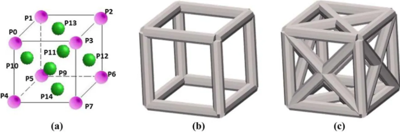
Lattice can be created out of crystallographic structures by replacing atoms with nodes and atom links with beams. Thus, several patterns can be imagined and compared in terms of mechanical behavior. To quickly illustrate the way an initial pattern can be identified, results for two extreme cases are presented: the so-called grid pattern (Fig. 8b) and face-centered cubic (FCC) pattern (Fig. 8c).
The topology of the grid pattern (resp. FCC pattern) can be encoded using a connectivity matrix CGrid (resp. CFCC) coming from the Graph theory [20]. Considering a set of
Fig. 7 Insertion of lattice structure: a von Mises field. b Uniform lat- tice insertion. c Non-uniform lattice insertion
Grid FCC FCC/grid ratio Max display (mm) 4.98E−03 5.26E−04 0.1056
Max VM (MPa) 27.8 5.01 0.1802
Volume (Cmm) 1.04E−07 2.28E−07 2.192
n
n
⎢
Fig. 8 Cell topology definition: a FCC crystallographic atoms and links. The grid pattern only uses corner nodes P0–P7 (b), and the FCC pat- tern uses both corner and centered nodes P0–P14 (c)
(n + 1) nodes P0–Pn , one can create a set of C2 potential
beams, denoted , ranging from B00 to Bnn and containing all
the combinations of node connections. The effective lattice structure does not necessarily contain all the elements of (it generally does not). An element of contained in is said to be “activated”. Thus, the elements cij of the con-
nectivity matrix of dimension ((n + 1) × C2) are defined
as stated in the following equation: (
1 if Bij ∈
been applied on a unitary cell of size 5 mm and have been loaded with a shear stress of 10 N. The radius of the beams is 1mm. Results are displayed in Table 1.
One can notice that the FCC pattern offers a good com- promise between a great reduction of the max displacement (about ten times less) and a relatively low increase of the mass (about two times more). So, even if our objective is to minimize as much as possible the mass, starting with a FCC-based lattice structure is a good idea. Such a choice Cij = 0 if B
ij ∉
(1) can allow a great variety of orientations and a high pos- sibility of combinations while securing the rigidity aspects. Even if the Graph theory also allows for −1 values, it is not
needed for this purpose. Using this equation, the following two elementary matrices CGrid and CFCC can be obtained and
used to define the whole lattice structure by looping through the volume. For the sake of readability, rows containing only 0 are removed.
1 1 0 0 0 0 0 0 0 0 0 0 0 0 0
Anyhow, since our optimization process removes beams, it can converge to a solution close to the one that would have been obtained while using the Grid pattern. Finally, one can mention other researches that follow mechanical criteria to insert multiple cell types at different places within the structure [21]. In this case, the difficulty lies on the inter- connectivity between cells. Even if this can be an interesting ⎡ ⎤ way of improving computation times, it will not be studied ⎢ 1 0 0 1 0 0 0 0 0 0 0 0 0 0 0 ⎢
⎢1 0 0 0 1 0 0 0 0 0 0 0 0 0 0 ⎢
⎢0 1 1 0 0 0 0 0 0 0 0 0 0 0 0 ⎢ in this paper.
⎢ ⎢
4.3 Lattice deployment
⎢ 0 1 0 0 0 1 0 0 0 0 0 0 0 0 0 ⎢
⎢ 0 0 1 1 0 0 0 0 0 0 0 0 0 0 0 ⎢ Given the bounding box of the volume to fill in with cells,
CGrid = ⎢ ⎢ (2)
0 0 1 0 0 0 1 0 0 0 0 0 0 0 0 ⎢ ⎢ 0 0 0 1 0 0 0 1 0 0 0 0 0 0 0 ⎢
⎢ 0 0 0 0 1 1 0 0 0 0 0 0 0 0 0 ⎢ the lattice is fully known through both the number of needed cells per dimension and the deformation fields. Thus, two
⎢ ⎢ cases can be distinguished:
⎢ 0 0 0 0 0 1 1 0 0 0 0 0 0 0 0 ⎢ ⎢ 0 0 0 0 0 1 1 0 0 0 0 0 0 0 0 ⎢
⎢ ⎢
⎣ 0 0 0 0 0 0 1 1 0 0 0 0 0 0 0
Using our approach, the topology of the initial lattice structure is defined by the connectivity matrix whereas the geometry of the lattice structure is given by the position of the crystallographic planes. Of course, the choice of a pat- tern impacts the mechanical behavior of the entire structure. To go further in this understanding, those two patterns have
Table 1 Estimated result values for both structures (for a same given
i j,n
N – Uniform lattice In this case, a simple loop based on
the (dx, dy, dz) unit cell’s dimensions, and the (X, Y, Z) bounding box’s dimensions is used. The user gives the number Ni of cells per axis i ∈ {x, y, z} through which the unit cell’s dimensions can be computed:
dx = X ⎧ Nx
4.4 Optimization loop
In this paper, the mass of the structure is reduced step by step while removing beams of an initially patterned lattice as defined in Sect. 4.2. The removal is performed according to a mechanical criterion, i.e., the distribution of von Mises stress. Manufacturing constraints are not fully addressed here, as the ⎢dy = Y
(3) FCC pattern is printable regarding its stretched dimensions ⎨ Ny
⎢dz = Z
⎩ Nz
– Non-uniform lattice Here, a deformation field is needed to drive the crystallographic plane stretching. In the proposed approach, Bezier curves are used to define this deformation field along the three directions of the bounding box. For a given direction of the bounding box i ∈ {x, y, z}, the Bézier curve is defined as follows [22]:
ni
in x, y and z. Further work would be needed to consider this printability constraints. The method is discussed in the next sections. The overall idea is to sequentially run a FE analysis (Sect. 4.4.1) to define the beams with a low stress, and then remove those beams (Sect. 4.4.2). The removal step is per- formed while following an optimization criterion (Sect. 4.4.3). Finally, the simplified structure is cleaned to remove self-hang- ing beams (Sect. 4.4.4).
4.4.1 FE analysis
P (t) =� B (t) × s , ∀t ∈ [0;1] (4) Once the lattice structure is generated and a load case is
i j
j=0
With (ni + 1) control points positioned with respect to
the local maximums of the von Mises stress that have been computed before. Those control points act like attractors on the curve, contracting planes around posi- tions of high von Mises stress. The number of control points can be adjusted depending on the stress distri- bution. Adding control points would result in a more contracted lattice structure, even though their number generally remains below four; otherwise, other control curves could be useful such as NURBS. The initial and final control points are positioned on the boundary of the bounding box to cover the entire space. Finally, the user specifies the number Ni of cells per direction which
is used to position the crystallographic planes accord- ing to points Pi(tk ) of the Bezier curve located using a
uniform law:
1
defined, the simulation model is sent to a finite element solver that returns the average von Mises stress in each beam. This stress distribution provides the contribution of each beam to the stress absorption. Here, the beams are modeled as a wire- frame structure (1D elements) to reduce computation times. This simplification brings up some limitations that are not discussed in this paper.
4.4.2 Beam deletion
To optimize the topology of the lattice structure, it is needed to understand how the structure behaves when beams are removed. For that matter, one can look at the structure in terms of inter-connected unit cells. This concept can adapt to any type of pattern, so this discussion will address a random beam neighborhood to remain general. It will only depend on the previously introduced connectivity matrix C. A lattice node is defined as a spatial point where beams interconnect with each other. It can be represented in terms of its neighborhood tk = k × Δi, ∀k ∈ {0, … , Ni} and Δi =
i
(5) such as in Fig. 9 where the different loads are represented per beam [8].
Since the volume to fill in is defined by a triangle mesh whose shape may be complex, a trimming step is required to trim the cells which go outside. Thus, once the planes have been positioned using one of the two technics, it is possible to sort out the intersections between the planes and the triangles. Cells are then created at the intersection between six planes, they are
Using the energy conservation principle, assuming the hypotheses of linear static mechanics and that beams have the same radii, one can go back to a simplified approximation of the virtual work principle. In 2D, one can write that the iso- lated system is such as (Fig. 9):
⎧∑5 i
i=0 f1 = 0
filled in with a given pattern (Sect. 4.2) and potentially ⎢∑5 f i = 0 (6)
trimmed if they are intersecting with triangles. Follow- ⎨ ⎢∑i=0 2 5 i
ing this strategy, it is ensured that every beam is inside the triangle mesh.
i=0 f3 = 0
j
circulating through another node. Then, through conserva- tion of energy, the total amount of redirected stress needs to be of 100% and the local redirected amount of stress cannot overcome the deleted amount of stress. This statement leads to the following Eq. 9:
n
�
e(i) = 1 with e(i) ∈ [−1;1].
i=0
(9)
Fig. 9 Example of a node neighborhood and associated loads [8] For each beam removal, Eq. 6 leads to a new stress reparti- tion within the cells of the whole structure. The way the stress distribution evolves strongly relies on the lattice pat- tern and the load case. In the proposed approach, only low- stressed beams are removed so that the amount of stress that was circulating within the suppressed beam is redirected into the other surrounding beams. Consequently, the stress levels of the surrounding beams rise.
Let 8(i) be the variation of stress on node connected to a removed beam. Then, each node in the remaining structure will see its stress level varying and become f �(i) such that Eq. 6 still remains and becomes :
Thus, c(i) represents the percentage of stress that each remaining beam will have to sustain. This phenomenon leads to stress homogenization within the structure. It appears clearly that removing one low-stressed beam will not highly disturb the structure. However, either removing one high- stressed beam or too many low-stressed beams could lead to a high amount of stress redistribution, which could lead to the structure disruption.
It is then chosen to remove beams according to a criterion that will select a certain amount of elements based on their stress level and remove them. This criterion will not be dis- cussed here, and so is the overall algorithm.
4.4.3 Optimization criterion
After the iterative removal process, a lattice structure is con- sidered as optimal if all the remaining beams are at the same level of the von Mises stress (this level being defined by the user as the von Mises limit criterion). On that particular mat- ter, as 1D beams are used, one could argue that von Mises criterion does not apply. The finite element solver used:
⎧∑n �(i) Cast3m [23], proposes the same operator called “VMIS” to
∀k ∈ {0, … , 5} ⎢ i=0 f0 = 0
... (7) compute an equivalent constraint criterion, no matter if ele-
⎨∑n �(i) ments are 3D, 2D or 1D. In the 1D case (beams) the criterion
⎢ i=0 fk = 0
⎩ is computed such as:
f(
EFFX 2 2 2 2 (10)
VMIS =
SECT + MOMX TORS ∗ DX + MOMY INRY ∗ DY + MOMZ INRZ ∗ DZ
With n the number of beams on a neighborhood. This stands for a 3D structure (i.e., 3D neighborhood). Then, for each node in the remaining structure:
with respect to the Cast3m notations which can be found in [23, 24]. In the proposed approach, this stress level directly corresponds to a user-specified limit. From that point, one can define a scalar value A that will be used as a performance
f �(i) i (8)
j = fj + c(i) × 8(i),
where ë(i) can be discussed regarding the selected pattern (the different incoming angles, radius of each beams, and the applied load case). Thus, its value will not be defined here. c(i) represents the percentage of stress that was circulating
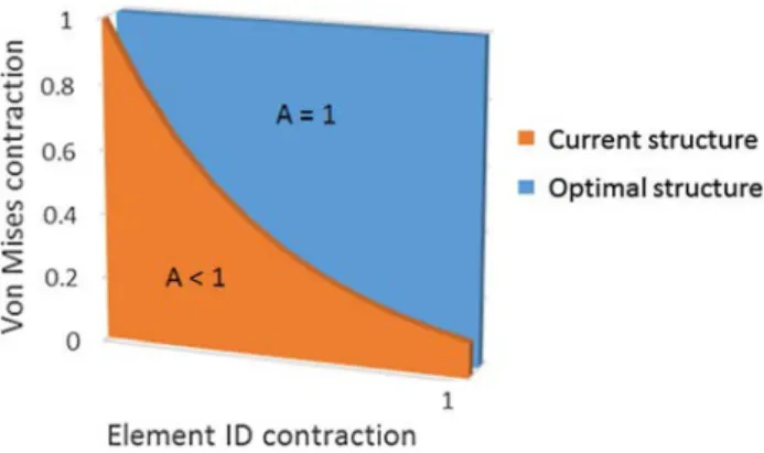
indicator for the algorithm. This scalar value is the area under the curve representing the distribution of the stress level in the lattice structure (Fig. 10). For an optimal structure, i.e., a structure for which the remaining beams are at the same level of the von Mises stress, this area is simply equal to:
Fig. 10 Rescaled distribution of the stress level for the current and optimal structures
could use a criterion that mimics those used in topology optimization, i.e., based on either a level set method or a homogenization of the compliance matrix [25]. However, an adaptation has to be performed to use this criterion on a lattice structure. A result of such a method on 3D ele- ments is discussed in Sect. 5. In this paper, a statistical data criterion are used to sort low-stressed beams. To be effec- tive, the adopted criterion must be acceptable in terms of computation times and lead to a non-degenerated structure, i.e., a structure which can still sustain the load case. Here, the so-called cut criterion Ccut corresponds to the difference
between the von Mises mean stress MVM and the von Mises
stress standard deviation SDVM:
Ccut = MVM − SDVM (12)
where NB is the number of beams and LVM is the limit von
Mises criterion. To compare lattice structures composed of a different number of beams, it is preferable to rescale the von Mises stress and the number of beams over the interval [0; 1] as shown in Fig. 10.
This criterion helps evaluating how much the stress is equally distributed in the lattice structure during the opti- mization loop. Consequently, the closest A is from 1, the closest the structure is to the optimal one (Fig. 10). Thus, at each step of the optimization process, knowing the stress repartition in the structure, one can remove the lattice ele- ments that are unnecessary for the structure rigidity. How- ever, removing the elements one by one would lead to high computation times making it non-suitable for industrial applications. It is thus needed to use a criterion to remove sets of beams and not the beams one by one. Ideally, one
Using a statistical approach leads to a non-absolute crite- rion, each beam gets a notation relatively to other beams and to the maximum stress required. It means that even if the absolute simulated stress values deviate from the experiment, it is still accurate in terms of relative stress distribution, and one can still sort out which beams need to be removed. Moreover, since wireframe simulation models are far faster to compute than 3D models, this method can compute dense lattice structures quickly and as the criterion is relative, one only needs to calibrate a safety coefficient based on expert knowledge to stop the optimization process. Then, if mandatory, a 3D finite element analysis can be used to get more accurate results. The proposed criterion gives both the position of the beam within the whole population in term of von Mises stress (through standard deviation) and its distance to mean stress. For an homogeneous popu- lation of beams, this leads to a removal of less than 10% of
Fig. 11 Initial A criterion for both classic and stretched lattice structures (Fig. 7), von Mises stress value per element sorted form highest to low- est. a Uniform lattice, b non-uniform lattice
the total population at each iteration [26]. Furthermore, the number of beams that will be removed is proportional to the total number of beams remaining within the structure. This allows to auto-regulate the beam population. This process directly uses the von Mises (approximated von Mises due to wireframe models) distribution. It affects the connectiv- ity matrix C and the final lattice structure is not anymore a pattern. Figure 11 illustrates two stress distributions for the two crystallographic plane arrangements of Fig. 7. A pure shear load case of 10 N is applied at the extremity and no beams are removed. Even for the same FCC elemen- tary cells, and for the same number of beam elements, the stress distribution can vary depending on how the crystal- lographic are distributed. Figure 11b shows that the non- uniform adaptive lattice has a more homogeneous stress repartition (see decile of von Mises stress). Applying our performance criterion would lead to a value A = 0.027 for the uniform lattice and A = 0.030 for the non-uniform lat- tice (11% gain) (Fig. 7).
4.4.4 Cleaning
Once the beams have been iteratively removed and the stop criterion has been reached, self-hanging beams are removed. They correspond to beams that sustain no stress. Thus, beams that have a stress level of 0 MPa (±c) are removed. As a remark, one can understand that as 1D beams are used, the stress level of a beam Bij is computed as:
1
removing of unnecessary beams can then not be based on their stress level but on the fact that one of their nodes is not stressed. This issue could be address more effectively using the C matrix to sort out overhanging beams (nodes with only one beam connected) and delete them.
5 Implementation and results
The proposed framework has been implanted on our proto- type platform developed in C# and based on MVVM WPF technology. It creates non-uniform patterned lattice struc- tures that are then optimized using Cast3m as a finite ele- ment solver, integrated in our optimization loop. To validate the proposed approach, the case study of Fig. 7 will be used. A load case of 10 N perpendicular to the structure main axis is applied at the extremity, and the user-specified maxi- mum von Mises criterion LVM is set to 40 MPa. After few
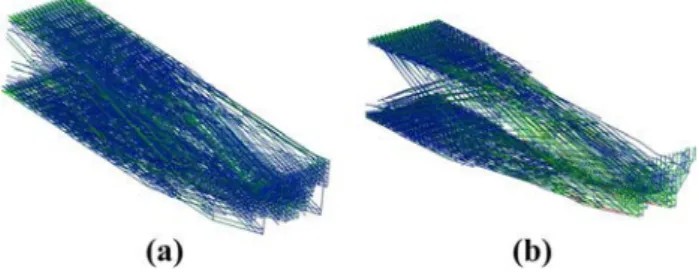
iterations, the structure has evolved towards an optimized structure that suits the technical requirements and allows an effective mass reduction. The stress has been homogenized within the structure that is not degenerated (Figs. 13, 14).
VMIS(Bij) =
2 ⋅ (VMIS(Ni) + VMIS(Nj))
(13) Then, for an overhanging beam, the stress level on one node would be 0, and on the other node would it have a certain
value, leading to a beam stress level superior to 0. The Fig. 13 Isometric views of the final structures. a Uniform lattice. b non-uniform lattice
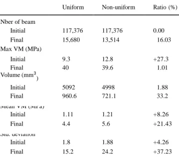
Table 2 Comparison of the maximum stress and associated volume for the initial/final and uniform/non-uniform structures
Uniform Non-uniform Ratio (%) Nber of beam Initial 117,376 117,376 0.00 Final 15,680 13,514 16.03 Max VM (MPa) Initial 9.3 12.8 +27.3 Final 40 39.6 1.01 Volume (mm3 ) Initial 5092 4998 1.88 Final 960.6 721.1 33.2 Mean VM (MPa) Initial 1.11 1.21 +8.26 Final 4.4 5.6 +21.43 Std. deviation Initial 1.8 1.88 +4.26 Final 15.2 24.2 +37.23
Fig. 14 Comparison between a SIMP continuous topology, b non- uniform lattice structure and c uniform lattice structure
Here, our performance indicator is A = 0.11 for the uniform lattice and A = 0.14 for the non-uniform one with a relative gain of 27% (Fig. 12). This illustrates a better von Mises stress distribution throughout the beam population.
As one can see comparing Figs. 11, 12, the optimization process tends to smooth the curve of stress repartition, illus- trating the homogenization process. Figure 12 also contains the decile repartition of von Mises stress for the uniform and non-uniform lattice structures. Comparing Figs. 11,
12 shows that through the overall diminution of beam ele- ments, the stress level in each of those elements has raised
up toward the user-specified von Mises limit criteria. It cor- responds to the homogenization phenomenon.
Figure 13 shows that the denser parts of the resulting structures are located on the upper and lower planes near the fixations, and that the center area’s density has been significantly lowered. Such a behavior is consistent with what usual optimization leads to, like IPN structures for example.
Table 2 gives output values, the ratio column provides the percentage of relative values from non-uniform to uniform structure. The gain from initial to final volume is of 85.6% for the non-uniform structure and 81.1% for the uniform, showing that with the same initial number of beam, their spatial repartition is of importance for the optimization pro- cess. Finally, Table 2 compares all the results and sorts the obtained gain for each value (gain from non-uniform to uni- form lattices). Mass was the main objective of the optimiza- tion process and can be improved, for this test case, by 33% only by stretching the lattice structure. One can also see that mean stress is higher (and so closer to the limit criterion) when using a non-uniform lattice.
Figure 12 shows that the stress distribution is better than for the initial lattice structure (Fig. 11) as most of the beams have a stress level under [mean stress + standard devia- tion]. The performance indicator A is still smaller than 1, but its value has been multiplied by a factor 5 compared to the initial structure (from 0.03 to 0.14). In this work, only the removal of beams was authorized, but allowing other transformations could lead to an even better distribution and could help raising the A value further more. Among those foreseen transformations, one could cite beam radius evolu- tion, beam switching and beam to plate transformation.
To further analyze the results, a classic topology optimi- zation based on SIMP method has been run on the initial fulfilled volume. The results are shown in Fig. 14. One can see that the general shape of our optimized lattice structure tends to keep material in the same place as the classic topol- ogy optimization does.
Finally, one can see that the way the crystallographic planes are distributed is important for the optimization pro- cess. Thus, alternative plane distribution rules still have to be studied so as to improve even more the performance indica- tor and reduce the mass.
6 Conclusions and future works
In this paper, a non-uniform patterned lattice structure opti- mization framework has been proposed and validated. The optimization process starts with an initially non-uniform structure and iteratively removes beams according to the von Mises stress distribution within the whole structure. At
the end, the structure becomes un-patterned, the stress is bet- ter distributed and the mass is reduced. Compared to Fig. 2, results of Fig. 14a, b illustrate that the proposed approach also tends to generate nature-like structures.
A first remark one would have would be to use directly the constraints tensor field instead of the von Mises scalar field. This would allow to differentiate tension from com- pression, and to enable a better space redistribution of the crystallographic planes. For the sake of simplicity, and as a first attempt, von Mises criterion has been chosen precisely for being a simple scalar instead of nine scalars embedded in a tensor, but future works will extend this particular point. Such method has already been tested and has shown interest- ing results [27].
Similarly, using 1D finite elements does not allow to go up to a complete optimization, but to get a lattice shape con- taining as less beams as possible. Then, it is necessary to run a 3D finite element calculation to ensure that the tech- nical requirements are met. This is an alternative to com- mon approaches that still needs to be improved but allows to change lattice topology during optimization contrary to homogenized material methods (Fig. 5). This widens the design possibilities.
Finally, through Figs. 12, 14 one can see that there is still potential for pushing the von Mises front up to the limit criterion and get the A criterion as close as possible to 1. As already said, this improvement could be done by allow- ing more transformations. Instead of only removing beams, beams could be switched, new beams could be added, beam’s radii could be changed and so on [26]. Moreover, Fig. 14 and Table 2 illustrate that working on non-uniformly distributed crystallographic planes improves significantly the performance indicator A and leads to a significant mass reduction when compared to a uniform lattice structure. Thus, the way those planes are located throughout space still needs to be thought. It can be seen as a pre-optimi- zation process. This method could give access to a wider range of reachable geometries and topologies for complex structures, improving material space repartition in a con- tinuous topology-related fashion, thus reducing significantly the mass of systems through lattice structures.
Finally, the comparison between the adopted simulation models and the corresponding experiments was not tackled and still remains an issue for this method to be efficient.
References
1. Gebhardt A (2018) Understanding additive manufacturing. Hanser Publishers, Munich
2. Dragan Kreculj BR (2013) Review of impact damages model-ling in laminated composite aircraft structures. Tehnicki vjesnik Pregled modeliranja udarnih ostecenja u laminatnim kompozitnim konstrukcijama letjelica 20(3):485–495
3. Duysinx P, Bendsoe MP (1998) Topology optimization of con-tinuum structures with local stress constraints. Numer Methods Eng 43(8):1453–1478
4. Zhou X, Chen L, Huang Z (2017) The simp-srv method for stiff-ness topology optimization of continuum structures, CAD Center, School of Mechanical Science and Engineering, HuaZhong Uni-versity of Science and Technology, Wuhan, Hubei, 430074. P.R, China
5. Allaire G, Dapogny C, Frey P (2011) Topology and geometry opti-mization of elastic structures by exact deformation of simplicial mesh. Ecole polytechnique centre de mathématiques appliquées UMR CNRS 7641
6. Huang X, Xie YM (2010) A further review of ESO type methods for topology optimization. Struct Multidiscip Optim 41:671–683 7. Deng X, Wang Y, Yan J, Liu T, Wang S (2016) Topology
optimiza-tion of total femur structure: applicaoptimiza-tion of parametrized level set method under geometric constraints. J Mech Design 138:011402 8. Wang HV (2005) A unit cell approach for lightweight structure
and compliant mechanism. Ph.D. thesis, Georgia Institute Of Technology
9. Arnarson PO (2011) Biomimicry. School: reykjavik univ.
http://olafurandri.com/nyti/papers2011/Biomimicry%20-%20 P%C3%A9tur%20%C3%96rn%20Arnarson.pdf
10. Witzel U, Preuschoft H (2005) Finite-element model construction for the virtual synthesis of the skulls in vertebrates: case study of diplodocus. The Anatomical Reord, special issue: Finite Element Analysis in Vertebrate. Biomechanics 283(2):391–401
11. Witzel U, Preuschoft H (2014) International design conference. Dubrovnik
12. Avsec M (2016) Biomimicry and 3d printing. Third Annual Ben-esch 3D printing conference spotlights biomimicry, startups, and legal issues in additive manufacturing
13. Rousseau J, Gibaud A (2007) Cristallographie gTomTtrique et radiocristallographie. Dunod (ISBN: 978-2-10-050198-4) 14. Hadi A, Vignat F, Villeneuve F (2015) Design configurations and
creation of lattice structures for metallic additive manufacturing. 14eme Colloque National AIP PRIMECA. La Plagne
15. Suard M, Villeneuve DR, Vignat F (2015) characterization and optimization of lattice structures made by electron beam melting. Ph.D. thesis, Grenoble INP, France, Grenoble
16. Alzahrani M, Choi SK, Rosen DW (2015) Design of truss-like cellular structures using relative density mapping method. Mater Des 85:349–360
17. Howell JA (2005) an experimental study of the effect of stress and strain on bone development. Anat Rec 13:349–360
18. Darwin C (1859) The origin of species by mean of natural selec-tion. John Murray, London
19. Howell JA (1986) The law of bone remodeling. translation of the German, 1892 edn. Springer, Heidelberg (1986)
20. Bondy JA, Murty USR (1982) Graph theory with applications. Department of Combinatorics and Optimization. University of Waterloo, Ontario, Canada. Springer, New York (ISBN: O-444-19451-7)
21. Watts DM, Hague RJ (2006) Exploiting the design freedom of RM, Rapid Manufacturing Research Group. Loughborough University, Wolfson School of Mechanical and Manufacturing Engineering
22. Piegl L (1995) The NURBS Book. Elseyier Science Publishing Co, Amsterdam (1995) (ISBN: 978-3-642-97385-7)
23. CEA (2018) Cast3m general notice. http://www-cast3m.cea.fr/ index.php
24. CEA (2018) Cast3m, up to date von mises notice and web-site. http://www-cast3m.cea.fr/index.php?page=notices¬ic e=VMIS
25. Allaire G (2006) Conception optimale de structures, vol 58. Springer, Berlin, Heidelberg (2006)
26. Teufelhart S, Reinhart G (2012) optimization of strut diameters in lattice structures. Solid Freeform Fabrication Symposium. Pro-ceedings: SFF Symposium—an additive manufacturing confer-ence, held at the University of Texas in Austin on August 6–8, 2012. Austin, pp 719–733
27. Tam KMM, Coleman JR, Fine NW, Mueller CT (2015) Stress line additive manufacturing (slam) for 2.5-d shells. In: Proceedings of the International Association for Shell and Spatial Structures (IASS) Symposium, Amsterdam Future Visions

![Fig. 3 a Examples of atomic lattice structures [13]; b insertion of a crystallographic quadratic type lattice within a sphere](https://thumb-eu.123doks.com/thumbv2/123doknet/7426870.219478/5.892.82.430.454.720/examples-atomic-lattice-structures-insertion-crystallographic-quadratic-lattice.webp)

![Fig. 9 Example of a node neighborhood and associated loads [8]](https://thumb-eu.123doks.com/thumbv2/123doknet/7426870.219478/10.892.149.363.83.332/fig-example-node-neighborhood-associated-loads.webp)