Science Arts & Métiers (SAM)
is an open access repository that collects the work of Arts et Métiers Institute of Technology researchers and makes it freely available over the web where possible.
This is an author-deposited version published in: https://sam.ensam.eu
Handle ID: .http://hdl.handle.net/10985/19175
To cite this version :
George CHATZIGEORGIOU, Fodil MERAGHNI, Nicolas CHARALAMBAKIS, Adil BENAARBIA -Multiscale modeling accounting for inelastic mechanisms of fuzzy fiber composites with straight or wavy carbon nanotubes - International Journal of Solids and Structures - Vol. 202, p.39-57 - 2020
Multiscale modeling accounting for inelastic
mechanisms of fuzzy fiber composites with straight or
wavy carbon nanotubes
George Chatzigeorgioua,˚, Fodil Meraghnia, Nicolas Charalambakisb,
Adil Benaarbiaa
a
Arts et Metiers Institute of Technology, CNRS, Université de Lorraine, LEM3-UMR 7239, F-57070 Metz, France
b
Department of Civil Engineering, Aristotle University of Thessaloniki and Center for Research and Development of Advanced Materials CERDAM, AUTH-Texas A&M, GR
54124, Thessaloniki, Greece
Abstract
This paper proposes a micromechanical approach aimed at identifying the response of unidirectional fuzzy fiber composites undergoing inelastic fields. Fuzzy fibers are reinforcement fibers coated with radially aligned straight or wavy carbon nanotubes grown through chemical deposition process (PVD or CVD). Due to this nature, the composite with fuzzy fibers is described by three scales: i) the microscale consisting of carbon nanotubes and their surrounding matrix, ii) the mesoscale containing the fiber, the nanocom-posite and the matrix, and iii) the macroscale related to the overall fuzzy fiber composite. The developed framework considers for the mesoscopic scale an analytical formulation, based on the composite cylinders assem-blage (CCA) method, combining the principles of the Transformation Field
˚Corresponding author.
Email addresses: georges.chatzigeorgiou@ensam.eu(George Chatzigeorgiou), fodil.meraghni@ensam.eu(Fodil Meraghni), charalam@civil.auth.gr
Analysis (TFA) technique. A numerical example that includes comparisons with full field homogenization strategies confirms the accuracy of the frame-work to predict the overall response, as well as the average local fields of the constituents.
Keywords: fuzzy fiber; unidirectional composites; composite cylinders assemblage; effective properties; inelastic fields.
1. Introduction
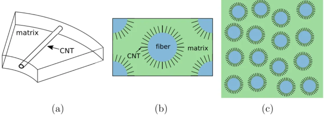
The exceptional mechanical and physical properties of carbon nanotubes (CNTs) determined experimentally or estimated (Shen and Li, 2004; Xiao et al., 2005; Batra and Sears, 2007), encouraged the extensive research pro-duction for the development of CNT-reinforced composites. In this spirit, composites including fuzzy fibers, i.e. carbon, glass or ceramic fibers coated with CNTs (Figure 1), have been recently the subject of a plethora of pub-lications due to the increasing interest for apppub-lications in aerospace, energy, infrastructure and health monitoring, among other areas (Sager et al., 2009; Sebastian et al., 2014; Hart et al., 2017).
Several modeling efforts have been conducted the last decade to identify different types of behavior of such composites, namely elastic (Chatzigeorgiou et al., 2011; Kundalwal and Ray, 2011, 2012; Chatzigeorgiou et al., 2012b), thermoelastic (Kundalwal and Ray, 2014; Kundalwal and Meguid, 2015) and electromechanical (Seidel et al., 2014; Dhala and Ray, 2015; Ren et al., 2015). Since the fibers are coated with the nanotubes, the interlayer (usually called nanocomposite) can be seen as a composite consisting of carbon nanotubes in radial arrangement on the surface of fibers inside the matrix. Thus, the
Figure 1: A single fuzzy fiber with densely-packed CNTs on the surface. Reprinted by permission from Springer Nature: Multiscale Modeling of Multifunctional Fuzzy Fibers based on Multi-Walled Carbon Nanotubes, in ”Modeling of Carbon Nanotubes, Graphene and their Composites”, Tserpes, K. I., Silvestre, N. P. (Eds.), Vol. 188 of Springer Series in Materials Science, by Seidel G.D., Chatzigeorgiou G., Ren X., Lagoudas D.C., 2014.
nanocomposite can be treated as a separate heterogeneous material with cylindrically orthotropic response. As a consequence, the fuzzy fiber can be studied as two concentric cylinders (fiber and nanocomposite) embedded into the matrix, with the coating layer being a heterogeneous medium. Thus, the total composite is a three scale medium, with micro- (CNTs embedded in matrix), meso- (fuzzy fiber embedded in matrix) and macro- (composite) scales (Figure 2).
Experimental and theoretical studies on the interphase strength between the matrix and the reinforcement are an extensive research topic. The back-ground for developing a theory of fiber composites with enhanced fibers was the development of elasticity solutions for heterogeneous cylindrical fibers and the determination of the elastic deformation of composite cylinders with cylindrically orthotropic layers. The fundamental solutions for fibers
embed-matrix
CNT
(a) (b) (c)
Figure 2: Microscopic (a), mesoscopic (b) and macroscopic (c) scales of a fuzzy fiber composite material.
ded in a matrix by Hashin and Rosen (1964); Christensen and Lo (1979); Av-ery and Herakovich (1986); Hashin (1990) allow for predicting effective elastic and thermoelastic properties. The composite cylinder assemblage (CCA) ap-proach, introduced by Hashin and Rosen (1964), remains a powerful tool for the prediction of effective properties of fiber composites. The three phases model, consisting of a cylindrically orthotropic cylinder, a coating with sev-eral degrees of anisotropy and a matrix, has been studied and its effective thermoelastic behavior has been analyzed (Chen et al., 1990; Hashin, 1990). The presence of a cylindrically orthotropic interphase layer in a fiber com-posite has been introduced by Honjo (2007). Explicit expressions for stress and displacements in a multilayered hollow cylinder with orthotropic elastic layers have been provided by Tsukrov and Drach (2010). The special case of a fiber composite in which each fiber is surrounded by cylindrically orthotropic layers has been investigated by Tsukrov et al. (2012) in order to analyze the influence of anisotropy and inhomogeneity of the layers on the fibers. In Chatzigeorgiou et al. (2011), a two step asymptotic expansion
homogeniza-tion scheme in cylindrical (for the layer) and Cartesian coordinates has been presented. Chatzigeorgiou et al. (2012a) proposed the approximate locally periodic homogenization for fiber composites with cylindrical geometry. In Chatzigeorgiou et al. (2012b), the same problem has been investigated via the CCA method. In the latter article, the reinforced interphase is assumed to behave as a transversely isotropic medium with the axis of symmetry par-allel to the axis of CNTs. Kundalwal and Ray (2011) have analyzed the fuzzy fiber composite response using Mori-Tanaka, by substituting the inter-phase layer with an equivalent transversely isotropic medium with the axis of symmetry parallel to the axis of the fiber. The same authors have pro-posed an alternative approach based on the method of cells (Kundalwal and Ray, 2012) to investigate the influence of the CNTs waviness on the overall response of the fuzzy fiber composites (Kundalwal and Ray, 2014).
The present paper proposes a micromechanical approach for unidirec-tional fuzzy fiber composites accounting for the presence of inelastic fields. The fuzzy fibers are considered to be fibers coated with CNTs, which are ei-ther straight or wavy microfibers. The developed scheme is based on the CCA method, adopted for the cylindrically orthotropic nature of the nanocompos-ite layer that surrounds the actual fiber. Accounting for nonlinear mecha-nisms in analytical micromechanical approaches is a task studied by many authors in the literature. A popular approach addressing inelastic fields in composites is the well known transformation field analysis (TFA) by Dvorak (1992); Dvorak and Benveniste (1992); Michel and Suquet (2003). Accord-ing to this approach, the stress or the strain is split into elastic and inelas-tic parts. In Chatzigeorgiou and Meraghni (2019), a mean field multiscale
approach for composites reinforced by coated fibers exhibiting elastic and inelastic strain has been presented. It follows the TFA framework and per-forms two methodologies; one is based on classical Eshelby-type methods like Mori-Tanaka, while the second is based on the Composite Cylinders/Spheres Assemblage homogenization strategy. The TFA approach is extensively de-ployed in the present work for accounting the inelastic fields applied to the fuzzy fiber composite.
The organization of the paper is as follows: In Section 2, the problem under consideration is described, including a general description of the fuzzy fiber composites, the assumptions on the material symmetries of the phases and the equations of the problem. Section 3 presents the composite cylinders assemblage methodology for the mesoscale problem. In Section 4, a numer-ical example of a fuzzy fiber composite with wavy carbon nanotubes is pre-sented. The conclusions section closes the main part of the manuscript. The transformation rules between Cartesian and cylindrical coordinate systems and computational details regarding the elastic and inelastic concentration tensors are summarized in two Appendices.
2. Problem definition
The scope of this section is to describe the problem under consideration. Before identifying the various scales, some preliminary notes are required concerning the coordinate systems that are utilized.
2.1. Preliminaries
Due to the geometrical characteristics of the fuzzy fiber composite, the theoretical development appears in two different orthogonal coordinate
sys-tems, the Cartesian and the cylindrical. In cylindrical coordinates, the axes
px1, x2, x3q are transformed to pr, θ, zq, according to the relations
x1 “ r cos θ, x2 “ r sin θ, x3 “ z.
For second order tensors, the adopted Voigt notation considers the following representation: In Cartesian coordinates, 1, 2 and 3 denote the normal com-ponents at the directions 1, 2 and 3 respectively, while the shear comcom-ponents
4, 5 and 6 denote the shear angles in 12, 13 and 23 respectively. In cylindrical
coordinates, 1, 2 and 3 denote the normal components at the directions r, θ and z respectively, while the shear components 4, 5 and 6 denote the shear angles in rθ, rz and θz respectively. Thus, the various fields are expressed in vector form in the Cartesian system as
u “ ” u1 u2 u3 ıT , ε “ ” ε11 ε22 ε33 2ε12 2ε13 2ε23 ıT , σ “ ” σ11 σ22 σ33 σ12 σ13 σ23 ıT , and in the cylindrical system as
ucyl “ ” ur uθ uz ıT , εcyl “ ” εrr εθθ εzz 2εrθ 2εrz 2εθz ıT , σcyl “ ” σrr σθθ σzz σrθ σrz σθz ıT .
The transformation of the fields between the two coordinate systems require proper rotation tensors, which are presented in Appendix A.
2.2. General description of the fuzzy fiber composite
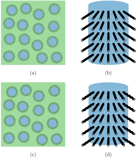
Figures 3a and 3c illustrate typical unidirectional fuzzy fiber composites,
in which the main fibers (made by carbon, glass or other material) are coated
with radially aligned straight (Figure 3b) or wavy (Figure 3d) carbon
nan-otubes (CNTs). The CNTs are represented as hollow microfibers. The fibers and the nanocomposite interphase (CNT+matrix) are arranged in such a way that they form a unidirectional lamina layer and are dispersed randomly inside the matrix.
The fibers (phase 1) and the matrix (phase 0) are assumed to be at most transversely isotropic with axis of symmetry parallel to the axis of the fibers. Thus, their elasticity tensors are expressed in the form
Li “ Lcyli “ » — — — — — — — — — — — — – Ktr i ` µtri Kitr´ µtri li 0 0 0 Ktr i ´ µtri Kitr` µtri li 0 0 0 li li ni 0 0 0 0 0 0 µtr i 0 0 0 0 0 0 µax i 0 0 0 0 0 0 µaxi fi ffi ffi ffi ffi ffi ffi ffi ffi ffi ffi ffi ffi fl , i“ 0, 1.
The material properties for these phases are the transverse bulk modulus1,
Ktr
i , the transverse shear modulus, µtri , the axial shear modulus, µaxi , and
the coefficients li and ni. These are considered known. It is noted that due
to their construction (at most transversely isotropic in the fiber direction), the above elasticity tensors remain unchanged during the transition from cylindrical to Cartesian coordinates.
1
(a) (b)
(c) (d)
Figure 3: (a) Unidirectional fuzzy fiber composite with straight carbon nanotubes. (b) Schematic of fuzzy fiber with straight carbon nanotubes. (c) Unidirectional fuzzy fiber composite with wavy carbon nanotubes. (d) Schematic of fuzzy fiber with wavy carbon nanotubes.
The fuzzy fiber composite can be considered as a three phase medium (Figure 2) consisting of the homogeneous fiber, the matrix and the heteroge-neous interphase (nanocomposite). The latter contains the CNTs and matrix material. The multiscale approach that is utilized for such medium consists
of two steps. The first homogenization step is performed on the nanocompos-ite and the new medium is treated as a homogenized coating layer attached to the main fibers. In the second step, the fibers, the coating and the matrix constitute the mesoscale. Homogenization at the mesoscale leads at obtain-ing the overall properties of the fuzzy fiber composite.
2.3. Microscale: CNTs embedded in matrix (nanocomposite)
matrix
CNT
matrix
CNT
(a) (b)
Figure 4: Microscale of the fuzzy fiber composite: (a) straight or (b) wavy carbon nan-otubes in matrix.
Figure 4 demonstrates a sketch of the microstructure of the
nanocom-posite. Its geometrical characteristics differ for straigt (Figure 4a) or wavy
(Figure 4b) CNTs. This subsection briefly discusses the method for obtaining
the effective properties of the nanotube reinforced interphase.
The diameter of the CNTs is at the order of nanotubes. Thus, the va-lidity of continuum mechanics concepts at such small scales is questionable. However, classical homogenization strategies for carbon nanotube reinforced composites are adopted frequently in the literature with quite satisfactory results (Seidel and Lagoudas, 2006).
The cylindrical structure of the nanocomposites’ RVE poses certain chal-lenges in terms of homogenization. To properly study such reinforced inter-phase via periodic homogenization, one has to consider that this composite presents cylindrical periodicity, in which the structure cannot be obtained by repetition of the same unit cell, as in Cartesian periodic composites. In addition, the volume fraction of the CNTs inside the matrix is reduced with the increase of the radial direction.
The most accurate technique for such microstructure is the asymptotic expansion homogenization, interpreted in cylindrical coordinates by Chatzi-georgiou et al. (2011) and for more complex microstructures the generalized periodicity homogenization (Tsalis et al., 2012; Guinovart-Sanjuán et al., 2016). The importance of cylindrical meso- and micro-coordinates is out-lined in the above papers, since they allow to consider a 2-D cell problem and represent in a consistent way the homogenization process for shell structures by exploiting the locally periodic homogenization techniques. The periodic microstructure depends on the radial distance, therefore the approximate locally periodic homogenization technique described in Tsalis et al. (2012) leads to a continuously graded effective material. This homogenization tech-nique is applied to several unit cells, whose effective properties are computed numerically.
Another important aspect in the behavior of a nanocomposite is the pos-sible agglomeration of carbon nanotubes. This phenomenon has been studied extensively in the literature of nanocomposites (Ma et al., 2008; Al-Saleh and Sundararaj, 2011). High volume fraction of CNTs that are not well dispersed can even cause decrease in the composite’s overall behavior (Bal and Samal,
2007). With regard to fuzzy fiber composites, high CNT content (over 40%) at the interphase between the fibers and the matrix has been reported in some studies (Chatzigeorgiou et al., 2012b; Ren et al., 2015; Zhou et al., 2016). To the best of the authors knowledge, the effects of CNTs agglomeration on the interphase regions of fuzzy fiber composites have not been investigated. In this manuscript, such aspects are not considered. However, one can account for agglomeration of CNTs through various micromechanics tecniques (Seidel and Lagoudas, 2006; Feng et al., 2007).
The results of the computational homogenization indicate that the effec-tive nanocomposite is cylindrically orthotropic with its coefficients spatially dependent on the mesoscale radial distance. In a rough but rather successful approximation, it is assumed that the nanocomposite behaves as a typical unidirectional fiber composite (see Seidel et al., 2014). This last assumption is also adopted in the present work. When the CNTs are wavy, the unidi-rectional microfiber composite properties can be identified through compu-tational (Kundalwal and Ray, 2014; Tsalis et al., 2017) or analytical (Yanase et al., 2013; Zhu et al., 2020) strategies.
In general, the microfibers are distributed on the fiber surface in a ran-dom way. For computational purposes, one can consider either tetragonal or hexagonal array packing of microfibers. The homogenized nanocomposite (phase 2) presents cylindrical orthotropy and its elasticity tensor is expressed
as Lcyl2 “ » — — — — — — — — — — — — – Lrr 2 Lrθ2 Lrz2 0 0 0 Lrθ 2 Lθθ2 Lθz2 0 0 0 Lrz 2 Lθz2 Lzz2 0 0 0 0 0 0 µrθ 2 0 0 0 0 0 0 µrz 2 0 0 0 0 0 0 µθz 2 fi ffi ffi ffi ffi ffi ffi ffi ffi ffi ffi ffi ffi fl .
The 9 material coefficients of this medium are Lrr
2 , Lθθ2 , Lzz2 , Lrθ2 , Lrz2 , Lθz2 ,
µrθ2 , µrz2 and µθz2 .
2.4. Mesoscale: fuzzy fiber embedded in matrix
(a)
”
NCP fiber matrix(b)
Figure 5: Mesoscale of the fuzzy fiber composite: (a) Hexagonal arrangement of fuzzy fibers. (b) Equivalent RVE where the CNTs and the surrounding matrix are substituted by a an interphase layer, the nanocomposite (NCP).
The random arrangement of the unidirectional fuzzy fibers in the matrix (Figure 3) can be approximated in the mesoscale RVE by a distribution in
a hexagonal array, as in Figure 5a (see the discussion in Hashin and Rosen,
their surrounding matrix are substituted by the equivalent nanocomposite
(Figure 5b). The latter mesoscale RVE can be treated numerically through
the periodic homogenization, but the computational cost is quite impor-tant due to the spatially dependent behavior, in Cartesian coordinates, of the nanocomposite. When dealing with the composite cylinders assemblage (CCA) approach, an equivalent RVE of concentric cylinders is introduced, as
in Figure 6a.
In Tsukrov et al. (2012); Chatzigeorgiou et al. (2012b), the CCA method has been used for evaluating the effective coefficients. By considering the mechanical response of the model to elementary load cases (axial tension, transverse hydrostatic tension, axial and transverse shear, thermal expan-sion) the effective thermomechanical behavior has been determined. Addi-tionally, to evaluate the effective transverse shear modulus, the generalized self consistent method has been applied, in which a composite cylinder is surrounded by a transversely isotropic infinite matrix, whose shear modulus is equal to the unknown modulus, subjected to remote shear strain.
In this contribution, the main novelty compared to the previous works on the fuzzy fiber composites modeling of Chatzigeorgiou et al. (2011, 2012a,b) and Kundalwal and Ray (2011, 2012, 2014) is the integration of the TFA framework into the homogenization scheme. The proposed methodology accounts for nonlinear mechanisms through the presence of inelastic stress fields. To the best of the authors knowledge, the transformation field anal-ysis has not been used in the literature before for the study of fuzzy fiber composites. The current approach permits to incorporate nonlinear mecha-nisms into the material constituents and to obtain appropriate concentration
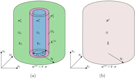
tensors, which provide the link between mesoscopic and macroscopic fields. Consider a coated cylindrical inhomogeneity, embedded in a matrix
mate-rial. The inhomogeneity is characterized by constant elasticity modulus L1,
occupies the space Ω1 with volume V1, bounded by the surface BΩ1 and
sub-jected to the uniform inelastic stress σ1p. The coating layer is characterized by
spatially varying elasticity modulus Lp2qpxq, occupies the space Ω
2 with
vol-ume V2, bounded by the surfaces BΩ1 andBΩ2 and subjected to the uniform
inelastic stress σ2p. It should be noted that, since the coating is cylindrically
orthotropic, Lp2q is spatially dependent in Cartesian coordinates. The
ma-trix is characterized by constant elasticity modulus L0, occupies the space Ω0
with volume V0, bounded by the surface BΩ0 and subjected to the uniform
inelastic stress σ0p. At the boundary of the coating, a linear displacement
field uext “ ε · x is applied (Figure 6
a), where ε denotes the macroscopic
strain tensor. As shown in Figures 6a and 6b, the space Ω “ Ω1 Y Ω2 Y Ω0
denotes the total RVE, whose volume is V “ V1` V2` V0.
For this RVE, the equilibrium equation reads
divσ “ 0, in Ω, (1) with σpxq “ $ ’ ’ ’ & ’ ’ ’ % L1:εpxq ` σ p 1, xP Ω1, Lp2qpxq: εpxq ` σ2p, xP Ω2, L0:εpxq ` σ p 0, xP Ω0. (2)
In the proposed analytical micromechanics scheme, an equivalent medium with unknown elasticity tensor L is considered to occupy the total space Ω, and is subjected: i) to the same displacement field at the boundary, and ii)
0 σp 0 σ p 1 σp 2 uext “ ε · x Ω0 Ω1 Ω2 L0 L1 L p2q 0 uext “ ε · x σp Ω L (a) (b)
Figure 6: (a) Coated cylindrical fiber, embedded in a matrix material. The fiber, the coating and the matrix have homothetic topology. The fiber and the matrix have constant elasticity moduli and uniform inelastic stresses, while the coating has spatially varying elastic modulus and uniform inelastic stress. Moreover, the system is subjected to linear macroscopic displacement. (b) Equivalent medium with equivalent uniform inelastic stress under the same boundary conditions.
to the uniform unknown inelastic stress σp (Figure 6
b). The main goal is to
identify the macroscopic constitutive law for this medium,
σ “ L: ε ` σp. (3)
The macroscopic stress and strain fields obey the standard relations with their microscopic counterparts
ε“ 2 ÿ i“0 ciεi, σ “ 2 ÿ i“0 ciσi, (4)
where the εi and σi denote average quantities per phase, εi “ 1 Vi ż Ωi εpxqdx, σi “ 1 Vi ż Ωi σpxqdx, (5)
for i=0,1,2 with ci denoting the volume fractions of the material constituents.
The applied macroscopic strain, ε, and the inelastic stresses, σ1p, σ
p 2, σ
p
0, are
known. The tasks of the analytical homogenization strategy are:
• To identify strain-type elastic, Ai, and inelastic, Apj,i, concentration
tensors that satisfy the relations
εi “ Ai:ε` 2 ÿ j“0 Apj,i:σp j, i“ 0, 1, 2. (6)
• To identify stress-type elastic, Di, and inelastic, Dj,ip , concentration
tensors that satisfy the relations
σi “ Di:ε`
2
ÿ
j“0
Dpj,i:σjp, i“ 0, 1, 2. (7)
Combining (3), (4)2 and (7) yields
L“ 2 ÿ i“0 ciDi, σp “ 2 ÿ j“0 Bjp:σp j, B p j “ 2 ÿ i“0 ciDpj,i. (8)
Bjp denote the inelastic stress concentration tensors. In the development of
the expressions (2)-(8) the crucial hypothesis is the uniformity of the inelas-tic fields inside the phases. Generally, the inelasinelas-tic stresses in the matrix and in the nanocomposite are expected to be strongly nonuniform.
How-ever, considering uniform inelastic stresses, σip, in all material phases is an
strategies. The inelastic stresses are considered to represent the average
in-elastic stresses in a phase2. The constitutive law (2) combined with the
expressions (6) “mimic” the classical TFA approach adopted in mean-field homogenization frameworks, like Mori-Tanaka. From a computational point of view, this hypothesis permits to easily account for nonlinear mechanisms like plasticity, viscoplasticity etc.. Indeed, an iterative multiscale computa-tional scheme for nonlinear materials uses the macroscopic strain field and expressions of the form (6) to identify the average strains per phase. The latter are utilized for predicting the inelastic stresses per phase.
The nonuniform spatial distribution of the inelastic fields inside the ma-trix phase is a known issue in the micromechanics community and usually leads to stiff macroscopic responses if classical approaches are followed. Cer-tain methodologies have been proposed in the literature to overcome these stiff predictions (see for instance Chaboche et al., 2005; Lahellec and Suquet, 2007; Brassart et al., 2012; Barral et al., 2020; Wu et al., 2017).
Inside the nanocomposite, the non-uniformity of inelastic fields is ex-pected to be strong due to its cylindrically orthotropic nature. In the present manuscript, the studied numerical examples examine the accuracy of the framework under known inelastic fields. In a forthcoming publication, the developed framework is going to be applied for composites with nonlinear fiber and coating phases, in which the inelastic fields are computed through appropriate incremental iterative schemes.
As a side note, thermal stresses are a special case of known inelastic fields
2
Thorough discussion about the implications arising from this assumption is given in Lagoudas et al. (1991).
which are incompatible with (2). To address this incompatibility, a special boundary value problem is studied in section 3.
3. Mesoscale RVE: effective properties and concentration tensors 3.1. Expressing the mesoscale problem in cylindrical coordinates
Inside the RVE of Figure 6a, the various mechanical fields generated at
every phase q (q “ 1, 2) depend on the spatial position, i.e.3
upqqpxq, εpqqpxq, σpqqpxq, σppqqpxq, @x P Ωq.
Due to the geometry of the inhomogeneities, the problem can be transformed in cylindrical coordinates, using a system of concentric cylinders for the fiber and the nanocomposite. In the cylindrical coordinate system, the strain tensor components at each phase are given by the expressions
εpqqrr “ Bu pqq r Br , ε pqq θθ “ 1 r Bupqqθ Bθ ` upqqr r , ε pqq zz “ Bupqqz Bz , 2εpqq rθ “ Bupqqθ Br ` 1 r Bupqqr Bθ ´ upqqθ r , 2ε pqq rz “ Bu pqq z Br ` Bupqqr Bz , 2εpqq θz “ 1 r Bupqqz Bθ ` Bupqqθ Bz , (9)
while the equilibrium equations per phase are written as Bσpqqrr Br ` 1 r Bσrθpqq Bθ ` σrrpqq´ σθθpqq r ` Bσrzpqq Bz “ 0, Bσrθpqq Br ` 1 r Bσθθpqq Bθ ` 2σpqq rθ r ` Bσθzpqq Bz “ 0, Bσpqqrz Br ` 1 r Bσθzpqq Bθ ` σrzpqq r ` Bσzzpqq Bz “ 0. (10) 3
In the sequel, the exponent pqq above a symbol will denote that the aforementioned
According to the RVE of Figure 6a, the fiber has radius r “ r1, the coating
layer has external radius r2 and the matrix has external radius r0. In the
sequel, the ratios
φc “ r2 1 r2 2 “ V1 V1` V2 , φm “ r2 2 r2 0 “ V1` V2 V , (11)
are introduced. Using these ratios, the volume fractions of the material
constituents, ci, are given by the expressions
c1 “ φcφm, c2 “ φmr1 ´ φcs, c0 “ 1 ´ φm. (12)
For the heterogeneous mesoscale RVE, the traction and displacement continu-ity between fiber-coating and between coating-matrix are expressed through the relations up1qk pr1, θ, zq “ u p2q k pr1, θ, zq, u p2q k pr2, θ, zq “ u p0q k pr2, θ, zq, k “ r, θ, z, σrkp1qpr1, θ, zq “ σ p2q rkpr1, θ, zq, σ p2q rkpr2, θ, zq “ σ p0q rkpr2, θ, zq, k “ r, θ, z.(13)
Concerning the analytical homogenization strategy, average fields per phase are required to be computed. Considering the phase q, which has inner
radius ra, outer radius rb and length 2L, its average strain and stress, in
Voigt notation, are given by the expressions
εq “ 1 2Lπrr2 b ´ r 2 as żL ´L ż2π 0 żrb ra q QT · εcylpqq rdrdθdz, σq “ 1 2Lπrr2 b ´ r 2 as żL ´L ż2π 0 żrb ra r QT · σcylpqq rdrdθdz. (14)
The rotation matrices qQand rQ are given in Appendix A.
is transversely isotropic with elasticity tensor expressed in the form L“ » — — — — — — — — — — — — – Ktr` µtr Ktr´ µtr l 0 0 0 Ktr´ µtr Ktr ` µtr l 0 0 0 l l n 0 0 0 0 0 0 µtr 0 0 0 0 0 0 µax 0 0 0 0 0 0 µax fi ffi ffi ffi ffi ffi ffi ffi ffi ffi ffi ffi ffi fl .
The unknown material properties are the transverse bulk modulus, Ktr, the
transverse shear modulus, µtr, the axial shear modulus, µax, and the
coeffi-cients l and n. The transverse isotropy of the overall medium has been verified in the past through the more accurate periodic homogenization framework (Chatzigeorgiou et al., 2011; Seidel et al., 2014). In the numerical example of the current article, the same conclusion is obtained.
Following the classical development of the Composite Cylinders Assem-blage approach, several boundary value problems are solved analytically. The adopted strategy has the following steps:
1. Apply special macroscopic boundary conditions and inelastic stresses per phase. The analytical solutions for these conditions are known up to several constants.
2. Obtain the values of constants by using the boundary and the interface conditions between layers.
3. Compute the various concentration tensors Ai, Apj,i, Di and Dj,ip for
4. Compute the macroscopic elasticity tensor, L, and the inelastic stress
concentration tensors, Bjp, using the expressions (8).
A small change in the above strategy is required for obtaining the macroscopic transverse shear modulus. In the relevant subsection, the details of this deviation are provided.
3.2. Axial shear 13 0 σp 0 σ p 1 σp 2 Ω0 Ω1 Ω2 L0 L1 L p2q 2ε13 2ε13
Figure 7: Axial shear conditions.
The applied displacement boundary conditions in the RVE are
uextz pr0, θ, zq “ 2βr0cosθ. (15)
This field corresponds to the macroscopic shear angle 2ε13 “ 2β (Figure 7).
The three phases are subjected to inelastic stresses whose non zero compo-nents per phase are
σppiq“ sicosθ, σ
ppiq
The latter corresponds to uniform shear stress on the plane x1 ´ x3. The
constants β, s1, s2 and s0 are known. The displacement fields at every r, θ
and z that satisfy the equilibrium equations (10) take the analytical forms
up1qr “ up1qθ “ 0, up1qz “ r Ξ1,1cosθ, up2qr “ up2qθ “ 0, up2qz “ r 2 ÿ i“1 Ξ2,i „ r r1 ξi´1 cosθ, up0qr “ up0qθ “ 0, up0qz “ r « Ξ0,1` Ξ0,2 „ r r2 ´2ff cosθ, (17) with ξ1 “ d µθz 2 µrz 2 , ξ2 “ ´ d µθz 2 µrz 2 . (18)
For the expression of up1qz , it has been taken into account that the
displace-ment at r “ 0 is finite. The values of the constants Ξi,j and the concentration
tensors terms Aixz, A
p
j,ixz, Dixz and D
p
j,ixz for i, j=0,1,2, are determined with
the procedure discussed in subsection B.1 of Appendix B.
Axial shear 23 conditions follow the same procedure: The applied dis-placement boundary conditions in the RVE are
uextz pr0, θ, zq “ 2βr0sinθ, (19)
which correspond to the macroscopic shear angle 2ε23“ 2β. The three phases
are subjected to inelastic stresses whose non zero components per phase are
σrzppiq “ sisinθ, σ
ppiq
θz “ sicosθ, i“ 0, 1, 2. (20)
The latter corresponds to uniform shear stress on the plane x2 ´ x3. The
θ and z that satisfy the equilibrium equations (10) take similar analytical forms with the ones of the axial shear 13 case, simply by exchanging cos θ with sin θ. Moreover, the obtained concentration tensor terms are exactly the same with those obtained in the axial shear 13 boundary value problem. 3.3. Transverse normal conditions
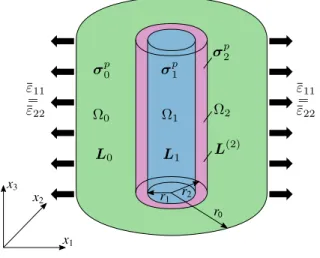
0 σp 0 σ p 1 σp 2 Ω0 Ω1 Ω2 L0 L1 L p2q ε11 ε11 ε“22 ε“22
Figure 8: Transverse normal conditions.
The applied displacement boundary conditions in the RVE are
uextr pr0, θ, zq “ βr0. (21)
This field corresponds to the biaxial macroscopic normal strain condition
ε11 “ ε22“ β (Figure 8). The three phases are subjected to inelastic stresses
whose non zero components per phase are
σrrppiq“ σθθppiq “ si, i“ 0, 1, 2. (22)
The latter corresponds to equibiaxial stress on the plane x1´ x2. The
z that satisfy the equilibrium equations (10) take the analytical forms up1qr “ r Ξ1,1, up1qθ “ up1qz “ 0, up2qr “ r 2 ÿ i“1 Ξ2,i „ r r1 ξi´1 , up2qθ “ up2qz “ 0, up0qr “ r « Ξ0,1` Ξ0,2 „ r r2 ´2ff , up0qθ “ up0qz “ 0, (23) with ξ1 “ d Lθθ 2 Lrr 2 , ξ2 “ ´ d Lθθ 2 Lrr 2 . (24)
For the expression of up1qr , it has been taken into account that the
displace-ment at r “ 0 is finite. The values of the constants Ξi,j and the concentration
tensors terms Aixx, A p j,ixx, Dixx, D p j,ixx, Dix{x and D p
j,ix{x for i, j=0,1,2, are
de-termined with the procedure discussed in subsection B.2 of Appendix B. 3.4. Axial conditions
The applied displacement boundary conditions in the RVE are
uextz pr, θ, ˘Lq “ ˘βL, uextr pr0, θ, zq “ 0. (25)
This field corresponds to the axial macroscopic normal strain ε33 “ β
(Fig-ure 9). The three phases are subjected to inelastic stresses whose non zero components per phase are
σzzppiq “ si, i“ 0, 1, 2. (26)
The latter corresponds to axial stress in the x3 direction. The constants β,
0 σp 0 σ p 1 σp 2 Ω0 Ω1 Ω2 L0 L1 L p2q ε33 ε33
Figure 9: Axial conditions.
the equilibrium equations (10) take the analytical forms
up1qr “ r Ξ1,1, u p1q θ “ 0, u p1q z “ βz, up2qr “ γ2βr` r 2 ÿ i“1 Ξ2,i „ r r1 ξi´1 , up2qθ “ 0, up2qz “ βz, up0qr “ r « Ξ0,1` Ξ0,2 „ r r2 ´2ff , up0qθ “ 0, up0qz “ βz, (27) with γ2 “ Lθz 2 ´ Lrz2 Lrr 2 ´ Lθθ2 , ξ1 “ d Lθθ 2 Lrr 2 , ξ2“ ´ d Lθθ 2 Lrr 2 . (28)
For the expression of up1qr , it has been taken into account that the
displace-ment at r “ 0 is finite. The values of the constants Ξi,j and the concentration
tensors terms Aix´z, Dix´z and Diz for i, j=0,1,2, are determined with the
σp 0 σ p 1 σp 2 Ω0 Ω1 Ω2 L0 L1 L p2q σp L rextÑ 8 r0 r1 r2 x1 x2 x3 σ12 σ12
Figure 10: Four cylinders RVE model used in the generalized self consistent approach and transverse shear conditions.
3.5. Transverse shear conditions
Following Christensen and Lo (1979), the Generalized Self Consistent Composite Cylinders Assemblage strategy is considered for this case. The traction boundary conditions are:
σext
rr prext, θ, zq “ β sin 2θ, σextrθ prext, θ, zq “ β cos 2θ, rext Ñ 8. (29)
These conditions correspond to macroscopic transverse shear stress σ12. A
fourth layer is added to the RVE, which is characterized by the unknown material properties L (Figure 10). The four phases are subjected to inelastic stresses whose non zero components per phase are
σppiqrr “ sisin 2θ, σ ppiq
θθ “ ´sisin 2θ, σ
ppiq
rθ “ sicos 2θ, i“ 0, 1, 2,
The latter correspond to transverse inelastic shear stresses on the plane
x1 ´ x2. s is the unknown macroscopic inelastic stress. The traction and
displacement continuity between the matrix and the equivalent medium are expressed through the relations
up0qk pr0, θ, zq “ u p3q k pr0, θ, zq, σ p0q rkpr0, θ, zq “ σ p3q rkpr0, θ, zq, k “ r, θ, z. (31)
The constants β, s1, s2 and s0 are known. The nonzero displacement fields at
every r, θ and z that satisfy the equilibrium equations (10) and the boundary conditions take the analytical forms
up1qr “ r « Z1Ξ1,1 „ r r1 2 ` Ξ1,2 ff sin 2θ, up1qθ “ r « Ξ1,1 „ r r1 2 ` Ξ1,2 ff cos 2θ, (32) up2qr “ r « 4 ÿ i“1 XiΞ2,i „ r r1 ξi´1ff sin 2θ, up2qθ “ r « 4 ÿ i“1 Ξ2,i „ r r1 ξi´1ff cos 2θ, (33) up0qr “ r « Z0Ξ0,1 „ r r2 2 ` Ξ0,2´ Ξ0,3 „ r r2 ´4 ` Z01Ξ0,4 „ r r2 ´2ff sin 2θ, up0qθ “ r « Ξ0,1 „ r r2 2 ` Ξ0,2` Ξ0,3 „ r r2 ´4 ` Ξ0,4 „ r r2 ´2ff cos 2θ, (34)
up3qr “ r 2µtr « β´ Ξ3 „ r r0 ´4 ` Z1Ξ4 „ r r0 ´2ff sin 2θ, up3qθ “ r 2µtr « β` Ξ3 „ r r0 ´4 ` Ξ4 „ r r0 ´2ff cos 2θ. (35)
In the above expressions,
Z1 “ Ktr 1 ´ µtr1 2Ktr 1 ` µtr1 , Z0 “ Ktr 0 ´ µtr0 2Ktr 0 ` µtr0 , Z01 “ Ktr 0 ` µtr0 µtr 0 , Z1 “ K tr ` µtr µtr , (36) and Xi “ 2 Lθθ 2 ´ ξiLrθ2 ` r1 ´ ξisµrθ2 Lθθ 2 ` 4µrθ2 ´ Lrr2 ξ 2 i , i“ 1, 2, 3, 4. (37)
Moreover, ξi are the four solutions of the following polynomial equation:
9Lθθ2 µrθ2 ` Lrr2 µrθ2 ξ4
i
`“4Lrθ2 rLrθ2 ` 2µrθ2 s ´ Lθθ2 µrθ2 ´ Lrr2 r4Lθθ2 ` µrθ2 s‰ξ2
i “ 0. (38)
The values of the constants Ξi,j and the concentration tensors terms Aixy,
Apj,ixy, Dixy and D
p
j,ixy for i, j=0,1,2, are determined with the procedure
dis-cussed in subsection B.4 of Appendix B. 3.6. Deviatoric conditions
This case is similar with the previous one. The applied traction boundary conditions are:
σextrr prext, θ, zq “ β cos 2θ,
σextθθ prext, θ, zq “ ´β cos 2θ,
Once again, a fourth layer is added to the RVE, which is characterized by the unknown material properties L. The four phases are subjected to inelastic stresses whose non zero components per phase are
σrrppiq “ sicosθ, σθθppiq “ ´sicos 2θ, σrθppiq “ ´sisin 2θ, i“ 0, 1, 2,
σrrpp3q“ s cos 2θ, σpp3qθθ “ ´s cos 2θ, σrθpp3q “ ´s sin 2θ, (40)
where s is the unknown macroscopic inelastic stress. The deviatoric con-ditions lead to similar solution with the transverse shear concon-ditions. The
displacement fields in all phases are expressed in the general form4
ur “ r « 4 ÿ i“1 XiΞi „ r r1 ξi´1ff cos 2θ, uθ “ ´r « 4 ÿ i“1 Ξi „ r r1 ξi´1ff sin 2θ. (41)
Some computational details for this boundary value problem are given in subsection B.5 of Appendix B.
3.7. Concentration tensors
The obtained concentration tensor terms from the previously discussed boundary value problems are sufficient to establish the complete form of the
4
tensors. Indeed, in Voigt notation they are written as Ai“ » — — — — — — — — — — — — — — — — — — – Aixx` Aixy 2 Aixx´ Aixy 2 Aix´z 0 0 0 Aixx´ Aixy 2 Aixx` Aixy 2 Aix´z 0 0 0 0 0 1 0 0 0 0 0 0 Ai xy 0 0 0 0 0 0 Ai xz 0 0 0 0 0 0 Ai xz fi ffi ffi ffi ffi ffi ffi ffi ffi ffi ffi ffi ffi ffi ffi ffi ffi ffi ffi fl , (42) Apj,i “ » — — — — — — — — — — — — — — — — — — – Apj,ixx` Apj,ixy{2 2 Apj,ixx´ Apj,ixy{2 2 0 0 0 0 Apj,ixx´ Apj,ixy{2 2 Apj,ixx` Apj,ixy{2 2 0 0 0 0 0 0 0 0 0 0 0 0 0 Ap j,ixy 0 0 0 0 0 0 Ap j,ixz 0 0 0 0 0 0 Ap j,ixz fi ffi ffi ffi ffi ffi ffi ffi ffi ffi ffi ffi ffi ffi ffi ffi ffi ffi ffi fl , (43) Di“ » — — — — — — — — — — — — — — — — — — – Dixx` 2Dixy 2 Dixx ´ 2Dixy 2 Dix´z 0 0 0 Dixx´ 2Dixy 2 Dixx ` 2Dixy 2 Dix´z 0 0 0 Dix{x 2 Dix{x 2 Diz 0 0 0 0 0 0 Di xy 0 0 0 0 0 0 Di xz 0 0 0 0 0 0 Di xz fi ffi ffi ffi ffi ffi ffi ffi ffi ffi ffi ffi ffi ffi ffi ffi ffi ffi ffi fl , (44)
and Dpj,i “ » — — — — — — — — — — — — — — — — — — — – Dpj,ixx` D p j,ixy 2 Dpj,ixx´ D p j,ixy 2 0 0 0 0 Dpj,ixx´ Dpj,ixy 2 Dpj,ixx` Dpj,ixy 2 0 0 0 0 Dpj,ix{x 2 Dj,ip x{x 2 δji 0 0 0 0 0 0 Dp j,ixy 0 0 0 0 0 0 Dp j,ixz 0 0 0 0 0 0 Dp j,ixz fi ffi ffi ffi ffi ffi ffi ffi ffi ffi ffi ffi ffi ffi ffi ffi ffi ffi ffi ffi fl , (45)
for i, j=0,1,2. All the constants of the above tensors are obtained through
the procedure described in the Appendix B. δji stands for the Kronecker
delta symbol, given in equation (B.1). 3.8. Thermal conditions
When a fuzzy fiber composite is subjected to thermal conditions, the nanocomposite experiences thermal stresses which are constant in the cylin-drical coordinate system. The thermal stress tensor is known, since it de-pends on material properties (elasticity and thermal conductivity tensors), and it takes the form
σ2th cyl “ ” sr 2 sθ2 sz2 0 0 0 ıT , where, in general, sr 2 ‰ sθ2 ‰ sz2. Transforming σ th cyl 2 to Cartesian
coordi-nates produces a spatially dependent σth
2 , which is incompatible with the
main hypothesis (2) for the constitutive law. To address this incompatibility for the thermal conditions, the following boundary value problem is studied
separately from the previously examined cases: The three phases of Figure
6a are subjected to inelastic stresses whose non zero components per phase
are σrrthp1q “ σθθthp1q “ str1, σ thp1q zz “ s ax 1 , σrrthp2q “ sr2, σ thp2q θθ “ s θ 2, σ thp2q zz “ s z 2, σrrthp0q “ σθθthp0q “ str0, σ thp0q zz “ s ax 0 . (46)
The displacement fields at every r, θ and z that satisfy the equilibrium equa-tions take the analytical forms
up1qr “ r Ξ1,1, u p1q θ “ u p1q z “ 0, up2qr “ rXrsr2´ sθ2s ` r 2 ÿ i“1 Ξ2,i „ r r1 ξi´1 , up2qθ “ up2qz “ 0, up0qr “ r « Ξ0,1` Ξ0,2 „ r r2 ´2ff , up0qθ “ up0qz “ 0, (47) with ξ1 “ d Lθθ2 Lrr 2 , ξ2 “ ´ d Lθθ2 Lrr 2 , X “ 1 Lθθ 2 ´ Lrr2 . (48)
For the expression of up1qr , it has been taken into account that the
displace-ment at r “ 0 is finite. The computational details for obtaining the
macro-scopic thermal stress tensor, σth, are provided in subsection B.6 of Appendix
B.
4. Numerical example
This section presents a numerical example of a fuzzy fiber composite with wavy carbon nanotubes. The scope is to investigate the accuracy of
the proposed methodology. In a forthcoming article, a proper parametric investigation and applications in nonlinear composites will demonstrate the method’s efficiency.
4.1. Material properties and geometrical characteristics
Concerning the material phases, the matrix is assumed to be a typical epoxy; the main fibers are made of glass and the carbon nanotubes walls are made of graphene. All these materials are isotropic and their properties are summarized in Table 1. While the graphene is considered isotropic, it should be noted that the effective behavior of a CNT, single-walled or multi-walled, is anisotropic. Straight CNTs behave as transversely isotropic effective media and their properties can be obtained through micromechanical techniques (Seidel and Lagoudas, 2006).
property epoxy glass graphene
Young’s Modulus [MPa] 3000 72000 1100000
Poisson’s ratio 0.3 0.2 0.14
Thermal expansion coefficient [1/K] 1.1E-4 5.0E-6 -3.75E-6
Table 1: Material properties of fuzzy fiber composite constituents. The mechanical proper-ties of graphene have been obtained from Chatzigeorgiou et al. (2012b), while the thermal from Shaina et al. (2016).
With regard to the microscale, the CNTs (hollow microfibers made of graphene) have internal radius 0.51 nm, external radius 0.85 nm (Chatzige-orgiou et al., 2012b). The wavy geometric characteristics of the CNT and its position inside the microscale RVE is illustrated in Figure 11. The width per
length ratio of the RVE is considered equal to 1/4, while the waviness of the CNT (height per length) is taken equal to 0.1. The CNTs are wavy in the
r´θ space, they appear in tetragonal arrangement inside the nanocomposite,
and their overall volume fraction in the nanocomposite is 10%.
With regard to the mesoscale, the glass fiber radius is taken equal to 2.5 µm, the length of the CNTs (i.e. thickness of nanocomposite) is equal to 2 µm, and the fuzzy fiber’s overall volume fraction in the composite is taken equal to 30%.
(a) (b)
Figure 11: (a) Wavy CNT and (b) RVE at the microscopic scale with tetragonal arrange-ment of CNTs.
4.2. Microscale homogenization: effective response of nanocomposite
The microscale RVE is solved with the help of the FE software ABAQUS. Periodicity conditions are imposed at the boundaries of the RVE and the mesoscopic strain is provided with the help of the constraint drivers concept (Praud, 2018; Tikarrouchine et al., 2018). Six linear perturbation analyses are performed to establish the complete elasticity tensor of the nanocompos-ite. For the thermal stresses, zero mesoscopic strain and unit temperature
are applied at the constraint drivers (Tikarrouchine et al., 2019). The FE computations have been performed using 150088 fully integrated ten-node tetrahedral elements (C3D10). The nanocomposite properties from this anal-ysis are summarized in Table 2. The effective thermal expansion coefficients
tensor, α2, can be computed by the classical relation
αcyl2 “ ´
” Lcyl2
ı´1
:σ2th cyl.
property value property value
Lrr 2 [MPa] 34420.2 µrθ2 [MPa] 1575.0 Lrθ 2 [MPa] 2568.0 µrz2 [MPa] 1416.2 Lrz 2 [MPa] 1940.5 µθz2 [MPa] 1349.4 Lθθ 2 [MPa] 4779.5 σ2th r [MPa/K] -0.6784 Lθz 2 [MPa] 1967.6 σ2th θ [MPa/K] -0.8161 Lzz 2 [MPa] 4712.8 σ2th z [MPa/K] -0.8193
Table 2: Thermomechanical properties of the nanocomposite obtained via periodic ho-mogenization.
4.3. Mesoscale homogenization: thermomechanical properties of fuzzy fiber composite
The mesoscale RVE is solved following two different approaches: (i) via periodic homogenization and (ii) via the CCA method proposed in the pre-vious section. The periodic homogenization, as a full-field approach, is con-sidered to be more accurate and thus it is used here as the reference solution.
Figure 12: Mesoscopic RVE of the fuzzy fiber composite according to the periodic homog-enization strategy. The fuzzy fibers appear with hexagonal arrangement.
L11 L56
(a) (b)
Figure 13: Spatial distribution of (a) L11 and (b) L56 component in the glass fiber and
the nanocomposite.
With respect to the periodic homogenization strategy, the nanocompos-ite properties obtained from the previous analysis are introduced in the RVE of Figure 12. This RVE consists of matrix and fuzzy fibers distributed in hexagonal arrangement. As Figure 13 shows, the cylindrically orthotropic nanocomposite is “translated” in the coordinate system of the mesoscale RVE
as a functionally graded monoclinic medium. Its material properties depend on the angular position. Due to this spatial dependency, the constitutive law of the nanocomposite is introduced in the FE software ABAQUS with the help of an appropriate user material (UMAT) subroutine. The performed analysis is 3-D, since though the composite is unidirectional, only one element
in the x3 direction is sufficient for accurate results. The FE computations
have been performed using 16552 fully integrated ten-node tetrahedral ele-ments (C3D10). The obtained results have been validated with performed analyses using two different meshes, one coarser (7391 C3D10 elements) and one finer (84787 C3D10 elements) than the chosen mesh in the present study. In the same spirit with the microscale analysis, periodicity conditions are imposed at the boundaries of the mesoscale RVE and the macroscopic strain is provided with the help of the constraint drivers concept. For the thermal stresses, zero macroscopic strain and unit temperature are applied at the constraint drivers.
Table 3 summarizes the results obtained from the periodic homogeniza-tion and from the CCA method as described in the previous sechomogeniza-tion. The relative error for each property is the absolute value of the difference between the results of the two methods, divided by the value given by the periodic homogenization. The first observation is that the periodic homogenization
results provide transversely isotropic response of the composite5. The
sec-ond observation is that the CCA method provides very accurate predictions. Its biggest deviation from the periodic homogenization results (0.8%) is
ob-5
Slight deviations in second and third digits are due to the numerical accuracy of the FE computations and inherent trancatures.
served in the transverse shear component, which has been obtained via the generalized self consistent composite cylinders methodology. This observa-tion was expected, since similar discrepancy between mean field and full field predictions has been frequently observed in the case of regular unidirectional fiber composites with moderate and high volume fraction of fibers (Hyer and Waas, 2000). The main reason for this discrepancy is that transverse shear loading leads to strain profiles inside the RVE that cannot be properly captured using the assumption of a single strain tensor per phase.
property PH CCA error
Ktr [MPa] 4185.5 4184.4 0.03% l [MPa] 2025.0 2024.8 0.01% n [MPa] 10630.5 10626.2 0.04% µtr [MPa] 1616.3 1629.7 0.83% µax [MPa] 1442.1 1441.9 0.01% σth tr [MPa/K] -0.8161 -0.8161 0.00% σth ax [MPa/K] -0.8097 -0.8097 0.00%
Table 3: Thermomechanical properties of the fuzzy fiber composite. Results obtained via periodic homogenization (PH) and CCA and relative error of CCA.
4.4. Mesoscale homogenization: fuzzy fiber composite response under macro-scopic strain and inelastic fields
To test the accuracy of the concentration tensors obtained from the an-alytical methodology of the previous section, an additional comparison be-tween the CCA and the periodic homogenization is provided below.
In the following example, the glass fiber and the nanocomposite are sub-jected to the uniform inelastic stresses
σ1p “ ´0.6 · ” 1 1 1 1 1 1 ıT MPa, σ2p “ ´0.4 · ” 1 1 1 1 1 1 ıT MPa.
The matrix is assumed to be free from inelastic stresses. In addition, the macroscopic strain ε“ 0.001 · ” 1 1 1 1 1 1 ıT , is applied in the mesoscale RVE.
The uniform inelastic stresses for both the glass fiber and the nanocom-posite are introduced in the FE periodic homogenization computations with the help of specially designed user material (UMAT) subroutines for the ABAQUS software. Moreover, the total macroscopic strain is applied at the constraint drivers. The distribution of the strains in the RVE from the periodic homogenization computations is illustrated in Figure 14.
The obtained macroscopic stresses, as well as the average strains and stresses per phase are summarized in Tables 4, 5 and 6, respectively. Again, it is observed an excellent agreement between the CCA and the periodic ho-mogenization. The maximum deviation in the macroscopic and the average fields between the finite element simulations and the analytical model com-putations is observed in the transverse components. This phenomenon is due to the same reasons that cause deviation in the transverse shear modulus pre-dictions, i.e. the difficulty of the mean field techniques to capture properly
(a) (b)
(c)
Figure 14: Distribution of strains in the mesoscale RVE: (a) 11 normal strain, (b) 12 shear angle and (c) 13 shear angle.
the strain profiles in the RVE under transverse shearing at moderate and high fiber volume fractions.
σ11 σ22 σ33 σ44 σ55 σ66
PH 10.3629 10.3631 14.5687 1.5660 1.3553 1.3554
CCA 10.3605 10.3605 14.5640 1.5785 1.3552 1.3552
error 0.02% 0.02% 0.03% 0.80% 0.01% 0.01%
Table 4: Macroscopic inelastic stresses obtained via periodic homogenization (PH) and CCA and relative error of CCA. The stress components units are in MPa.
ε11 ε22 ε33 ε44 ε55 ε66
fi
b
er
PH 1.92E-6 1.94E-6 1.00E-3 1.13E-4 1.06E-4 1.06E-4
CCA 1.89E-6 1.89E-6 1.00E-3 1.16E-4 1.06E-4 1.06E-4
error 1.74% 2.44% 0.00% 2.41% 0.01% 0.01%
N
C
P
PH 2.50E-4 2.51E-4 1.00E-3 6.29E-4 1.10E-3 1.10E-3
CCA 2.50E-4 2.50E-4 1.00E-3 6.37E-4 1.10E-3 1.10E-3
error 0.01% 0.04% 0.00% 1.26% 0.00% 0.01%
m
at
ri
x PH 1.35E-3 1.35E-3 1.00E-3 1.23E-3 1.09E-3 1.09E-3
CCA 1.35E-3 1.35E-3 1.00E-3 1.22E-3 1.09E-3 1.09E-3
error 0.02% 0.02% 0.00% 0.24% 0.01% 0.01%
Table 5: Average strains in the fiber, the nanocomposite (NCP) and the matrix. Results are obtained via periodic homogenization (PH) and CCA.
5. Conclusions
This manuscript has presented a micromechanical framework for identify-ing the overall response of a fuzzy fiber composite. The main novelties of the developed approach are: i) it is applicable for fibers coated with straight or wavy carbon nanotubes, and ii) it accounts for inelastic mechanical and ther-mal fields. The proposed method for the mesoscale problem of the composite computes strain-type and stress-type concentration tensors through the CCA approach. The inelastic fields are taken into account via the TFA strategy. A numerical example of a fuzzy fiber composite with wavy nanotubes and com-parisons with full field (periodic homogenization) computations illustrates
σ11 σ22 σ33 σ44 σ55 σ66 fi b er PH 19.5924 19.5932 79.4771 2.7939 2.5880 2.5881 CCA 19.5888 19.5888 79.4755 2.8756 2.5878 2.5878 error 0.02% 0.02% 0.00% 2.92% 0.01% 0.01% N C P PH 9.0002 9.0010 5.2883 1.5229 1.1448 1.1449 CCA 8.9987 8.9987 5.2880 1.5587 1.1447 1.1447 error 0.02% 0.02% 0.01% 2.35% 0.00% 0.01% m at ri x PH 9.5451 9.5451 8.7272 1.4162 1.2546 1.2546 CCA 9.5434 9.5434 8.7262 1.4128 1.2545 1.2545 error 0.02% 0.02% 0.01% 0.24% 0.01% 0.01%
Table 6: Average stresses in the fiber, the nanocomposite (NCP) and the matrix. Results are obtained via periodic homogenization (PH) and CCA. The stress components units are in MPa.
the excellent accuracy of the micromechanical founded approach.
The developed strategy has considered one set of properties to describe the overall behavior of the nanocomposite layer. In the presence of wavy CNTs, this nanocomposite behaves as a cylindrically orthotropic medium. The proposed methodology can be easily extended to express the response of the nanocomposite with more than one layers, as it is the case for the approximate locally periodic homogenization strategy. This extension could allow to combine, in the future, the CCA approach with other methods at the microscopic scale (Tsalis et al., 2012).
The present manuscript focuses on establishing a new micromechanical framework for fuzzy fiber composites. The numerical example has been uti-lized to validate the appoach. In a forthcoming paper, a proper parametric investigation with several fuzzy fiber configurations and specific applications in non-linear composites will demonstrate the capabilities and potential ap-plications of the proposed method.
References
Al-Saleh, M. H., Sundararaj, U., 2011. Review of the mechanical properties of carbon nanofiber/polymer composites. Composites: Part A 42, 2126–2142. Avery, W. B., Herakovich, C. T., 1986. Effect of fiber anisotropy on thermal stresses in fibrous composites. Journal of Applied Mechanics 53, 751–756. Bal, S., Samal, S. S., 2007. Carbon nanotube reinforced polymer composites
- A state of art. Bulletin of Materials Science 30 (4), 379–386.
Barral, M., Chatzigeorgiou, G., Meraghni, F., Léon, R., 2020. Homogeniza-tion using modified Mori-Tanaka and TFA framework for elastoplastic-viscoelastic-viscoplastic composites: Theory and numerical validation. In-ternational Journal of Plasticity 127, 102632.
Batra, R. C., Sears, A., 2007. Uniform radial expansion/contraction of carbon nanotubes and their transverse elastic moduli. Modelling and Simulation in Materials Science and Engineering 15, 835–844.
of elasto-(visco) plastic composites based on an incremental variational principle. International Journal of Plasticity 36, 86–112.
Chaboche, J., Kanoute, P., Ross, A., 2005. On the capabilities of mean field approaches for the description of plasticity in metal matrix composites. International Journal of Plasticity 21, 1409–1434.
Chatzigeorgiou, G., Charalambakis, N., Chemisky, Y., Meraghni, F., 2018. Thermomechanical Behavior of Dissipative Composite Materials. ISTE Press - Elsevier, London.
Chatzigeorgiou, G., Efendiev, Y., Charalambakis, N., Lagoudas, D. C., 2012a. Effective Thermoelastic Properties of Composites with Periodicity in Cylindrical Coordinates. International Journal of Solids and Structures 49 (18), 2590–2603.
Chatzigeorgiou, G., Efendiev, Y., Lagoudas, D. C., 2011. Homogenization of aligned ”fuzzy fiber” composites. International Journal of Solids and Structures 48 (19), 2668–2680.
Chatzigeorgiou, G., Meraghni, F., 2019. Elastic and inelastic local strain fields in composites with coated fibers or particles: Theory and validation. Mathematics and Mechanics of Solids 24 (9), 2858–2894.
Chatzigeorgiou, G., Seidel, G. D., Lagoudas, D. C., 2012b. Effective mechan-ical properties of aligned ”fuzzy fiber” composites. Composites Part B: Engineering, special issue ”Homogenization and Micromechanics of Smart and Multifunctional Materials” 43, 2577–2593.
Chen, T., Dvorak, G. J., Benveniste, Y., 1990. Stress fields in composites re-inforced by coated cylindrically orthotropic fibers. Mechanics of Materials 9, 17–32.
Christensen, R. M., 1979. Mechanics of composite materials. Dover, New York.
Christensen, R. M., Lo, K. H., 1979. Solutions for effective shear properties in three phase sphere and cylinder models. Journal of the Mechanics and Physics of Solids 27, 315–330.
Dhala, S., Ray, M. C., 2015. Micromechanics of piezoelectric fuzzy fiber-reinforced composite. Mechanics of Materials 81, 1–17.
Dvorak, G., 1992. Transformation field analysis of inelastic composite mate-rials. Proceedings of the Royal Society of London A 437, 311–327.
Dvorak, G., Benveniste, Y., 1992. On transformation strains and uniform fields in multiphase elastic media. Proceedings of the Royal Society of London A 437, 291–310.
Feng, X. Q., Shi, D. L., Huang, Y. G., Hwang, K. C., 2007. Micromechanics and multiscale mechanics of carbon nanotubes-reinforced composites. In: Sih, G. C. (Ed.), Multiscaling in Molecular and Continuum Mechanics: Interaction of Time and Size from Macro to Nano: Application to biology, physics, material science, mechanics, structural and processing engineer-ing. Springer Netherlands, Dordrecht, pp. 103–139.
Guinovart-Sanjuán, D., Rodríguez-Ramos, R., Guinovart-Díaz, R., Bravo-Castillero, J., Sabina, F. J., Merodio, J., Lebon, F., Dumont, S., Conci,
A., 2016. Effective properties of regular elastic laminated shell composite. Composites Part B 87, 12–20.
Hart, H. C., Koizumi, R., Hamel, J., Owuor, P. S., Ito, Y., Ozden, S., Bhowmick, S., Amanulla, S. A. S., Tsafack, T., Keyshar, K., Mital, R., Hurst, J., Vajtai, R., Tiwary, C. S., Ajayan, P. M., 2017. Velcro-Inspired SiC Fuzzy Fibers for Aerospace Applications. ACS Applied Materials & Interfaces 9 (15), 13742–13750.
Hashin, Z., 1990. Thermoelastic properties of fiber composites with imperfect interface. Mechanics of Materials 8, 333–348.
Hashin, Z., Rosen, B. W., 1964. The elastic moduli of fiber-reinforced mate-rials. Journal of Applied Mechanics 31, 223–232.
Honjo, K., 2007. Thermal stresses and effective properties calculated for fiber composites using actual cylindrically-anisotropic properties of interfacial carbon coating. Carbon 45, 865–872.
Hyer, M. W., Waas, A. M., 2000. Micromechanics of Linear Elastic Contin-uous Fiber Composites. In: Kelly, A., Zweben, C. (Eds.), Comprehensive Composite Materials. Vol. 1. Pergamon, Oxford, pp. 345–375.
Kundalwal, S. I., Meguid, S. A., 2015. Micromechanics modelling of the effec-tive thermoelastic response of nano-tailored composites. European Journal of Mechanics A/Solids 53, 241–253.
Kundalwal, S. I., Ray, M. C., 2011. Micromechanical analysis of fuzzy fiber reinforced composites. International Journal of Mechanics and Materials in Design 7, 149–166.
Kundalwal, S. I., Ray, M. C., 2012. Effective properties of a novel continuous fuzzy-fiber reinforced composite using the method of cells and the finite element method. European Journal of Mechanics - A/Solids 36, 191–203. Kundalwal, S. I., Ray, M. C., 2014. Effect of carbon nanotube waviness
on the effective thermoelastic properties of a novel continuous fuzzy fiber reinforced composite. Composites Part B: Engineering 57, 199–209. Lagoudas, D. C., Gavazzi, A. C., Nigam, H., 1991. Elastoplastic behavior of
metal matrix composittes based on incremental plasticity and the Mori-Tanaka averaging scheme. Computational Mechanics 8, 193–203.
Lahellec, N., Suquet, P., 2007. On the effective behavior of nonlinear inelastic composites: I. Incremental variational principles. Journal of the Mechanics and Physics of Solids 55 (9), 1932–1963.
Ma, A. W. K., Yearsley, K. M., Chinesta, F., Mackley, M. R., 2008. A review of the microstructure and rheology of carbon nanotube suspensions. Proceedings of the Institution of Mechanical Engineers, Part N: Journal of Nanoengineering and Nanosystems 222 (3), 71–94.
Michel, J. C., Suquet, P., 2003. Nonuniform transformation field analysis. International Journal of Solids and Structures 40, 6937–6955.
Praud, F., 2018. Multi-scale modelling of thermoplastic-based woven compos-ites, cyclic and time-dependent behaviour. Ph.D. thesis, Arts et Métiers ParisTech, Metz.
Ren, X., Burton, J., Seidel, G. D., Lafdi, K., 2015. Computational multiscale modeling and characterization of piezoresistivity in fuzzy fiber reinforced
polymer composites. International Journal of Solids and Structures 54, 121–134.
Sager, R. J., Klein, P. J., Lagoudas, D. C., Zhang, Q., Liu, J., Dai, L., Baur, J. W., 2009. Effect of carbon nanotubes on the interfacial shear strength of T650 carbon fiber in an epoxy matrix. Composites Science and Technology 69, 898–904.
Sebastian, J., Schehl, N., Bouchard, M., Boehle, M., Li, L., Lagounov, A., Lafdi, K., 2014. Health monitoring of structural composites with embedded carbon nanotube coated glass fiber sensors. Carbon 66, 191–200.
Seidel, G. D., Chatzigeorgiou, G., Ren, X., Lagoudas, D. C., 2014. Multiscale Modeling of Multifunctional Fuzzy Fibers based on Multi-Walled Carbon Nanotubes. In: Tserpes, K. I., Silvestre, N. P. (Eds.), Modeling of Carbon Nanotubes, Graphene and their Composites. Vol. 188 of Springer Series in Materials Science. Springer International Publishing, Cham, pp. 135–176. Seidel, G. D., Lagoudas, D. C., 2006. Micromechanical analysis of the effec-tive elastic properties of carbon nanotube reinforced composites. Mechanics of Materials 38, 884–907.
Shaina, P. R., George, L., Yadav, V., Jaiswal, M., 2016. Estimating the thermal expansion coefficient of graphene: the role of graphene-substrate interactions. Journal of Physics: Condensed Matter 28, 085301.
Shen, L., Li, J., 2004. Tranversely isotropic elastic properties of single-walled carbon nanotubes. Physical Review B 69, 345–414.
Tikarrouchine, E., Chatzigeorgiou, G., Chemisky, Y., Meraghni, F., 2019. Fully coupled thermo-viscoplastic analysis of composite structures by means of multi-scale three-dimensional finite element computations. In-ternational Journal of Solids and Structures 164, 120–140.
Tikarrouchine, E., Praud, F., Chatzigeorgiou, G., Piotrowski, B., Chemisky,
Y., Meraghni, F., 2018. Three-dimensional FE2
method for the simulation of non-linear, rate-dependent response of composite structures. Composite Structures 193, 165–179.
Tsalis, D., Charalambakis, N., Bonnay, K., Chatzigeorgiou, G., 2017. Effec-tive properties of multiphase composites made of elastic materials with hierarchical structure. Mathematics and Mechanics of Solids 22 (4), 751– 770.
Tsalis, D., Chatzigeorgiou, G., Charalambakis, N., 2012. Homogenization of structures with generalized periodicity. Composites Part B: Engineering, special issue ”Homogenization and Micromechanics of Smart and Multi-functional Materials” 43, 2495–2512.
Tsukrov, I., Drach, B., 2010. Elastic deformation of composite cylinders with cylindrically orthotropic layers. International Journal of Solids and Struc-tures 47, 25–33.
Tsukrov, I., Drach, B., Gross, T. S., 2012. Effective stiffness and thermal ex-pansion coefficients of unidirectional composites with fibers surrounded by cylindrical orthotropic matrix layers. International Journal of Engineering Science 58, 129–143.
Wu, L., Adam, L., Doghri, I., Noels, L., 2017. An incremental-secant mean-field homogenization method with second statistical moments for elasto-visco-plastic composite materials. Mechanics of Materials 114, 180–200. Xiao, J. R., Gama, B. A., Gillespie, J. W., 2005. An analytical molecular
structural mechanics model for the mechanical properties of carbon nan-otubes. International Journal of Solids and Structures 42, 3075–3092. Yanase, K., Moriyama, S., Ju, J. W., 2013. Effects of CNT waviness on
the effective elastic responses of CNT-reinforced polymer composites. Acta Mechanica 224, 1351–1364.
Zhou, H. W., Mishnaevsky Jr, L., Yi, H. Y., Liu, Y. Q., Hu, X., Warrier, A., Dai, G. M., 2016. Carbon fiber/carbon nanotube reinforced hierarchical composites: Effect of CNT distribution on shearing strength. Composites Part B 28, 085301.
Zhu, F., Park, C., Yun, G. J., 2020. An extended Mori-Tanaka micromechan-ics model for wavy CNT nanocomposites with interface damage. Mechanmicromechan-ics of Advanced Materials and Structures, in press.
A. Transformation between coordinate systems
In Voigt notation, strains and stresses are represented as 6ˆ 1 vectors.
The displacement, strain and stress fields are transformed between cylindrical and Cartesian coordinate systems through the matrix-type formulas
ucyl “ RT · u, εcyl “ rQ· ε, σcyl “ qQ· σ,
u“ R · ucyl, ε“ qQT· εcyl, σ
where R is the rotator second order tensor R“ » — — — – cosθ ´ sin θ 0 sinθ cosθ 0 0 0 1 fi ffi ffi ffi fl.
and rQ, qQare proper fourth order rotators that transform second order
ten-sors in Voigt notation (Chatzigeorgiou et al., 2018),
r Q“ » — — — — — — — — — — — — – cos2
θ sin2θ 0 cosθ sin θ 0 0
sin2θ cos2θ 0 ´ cos θ sin θ 0 0
0 0 1 0 0 0
´2 cos θ sin θ 2 cos θ sin θ 0 cos2
θ´ sin2 θ 0 0 0 0 0 0 cosθ sinθ 0 0 0 0 ´ sin θ cos θ fi ffi ffi ffi ffi ffi ffi ffi ffi ffi ffi ffi ffi fl , q Q“ » — — — — — — — — — — — — – cos2 θ sin2 θ 0 2 cosθ sin θ 0 0 sin2θ cos2 θ 0 ´2 cos θ sin θ 0 0 0 0 1 0 0 0
´ cos θ sin θ cos θ sin θ 0 cos2
θ´ sin2θ 0 0 0 0 0 0 cosθ sinθ 0 0 0 0 ´ sin θ cos θ fi ffi ffi ffi ffi ffi ffi ffi ffi ffi ffi ffi ffi fl .
With the help of the above rotators, the transformation of a stiffness tensor
L takes the form