Science Arts & Métiers (SAM)
is an open access repository that collects the work of Arts et Métiers Institute of
Technology researchers and makes it freely available over the web where possible.
This is an author-deposited version published in:
https://sam.ensam.eu
Handle ID: .
http://hdl.handle.net/10985/13838
To cite this version :
Richard A. BUSWELL, Wilson R. LEAL DE SILVA, S.Z. JONES, Justin DIRRENBERGER - 3D
printing using concrete extrusion: A roadmap for research - Cement and Concrete Research - Vol.
112, p.37-49 - 2018
Any correspondence concerning this service should be sent to the repository
Administrator :
[email protected]
3D printing using concrete extrusion: A roadmap for research
R.A. Buswell
a,*, W.R. Leal de Silva
b, S.Z. Jones
c, J. Dirrenberger
d,e aSchool of Architecture, Building and Civil Engineering, Loughborough University, UKbThe Concrete Centre, The Danish Technological Institute, Denmark cEngineering Laboratory, National Institute of Standards and Technology, USA dLaboratoire PIMM, Arts et Métiers-ParisTech, Cnam, CNRS, Paris, France eXtreeE, 18/20 rue du Jura, CP 40502, Rungis Cedex 94623, France
A R T I C L E I N F O Keywords: Concrete printing Extrusion 3DCP Rheology Hardened properties Measurement Geometric conformity A B S T R A C T
Large-scale additive manufacturing processes for construction utilise computer-controlled placement of extruded cement-based mortar to create physical objects layer-by-layer. Demonstrated applications include component manufacture and placement of in-situ walls for buildings. These applications vary the constraints on design parameters and present different technical issues for the production process. In this paper, published and new work are utilised to explore the relationship between fresh and hardened paste, mortar, and concrete material properties and how they influence the geometry of the created object. Findings are classified by construction application to create a matrix of issues that identifies the spectrum of future research exploration in this emergingfield.
1. Introduction
Large-scale, cement-based additive manufacturing processes, often referred to as 3D concrete printing (3DCP), have been under develop-ment for the last 10 years and more than 30 groups world-wide are currently engaged in research. 3DCP disposes of the need for conven-tional moulds by precisely placing, or solidifying, specific volumes of material in sequential layers by a computer controlled positioning process. The manufactured component is a facsimile of a 3D model from which the machine control is derived in the same way as conventional Additive Manufacturing/Rapid Prototyping: see either[1]or[2]for an overview of these processes and their operation. Fig. 1describes the growth in activity since the seminal work of Pegna[3], a recent con-temporary review of the literature is offered in[4].
A distinction is made here between automation methods for mould making and material shaping [5,6] and methods that ‘build’ using discrete layer deposition. A further distinction is made between the discrete layer deposition processes that are based on a particle bed approach [3,7] (and Lowke et al.[8]in this issue) and those based on extrusion.
Over half the processes under development employ extrusion, ty-pically a small (∼6 mm to ∼50 mm diameter) continuous filament, pumped through a nozzle often mounted on a gantry or robotic arm that positions the material during the build process. The material is typically a high cement content mortar, with a maximum particle size
in the order of 2 mm to 3 mm, although larger aggregates have been used. The shape of the extrusion varies and is either circular, ovular or rectangular and linear rates of extrusion are in the range of 50 mm/s to 500 mm/s.Fig. 2 offers examples of the component types, print or-ientations and geometrical features that have been demonstrated and can be classified into the three application families:
•
components, either stand alone (c) or for assembly (d and e);•
walls and columns printed in-situ (f); and,•
permanent shuttering where the shutter is printed and the structural element is cast conventionally (a and b).The orientation of manufacture also varies and is either pre-dominantly vertical (Fig. 2b, c, d and f) or horizontal (Fig. 2a and e). Components can be predominately planar (Fig. 2a, b, d, e and f) or volumetric (Fig. 2c). The creation of overhanging features may also be desirable and can be produced through corbeling (Fig. 2d) or by the additional application of a removable material to create support during printing, as has been used to createFig. 2e. Voids can also be created to form shafts in vertical prints, such as those to the left hand end of the bench inFig. 2c.
Research to date has been ad-hoc, focused on demonstrating via-bility [1,9-11]. Currently 3DCP manufacturing processes are incon-sistent and unreliable, requiring expert machine operators and extra-ordinary care in the preparation and formulation of materials.
Corresponding author.
E-mail address:[email protected](R.A. Buswell).
Inconsistencies and unreliability arise from the dependency of material properties on the process apparatus, the operational parameters, and the generation of machine instructions from an algorithm to create the desired geometry. The material is required toflow and extrude through a nozzle, bond with the previous layer and maintain its shape under increasing hydrostatic pressure generated by subsequent layer deposi-tion. Disturbances during printing, caused by changes in the material or problems with the process, are detrimental to the success of a build and can influence the performance of the component.
These issues hamper the robustness of 3CDP, a critical milestone for commercial viability, of which rheological properties of 3DCP materials are fundamentally important. It is, however, the hardened properties and conformity to design geometry that give the manufactured com-ponent value. Indeed, if these processes are to become common
construction practice, engineers will need to understand how to design structures to be manufactured with printed materials, leading to new design codes and standardised methods of testing.
2. Method and approach
This paper provides a structured insight into the technical issues and solutions surrounding 3DCP and discusses:
•
properties of wet materials used in 3DCP prior to solidification;•
hardened properties of 3DCP materials;•
achieving geometric conformity; and,•
factors affected by application.A thorough literature review in the area of 3DCP resulted in 50 to 60 topically relevant papers that werefiltered by removing review papers and work that did not focus on mortar extrusion-based 3DCP. The re-maining papers were then reviewed to establish whether they com-mented on or provided evidence of technical issues. Observations were either based on structured investigation or experience and both were included to form an evidence base of about 22 papers.
Reflecting on the key challenges outlined by Wangler et al.[12], the issues highlighted by these publications are supplemented with new insights from recent international work undertaken at Loughborough University (UK), The Danish Technological Institute, the National In-stitute of Standards and Technology (USA) and Conservatoire National des Arts et Métiers (France). Reflective discussion is provided throughout, touching on issues relating to the measurement and testing of rheology and hardened material properties.
The work aims to provide a state-of-the-art review that can be readily evidenced and related to key areas of material research, sign-posting the latest publications in this special issue. At the same time, it identifies the interdependent factors effecting, and effected by, the component design and the mechanics and control of the process. These issues and their interrelationships, are then collated to create a matrix
Fig. 1. The rise in large-scale additive manufacturing for construction appli-cations since the concept inception in 1997.
a) a panel, horizontally printed, shell and fill application. Image: 4TU project 3D printing on flexible mould TU Delft and TU Eindhoven, Netherlands.
b) an in-situ wall, vertically printed, shell and fill application. Image credit: Winsun, China
Source: https://3dprint.com/38144/3d-printed-apartment-building/
c) a solid geometry, vertically printed component. Image: Loughborough University, UK.
d) a vertically printed panel component. Image: courtesy of XTreeE, France
e) horizontal component manufacture. Image: Loughborough University, UK
f) vertically printed, in-situ walls and columns. Image: courtesy of Andrey Rudenko, Total Kustom, USA
of research and development issues that are dependent on the manu-facturing application. This matrix is offered to bring insight and structure to help frame and direct future research and the developing discourse around the technology. The paper concludes with a vision statement describing the anticipated features and capabilities of design through manufacture using 3DCP processes in order to inspire creative thinking around the research issues.
3. Issues part I: fresh state
3DCP mix design has its foundation in wet mixed mortars used in spraying applications: it must be both pumped and sustain its shape with little or no deformation after extrusion. The qualitative descriptors pumpability, extrudability, and buildability, as they relate to 3DCP were introduced by Le et al.[13]and this section attempts to relate these to the rheological and physical properties of mortars by focusing on:
•
open time, time during which a material may be used in 3DCP, and its influence on pumping and extrusion;•
setting and layer cycle-time, time required to complete one build layer, and its influence on vertical build rate;•
deformation of material as successive layers are added; and,•
rheology measurements and its importance to quality control. 3.1. Open time, pumping and extrusionPumpability describes the ease with which the fresh mix is trans-ported from the pump to the extrusion nozzle [13]. One problem is particle segregation in the hose which can lead to blockages caused by mix design and/or insufficient mixing prior to pumping. 3DCP is par-ticularly sensitive to pauses in the build process because components are created through the sequential layering of materials which must bond to form a homogeneous component, thus there is greater potential to form cold joints between layers than in more conventional casting methods[14].
Positive displacement pumps are frequently utilised for 3DCP and suitable mortars include sufficient paste content to form a lubricating layer on the inside of the delivery pipe. Le et al.[13]found the yield stress zone that prevents blockage during pumping and subsequent extrusion without filament fracture, to be in the range 0.3 kPa to 0.9 kPa. An independent investigation using a 4C-Mini Rheometer
Thrane et al.[15]at the Danish Technological Institute was in agree-ment with thesefindings, demonstrating that mixtures with a plastic viscosity and yield stress equal to (38.7 ± 4.5) Pa.s and (0.59 ± 0.08) kPa respectively (for mixes with CEM I and Fly Ash) and (21.1 ± 2.4) Pa.s and (0.27 ± 0.03) kPa respectively (for mixes with CEM I and Limestonefiller) were suitable for pumping and extrusion. Thesefigures offer guidance values for mix design and process devel-opment.
In conventional concrete, the term open time is associated with concrete slump loss, which is related to the onset of the acceleration period during hydration. Similarly in 3DCP, open time is associated with the maintenance of the viscosity and yields stress of the mix which is critical to the process. Open time has been related to an‘operation window’ where a specified volume of material must be extruded [12,16]. This is complicated by the volume of the printed component and area of the working surface of the build, which determines the total length of the deposited material per layer. Given a rate of deposition, this amounts to afinite time to deposit each layer, called the ‘cycle-time’, discussed further inSection 3.2. This determines the time delay between fresh mortar being placed in the same location on top of the previous layer.
There is some debate about whether conventional batching is the most suitable method, whether micro-batching is more appropriate, and whe-ther instantaneous mixing at the deposition head could be developed to alleviate these issues. The size of the batch is dependent on the process volume deposition rate and the component geometry, which affects the size and type of mixer used. It is not trivial to separate these factors, al-though the development and application of admixtures to help stabilise the mix and extend open time is one area of research that requires at-tention (discussed by Reiter et al.[17]in this issue). The ability to simulate and model the whole 3DCP process from batching to production to curing will also become a critical component of successful manufacturing.
The shape of extrusion nozzles varies but the majority are either round[16], or rectangular [18,19].‘Extrudability ’ is defined here as the ability to extrude the mix through a nozzle without considerable cross-sectional deformation and with an acceptable degree of splitting/ tearing offilament:Fig. 3provides examples. There are no formal re-ference tests to evaluate the extrudability and currently this is eval-uated by visual inspection. This definition is slightly different to that proposed in[13]and is effected by the shape and size of the extrusion nozzle and the nozzle movement and position in relation to the previous layer.
Fig. 3. Extrusion with a 40 mm × 10 mm rectangular nozzle: a) good quality concretefilament without signs of tearing, b) concrete filament with signs of tearing during extrusion caused by the lack of paste volume, and c) concretefilament splitting observed in layers 12 and 13 and filament tearing from layers 1 to 16.
3.2. Layer cycle-time
Printing a component requires the extrusion to follow afinite path that positions the deposited material which often is repeated at every layer to build vertical height. The length of the extrusion path and the speed with which material can be placed are key factors that effect both the pro-duction time of the component and the time taken to overlay layers, which effects interlayer bond strength and may promote cold jointing[12].
Speeds for rectangular nozzles (40 mm × 10 mm) have been re-ported[20]to be between 30 mm/s and 35 mm/s, whereas speeds re-ported by Lim et al.[21]for a 9 mm circular nozzle were 50 mm/s to 66 mm/s based on a gantry positing system, although subsequent trials on a robotic arm have yielded operation speeds in excess of 300 mm/s at both Loughborough University and NIST.
A limiting factor effecting print speed, however, is the rate material that can be deposited when undergoing a change in direction, as illu-strated in[14]. The extrusion nozzle path (tool path) can never be, in all but the rarest of cases, only linear and hence direction changes are inevitable. Several factors limit the speed: inertia of the extruded ma-terial; limitations of the position apparatus, such as inertia in gantry systems[21]and point-to-point interpolation issues with robotics[14]; cycle-time between layers resulting in changes in material properties and hence the pumping and extrusion characteristics of the process; and geometrical imperfection during the layer deposition which causes distortion in the extruded material, often through changes in the height between layers, which effects the shape of the extrusion [22,23]. The design and creation of the tool path is therefore dependent on the material properties, the process characteristics and the size, shape and hardened properties of the component/element being manufactured.
3.3. Deformation under self-weight
The deposition process often applies some controlled deformation of thefilament, which aids adhesion to the previous layer. The relatively low yield stress required for pumping is juxtaposed with the require-ment for the printedfilament to maintain its geometry once in place. Fig. 4depicts the effects of changes in layer height due to slight var-iation in the yield stress of the mix as it is extruded.
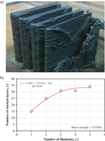
As the height of the build increases, so does the hydrostatic pressure and the layers compress under self-weight. It is common practice to maintain a constant layer height during printing and so the distance between the nozzle and the working surface increases, causing the shape of the filament to change, potentially effecting layer adhe-sion[22]. The effect is exacerbated with every additional layer as the distance between the nozzle and working surface grows eventually causing thefilament to ‘snake’ as it is deposited, leading to buckling of the structure and eventually collapse,Fig. 5. In this example, a 9 mm circular extrusion was used at a layer height of 6 mm and the number of adjacentfilaments per layer was varied and the part is built vertically to test stability, or effective stiffness[13].
Tall structures which must be manufactured in a vertical orientation (Fig. 2 d, for example) are particularly affected and early-age me-chanical behaviour [24]and modelling[25]are of interest. Two ap-proaches to alleviate buildup rate problems have been suggested: the dynamic adjustment of the nozzle height during printing[23]; and the careful control of buildup rate, which may include the addition of ac-celerators injected prior to extrusion to speed up the hardening of lower layers such that they are capable of maintaining the progressively in-creasing load [12,26]. In this issue, Roussel[27]introduces a set of requirements for printable concrete in order to prevent the strength-based failure of the element during the printing process.
3.4. Measurement of properties
The robustness of 3DCP is dependent on achieving repeatable and consistent rheological properties prior to and during printing, making
measurement critically important. Currently, plastic viscosity, yield stress, and thixotropy measurements are made using rotational or os-cillatory rheometry but these methods can be problematic for the evaluation of the materials used in 3DCP which have a high yield stress and viscosity. In addition, they are not easily incorporated as an in-line measurement that can generate feedback during mixing and printing operations.
A common tool in rheometry is the cone and plate. This provides a constant shear rate throughout the diameter, however the smooth surface of the cone results in a wall-slip effect when used with dense suspensions such as cement-based materials[28]. The gap of a cone and plate geometry isfixed by the truncation of the cone and often these truncations result in gaps that are too small for cement paste and par-ticles become stuck between the bottom plate and the cone. A serrated parallel plate geometry can be used to alleviate this issue, which re-duces the wall slip effect, but produces a poorly defined gap between the upper and lower plate and a calibration procedure must be used to obtain the correct shear rate[29].
Rheometry of cement-based materials with aggregates on the order of 1 mm and larger is often carried out using a vane and cup geometry, but this too suffers from a wall slip phenomena. Shear particle migra-tion moves the large aggregates from the vane toward the outer edges of the cup producing a measured viscosity lower than expected from the material. A double helix geometry can be used to create aflow profile
Fig. 4. Deformation at the bottom layer, measured atfive locations indicated in a), of a concrete mix with yield stress of (0.59 ± 0.08) kPa and plastic viscosity of (38.7 ± 4.5) Pa.s, printed at a linear speed of 30 mm/s with cross-section of 40 mm × 10 mm. The plotted points in b) represent the expected range of bottom layer displacement for a given number of stacked layers.
that includes movement of the larger particles, but particle migration does still occur[30], resulting in the development of standard reference materials for mortar and concrete[31].
Within 3DCP research, novel techniques have been adopted and proven to be reliable, such as hand held rotational rheometer mea-surements used in [13]. Techniques such as ultrasonic pulse velocity (UPV) and penetrometer tests may also prove useful. A promising ap-proach is to use Large Amplitude Oscillatory Shear (LAOS). It is used to measure complex viscoelastic modulus (G = G′ + iG″) as of as a func-tion of hydrafunc-tion time. Measurements are made with a stress controlled rheometer with serrated parallel plate geometry. By increasing the amplitude of the applied stress, theflow stress can be measured as the stress where real (G′) and imaginary (G″) components of the viscoe-lastic modulus are equal [32]: at which point the magnitude of the strain developed in the sample is large enough to cause irreversible deformation of the microstructure.
In parallel, the printability of the material is evaluated by printing a series of singlefilament stacks.Fig. 6a depicts this process for a test to evaluateflow stress on a cement paste containing a limestone powder. The print quality changes with time where t = 0 is when cement and waterfirst come into contact. At 6 min after mixing, the yield stress of the mixture is too low to support the mass of the material deposited above. It develops until at 60 min, the material has reached a state where it is able to support multiple deposited layers. Continuing the test on this mix finds that the desirable behaviour is maintained through 80 min until at 99 min, the plastic viscosity has reached a point where pumping is difficult. This test can be used to determine the open time for a particular mix, which here was 37 min.
Fig. 6b shows a representative LAOS measurement, for the same
mixture, where theflow stress point, the stress at which G′ = G″, is plotted in Fig. 6c. At 69 min, the rate of increase of theflow stress increases by 50 times. It is around this point that the material is suitable for 3D printing processes.Fig. 6d and e shows cross sections of the two prints at t = 80 min (after theflow stress transition point) and t = 60 min: cold joints are evident in the former; whereas in the latter, they are not.
Testing methods to identify the open time of different mix designs for 3DCP build on existing work, such as[33]. These methods are cri-tically important for 3DCP as they will provide the constraints to feed into the selection/optimisation of tool path and machine operation parameters in order to minimise, if not eliminate, cold joint formation during the manufacture of components.
4. Issues part II: hardened state
Printed material can be as strong as cast material and it is possible to achieve greater material density than cast equivalents[35], however the reproduction of‘as-good-as-cast’ properties on a commercial man-ufacturing scale has yet to be demonstrated. Creating solid objects from a conglomeration of extrudedfilaments predisposes printed objects to anisotropy which influences end use performance. Understanding these effects such that they can be minimised is a key driver for research currently and are explored here through the following topics:
•
layer adhesion;•
bulk density and under-filling;•
tensile reinforcement;•
shrinkage and durability; and•
measurements of hardened material properties. 4.1. Layer adhesionThe problem is principally generated through the creation cold joints between layers where the cycle-time is too great [22,35], al-though effects such as sand particle size have also been shown to affect layer adhesion in geopolymer mixes[36]. Work using Scanning Elec-tron Microscopy (SEM) has found that interlayer adhesion can be; weakly bonded, weakly bonded due to shrinkage or carbonation, tem-porary weakly bonded, or strongly bonded[37]. Cold joints may be temporary as the interlayer adhesion strength increases as cement hy-dration progresses.
The layer cycle-time is dependent upon the geometry being printed and the process parameters. The determination of the impact of the manufacturing process on the layer cycle-time and consequently on component strength will become an intrinsic component of the design process for structural components. It is likely to require iteration/op-timisation and co-simulation of the manufacturing process during the design of the component in order to ensure the requisite performance is attainable.
4.2. Bulk density and under-filling
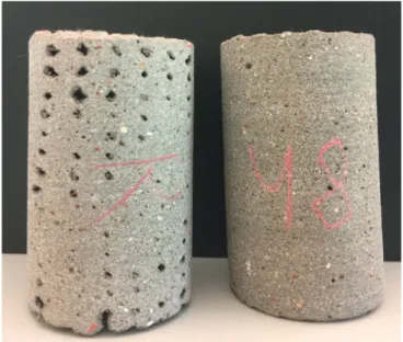
There are additional parameters to consider for geometries that require density to be‘as-good-as-cast’ (e.g.Fig. 2c). Under-filling can create voids within components, depicted inFig. 7(left) next to the desired print quality on the (right), reducing the effective density and potentially to the determent of durability.
The generation of voids from under-filling was first identified by Le et al.[35]and more recently highlighted by Panda et al. [38]. Void creation is dependent on the mix design and stability of rheological properties during printing because this effects the characteristic shape offilament as it is extruded. Deformation of the printed material plays a role in pushing material into these voids to minimise their occurrence, to produceFig. 7(right).
The tool path can also influence under-fill because for a given
Fig. 5. An empirical buildability test geometry where a) the number of adjacent filaments per layer is varied for a part that is built vertically to test stability; such test enables to determine b) the relation between number of adjacent fi-laments and number of stacked layers.
material formulation and nozzle geometry, thefilament is limited to following the radius of a curve during a direction change. The radii that can be accommodated without fracturing or creating a defect is a function of the wet properties, the size and geometry of the nozzle and the speed of deposition. Fig. 8 demonstrates the effect of direction changes on bulk density by creating significant under-fill, on what is supposed to be a fully dense layer. These direction change issues also
affect shell-fill and vertical build components [14,18,38].
When solid layers are required, the target geometry must be dis-cretised intofinite volumes, divisible by the filament size, which almost always leads to an approximation to the desired component geometry. As an example, consider a 10 mm × 9 mm extrusion which cannot be arranged to equal a width of 95 mm unless there is some compromise on bulk density, or acceptance of over-fill. It is theoretically possible to
Fig. 6. Changing printability as a function of time as measured using a Large Amplitude Oscillatory Shear technique. (a) A free-standing structure with a layer cross section of 4 mm × 3 mm is possible during a window of time occurring ca. 1.0 h–1.3 h after mixing. (b) Before each print, the flow stress was determined by oscillatory rheology. Typical relative error for viscosity is 7% [34]. (c) As time after mixing increases, the material'sflow stress increases. A free-standing structure occurs at approximately the time at which theflow stress rapidly increases, corresponding to initial setting. (d) Cross sections of the structures built after initial setting time contain defects and apparent cold joints, while the cross section of structures just prior to initial setting (e) do not.
compensate by adjusting the distances between adjacentfilaments (i.e. the tool path) and by modifying the volumeflow rate of the mix, but difficult to achieve in practice with repeatable precision.
Delivering fully dense components is especially complicated for those that are manufactured using conformal print paths, rather than the more typicalflat layers. Lim et al.[21]describe this application for the production of double-curved panels which are manufactured in horizontal orientation (Fig. 2e). Inflat layer applications, the tool path can be repeated layer-on-layer where the area and geometry do not change, but printing curvature in a conformal manner requires different tool paths on every layer, and a different set of volume approximation calculations, which generates a significant computational burden in the processing of the design. A solution is to divide the double-curved surface into a series of sub-surfaces that more closely approximate to planar surfaces and in that way reduce the volume approximation er-rors[21].
4.3. Tensile reinforcement
If 3DCP is to move beyond the creation of aesthetic curiosities and become an integral part of the procurement of buildings, components will need to be tolerant of the significant stresses induced during lifting and installation [39,40]. Tensile reinforcement beyond the capacity of the mortar itself is essential for many practical applications and hence the incorporation of steel or other reinforcement is necessary.
Adding reinforcement as part of the 3DCP process is not trivial. Reinforcement may lie in parallel with the printed layers where it must be encased. Textiles have potential[41], but steel bar will be re-quired for some applications and here, the diameter of the reinforce-ment will influence the layer thickness, and so the extrusion diameter, therefore the volume discretisation of thefilament and hence the tool path. Thefilament diameter may also influence the desired rheology of the wet material, the layer cycle-time and the minimum feature size (described inSection 5.1) that can be replicated during manufacture and so the tolerances that can be achieved which effect the geometrical conformity of thefinished piece.
Reinforcement may also be needed perpendicular to the print layers, which is even more challenging. Novel reinforcement solutions have been proposed including a screw-based system, although there are no published performance characteristics of this system[9]. Conventional reinforcement has been incorporated into printed components using post placement and post tensioning[42]. In this example, the solution was to design in the vertical conduits to be printed into the component into which the reinforcement could be placed, tensioned and then grouted into position. The use of a permanent formwork approach (depicted in Fig. 2b) also is able to utilise more conventional re-inforcement techniques that are then printed around, to beflood filled once the printed formwork has cured. This has the added advantage that structural capacity can be designed to conventional codes.
Unconventional methods have been investigated that introduce wire reinforcement into the extruded bead[43], which avoids additional automation of placement with the layer as it is extruded. Thefilament direction can be used to reinforce along tool paths which can be de-signed (in theory at least) to act in the most optimal direction, which may not be in a traditional grid format. Hambach and Volkmer[44] investigated a similar idea, but using the extrusion to orientfibers to align with thefilament, thus increasing its tensile capacity. They also found that the pattern of the tool path used to‘fill in’ solid areas (called ‘hatching’) did effect component strength. Other approaches have been trialled to redesign components that can be reinforced externally during assembly[45]. Asprone et al.[46]in this issue provide a more com-prehensive discussion of reinforcement.
There is still a great deal to be understood about the effect of: printing the encasement of reinforcement; how the encasement is ef-fected by the manufacturing tolerances of reinforcement; and the ability to manufacture reinforcement into the novel shapes that will be re-quired. The arbitrary creation of form is a key value-added driver for the technology and so computational methods that can analyse and optimise structural capacity[47]will need to do so within the con-straints of manufacturing methods that incorporate reinforcement.
4.4. Shrinkage and durability
One advantage of 3DCP is the elimination of formwork, however, doing so removes a barrier between the curing concrete and the sur-rounding environment. Printed components often have a greater ex-posed surface area than with casting and combined with the low water/ cement ratios typically used in 3DCP mortars, the likelihood of cracking resulting from autogenous shrinkage is increased. Mix designs must therefore minimise dimensional changes due to dry and autogenous shrinkage and greater care must be taken while curing. Approaches to the problem in conventional concrete construction include internal curing methods, moist curing, shrinkage reducing admixtures and
Fig. 7. Two samples that represent good quality printing on the right and poor quality on the left. On the left, the outline of eachfilament can be identified, interspersed with inter-filament voids of various sizes, whereas the filaments are indiscernible in the right hand sample.
Fig. 8. The impact of nozzle direction changes on the layer density, causing underfill problems.
shrinkage compensation [48,49]. Marchon et al.[50]discuss these is-sues in greater detail this issue.
4.5. Measurement of hardened properties
The anisotropic nature of 3DCP structures means that there are new opportunities for research to develop new methods of analysis.Table 1 provides details of the papers that have investigated hardened proper-ties as they are effected by filament bonding. Samples tended to be saw cut, or cored from printed material. Some have taken this material from larger pieces manufactured under‘normal print operations' and others configure the printing specifically for testing (namely those who fo-cused on inter layer bonding alone).
There is no consistent format for describing the printing process parameters such as nozzle size, layer height,filament dimensions, print speed, size of component from which the samples are taken, and layer cycle-times. For example, the interlayer pressure changes depending on the design of the process. Le et al.[35]use a 9 mm bead that is de-formed when printing to about 12 mm × 6 mm, hence the interface is subjected to pressures from the pump, whereas[36]state that they use ‘no pressure’ when depositing material (other than that generated by gravity acting on the mass offilament). The discrepancy in reporting process parameters and the variability in test geometry reported in Table 1demonstrate the need for standardised testing methods.
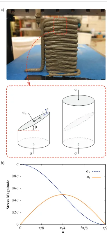
Opportunities for new analytical methods also exist. For example, Fig. 9a shows a 3DCP structure whereby a hypothetical cylindrical core has been removed for uni-axial compression testing. To assess the strength of the cylinder, and by extension, the 3DCP structure, the compression test must probe the defects in the material. In this case, the layer interface. To compute the magnitude of the normal and tangential stresses components on the layer interface, a force balance is applied to a section of the cylinder containing one layer. The magnitude of the normal (σn) and tangential (σt) stress on the interface of a 3DCP
structure can be computed by Eqs. (1) and (2), where σ is the stress vector applied to the surface of the test specimen andn and t are the unit vectors normal and tangential to the layer surface, respectively:
= ⋅ =σ
σn n | |σ cos θ2( ), (1)
= ⋅ =σ
σt t | |σ sin θ cos θ( ) ( ). (2)
Plotting the normal and tangential stresses on the layer interface (Fig. 9b) as a function of the layer angle with respect to the applied stress, shows the shear stress is maximum when the layer angle is at 45° to the applied stress. It is this magnitude of the tangential stress com-ponent that may be the source of failure in 3DCP structures as it will move one layer relative to the next.
It is possible with some 3DCP processes to adjust the orientation of the printed component during building, and by extension, the or-ientation of the print layers to the applied loads when in service. This becomes one of the variables in the manufacturing process that can inform the design and so influence the structural aspects of the com-ponent.
Table 1
Sample dimensions in mm, where:† = not specified and binder types where: GP = geo-polymer, CSA = calcium sulfoaluminate, FA = fly ash, SF = silica fume, OPC = ordinary portland cement.
Ref. Filament Compression (Cube size) Tensile bond Beam (Flexural) Beam (Shrinkage) Type
[35] 9ϕ 100 58ϕ 100×100×400 75×75×229 CEM I, FA, SF [38] 25ϕ 50 † 40×40×160 - GP [22] 20×20, 30×15 ∼ 30×∼90 FA/GP [44] 6×12×60 OPC, SF [43] † 300×50×80 † [37] † 25×25×120 OPC
Fig. 9. (a) A 3DCP structure with a hypothetical cylindrical core removed for compressive strength testing. (b) Normal and tangential stress with in the cy-linder as a function of layer angle.
5. Issues part III: geometric conformity
3DCP, as with any additive manufacturing process, creates a facsi-mile of a 3D model. It is the conformity of the printed part to this geometry that is a fundamental requirement of the manufacturing process. The value of the printed object has a direct relationship to the degree of that can be obtained by a process. Geometries for manu-facture by 3DCP are driven by functional objectives and constrained by process limitations and these are explored here in four sections:
•
minimum feature size and tolerances;•
hatching and creating fully dense components;•
material and process modelling and simulation; and,•
creating overhangs.5.1. Minimum feature size and tolerances
Functional objectives require the reproduction of features, printed to a specified tolerance, and so the size of the extrusion and the layer thickness determines the print resolution, which limits the size of the feature that can be created. The minimum feature size, therefore, be-comes a useful concept to consider since this will limit the geometrical conformity of the 3DCP object to the indented dimensions[51]. The print resolution is constrained, principally, by the fresh properties of the material, the tool path, and process parameters, which are depen-dent upon the build strategy and the stiffness of the structure being built. Functional requirements depend upon the properties of the har-dened material as well as the geometry and effective stiffness.
Functional objectives might include design for some acoustic at-tenuation, or to minimise the thermal transmissivity of a structural component[11]. Work by Godbold et al. [52,53] explored the creation of acoustic absorbers with Fused Deposition Modelling (a thermosetting filament based rapid prototyping technique, similar in principle to 3DCP). Adsorption can be achieved with reflective materials (such as hardened mortar) by using the control of material deposition to form Helmholtz resonator structures. These principles were applied to the creation of a mock up acoustic adsorption panel printed at Loughbor-ough University and depicted in Fig. 10. The consequences of this functional geometry are an increase in the precision of manufacture: i.e. the reproduction of smaller feature sizes, resulting in increased print resolution, which in turn reduces volumetric deposition rate and print speed.
Control of geometry has been applied to minimise the thermal conduction path in wall elements in order to reduce thermal transi-tivity[1]. Test panels were produced using 3D printing (gypsum/binder based process) and subjected to a certified guarded hot-box test. The effectiveness of reducing the conductive heat path was demonstrated and a thermal conductivity of 0.1 W/mK was achieved, at least as good as aerated concrete[1].
The print resolution is constrained by material rheology and nozzle dimensions limiting the achievable print tolerances. These tolerances are often larger than those required for component interfaces and sur-face finishing in construction applications. Techniques have been ap-plied to improve this, such as using automated troweling to smooth the vertical surface of a wall being printed[54]. Improvement to the tol-erances of double-curved working surfaces can be improved sig-nificantly by printing conformally using 4 or 5 axis movement to maintain a tangential position of the nozzle to the working surface[21]. But such approaches have limitations and those components that re-quire higher manufacturing tolerances must use 3DCP to create a near-net-shaped object, i.e. close to the desired (net-shape) geometry, and then an additional additive (rendering) or subtractive (cutting/milling/ grinding) process to achieve the required precision[21].
5.2. Hatching and creating fully dense components
It is common practice in conventional additive manufacturing to improve tolerances and surface finish of a printed component by printing boundary paths that circumnavigate the outer edges of a component and any internal features, which can be seen inFig. 8. The solid part of the component is then left to be‘hatched’, or filled in with material. These hatching patterns are described by the tool-path and can have a significant impact on the bulk density (Section 4.2) because of directional changes (potentially increasing the likelihood of under-filling) and potentially increasing over-filling due to excessive stop/ start operations that can cause material to accommodate, exemplified in (Fig. 11).
Hatching patterns developed for conventional additive manu-facturing are often not appropriate for 3DCP because they do not ac-count for these process constraints [11,21]. Work is needed to develop these codes, as well as the development of geometry capture, both during build and for conformity verification [25,42].
5.3. Material and process modelling and simulation
Geometry that is more challenging to manufacture can be generated through the application of structural optimisation[47]. This technique has become well-established in the field of structural mechanics, especially when associated with finite element simulation. Classical methods, SIMP (Solid Isotropic Material with Penalisation[55]), for
Fig. 10. Creating additional functionality by incorporating Helmholtz re-sonators inside a 3DCP panel.
example, rely on node-based values to evaluate and optimise the geo-metry. The optimisation procedure consists of determining at each element if it should either stay or be removed. The SIMP technique has been applied at different scales: to the design of efficient building structures[56]; or as a tool for designing micro and nano-architectured materials [57]. Such approaches are being increasingly adopted by architecture and to some extent being driven by the development of 3DCP and Building Information Modelling.
These issues signal a greater use of multi-physics based modelling tools where the elastic stability of the component can be evaluated, alongside the kinetics of hydration, the evolving viscoplasticity of fresh cement and the evolution of temperature within the printing environ-ment. Although these phenomena can be modelled individually, cou-pling them with process simulation to predict the hardened properties of a component is extremely challenging and remains an aspiration for the 3DCP component design process.
5.4. Creating overhangs
Certain components require overhanging sections, or even the creation of voids within the solid geometry. These can be created in two ways: either by corbeling (cantilevering)[18]and[11], or by the ad-dition of some temporary support that can be printed over and then removed on completion, as used in the manufacture of the panels de-picted inFig. 2,[21]. Some degree of corbeling is possible, but this can become unstable particularly when corbeling a singlefilament struc-ture. This is in part due to the material properties, but also to do with the way in which the machine positions the nozzle[11].
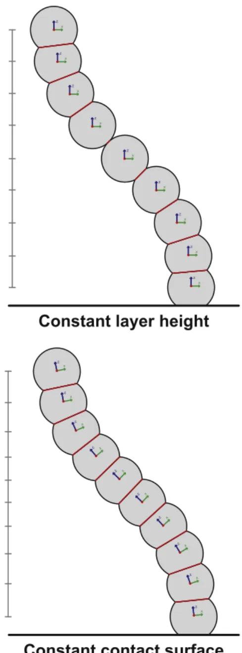
For example, 3D-to-2D slicing, which is by far the most common method adopted, yields planar layers of equal thickness built on top of each other. This approach is not optimal from a design and structural viewpoint, as it will induce cantilevers when two consecutive layers have different sizes and limit the attainable geometries. The tangential continuity method optimises the structure being built by creating layers of varying thickness[11]. These layers exhibit a maximised surface area of contact between each other, hence stabilising the overall structure. Moreover, this method is actually exploiting the possibilities of the process in terms of printing speed andflow for generating variations in the layer thickness as depicted inFig. 12. This highlights the compli-cations that the geometrical design might impose on a build, but also how clever algorithmic methods to compensate for material properties can enable more freedom in the design.
6. Application factors
From the preceding discussion, it becomes evident that the solutions that will improve process robustness, geometrical conformity and har-dened properties are on a spectrum, with control of the material properties and limitations on component design at one end and the sophistication of the process and its control at the other. There are 5 primary issues to consider:
•
workability of the fresh mix;•
deformation of the placed material;•
hardened properties of the conglomerated component;•
conformity to the desired geometry; and,•
geometrical freedom in design afforded through the process. The design performance of the component is directly related to the hardened properties of the material (or composite). Some factors effect the rate of manufacture (controlled setting applied to a compression only, vertical build, for example) rather than design.Table 2lists theseFig. 11. The impact of nozzle start/stop operations on the deposited layer vo-lume, causing overfill which contributes to deformation and conformity issues.
Fig. 12. Schematic cut perpendicular to layers 3D printed using the cantilever method commonly found in commercial 2D slicing software (left) and the tangential continuity method (right).
issues and relates them to important aspects of the material, design and process.
One can envision a process that is manufacturing component (or ‘continuous') geometries to within an acceptable geometric conformity and that the component has the desired performance characteristics (or hardened properties). The translation of that design into machine op-erations, the operational parameters of the process and the material properties will therefore all have a role to play in the robustness of the manufacturing process.
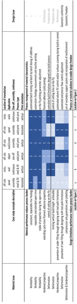
Table 2describes these factors in two blocks, one that describes the spectrum created when considering what developments in material science can be delivered in terms of reducing the reliance on clever process control to manage inconsistencies in the material. The second considers the complexity of design geometry and conformance: the simpler and less precise that design, then the more tolerant we can be over the lack of precision and robustness that the materials and process can produce.
Reflecting on the consequences for a specific applications, the cen-tral proportion ofTable 2takes the six examples inFig. 2and ranks the importance of the issue to the manufacture of that type of component. Although subjective, an attempt is made to rank importance on a scale of 0–3 where: 0, negligible use for the approach and example applica-tion; 1, occasionally of use, probably depends on the specifics of the component; 2, where it would improve process performance, but may not be essential to success, or there may be workarounds that can be readily applied; and 3, essential for the success of the application, the benefits would be realised with every component manufactured.
The application will dictate the materials and process research re-quired and at the heart of the process lies the control and treatment of the material in its fresh state. Issues such as under and over-filling tend to effect solid geometries replicating ‘as-good-as-cast’ material, whereas controlling the setting of material tends to effect applications linked to the manufacture of vertical wall/shell structures. The creation of overhanging structures and special features for aesthetics and function are again limited to subsets of components and the precision required in printing will therefore effect these applications to a far greater extent those where conventionalfinishing might be applied, such as rendering printed walls. This returns to the question of value and in a wall structure this might be in the rapidity of build to reduce cost, where the precision is less of an issue. In panel assemblies and other components, the high precision and qualityfinish will have a much more significant impact and will influence both the development of the capabilities of the process and the ultimate commercial market these components are di-rected towards.
7. Conclusions and future vision
Through a reflective critique of the literature combined with new insights from ongoing work in the UK, France, Denmark and the USA, this paper attempts to draw together the technological issues that effect extrusion-based 3DCP and disentangles the critical interdependencies between the materials, manufacturing and design processes. Solutions to some of these issues have been presented and research areas have been identified to establish the current state-of-the-art.
The commercial success of 3DCP lies in the robustness of the design and manufacturing process, the ability for architects and engineers to design certifiable components and building elements and in the value of the manufactured components. Although the value of automation to the industry lies with the health of an aging workforce and dealing with skilled labour shortages, the value of the component is dictated by its quality. Quality is created by manufacturing precision, material per-formance and in some components, the aesthetic: ever more so in the current age of personalisation and adaptation of design for individual cases. 3DCP can potentially provide‘value added’ through the design of additional functionality and digitally controlling the manufacturing process. Table 2 Matrix of materials and design related issues as they relate to the methods and applications described in Fig. 2 , highlighting the spectrum of materials and process development for each and describing the range of design limitations and freedoms that may be desirable in commercially successful processes.
Recognising that the design is the end goal, and that the materials underpin the success of manufacture, we offer a vision to inspire and guide the future research effort in the field of 3DCP:
Design of components will be generated through optimisation of component geometries using co-simulation, coupling the modelling of the manufacturing process (tool path generation) with a model of the material characteristics both fresh and hardened (described through standardised testing) to generate a structural performance model based on hardened properties. It will include optimal design for reinforcement.
Finishing: net-shape CAD geometry will be used to create the near-net-shape to be printed, such that thefinishing operations can be minimised enabling greater precision to be achieved.
Process: there will be a number of manufacture specific components for particular applications. These will become standardised such that the optimal configuration for a particular mix characteristic can be readily implemented and that reinforcement and other materials can be placed to fabricate composite materials. These operational parameters will be modelled as plug-ins in the design software to allow designers autonomy of manufacture.
Materials: these will be developed to provide repeatable fresh properties, using different aggregates. The open-time will be stable and repeatable. Setting will be controllable to a fine degree. The bonding of adjacent material will become stronger and will be en-abled to occur over a long period to maximise the operation window. They will not be described by mix, but by aesthetic and hardened properties. Standardised testing will be adopted in order to characterise materials to enable international designs to be manufactured anywhere on the planet.
Acknowledgements
This piece of collaborative was made possible through experience gained by the authors working on funded research past and present. The UK would like to acknowledge the initial project funded through the Loughborough University IMCRC (EPSRC grant number: EP/ E002323/1, 2006-2011) and the support of the current Innovate UK funded project CAMBER (EPSRC grant number: EP/P031420/1). Denmark wishes to acknowledge the Danish Agency for Science and Higher Education for funding the project‘3D Printet Byggeri’ at the Danish Technological Institute.
References
[1] R. Buswell, R. Soar, A. Gibb, A. Thorpe, Freeform construction: mega-scale rapid manufacturing for construction, Autom. Constr. 16 (2007) 224–231.
[2] P. Wu, J. Wang, X. Wang, A critical review of the use of 3-D printing in the con-struction industry, Autom. Constr. 68 (2016) 21–31.
[3] J. Pegna, Exploratory investigation of solid freeform construction, Autom. Constr. 5 (1997) 427–437.
[4] N. Labonnote, A. Rønnquist, B. Manum, P. Rüther, Additive construction: state-of-the-art, challenges and opportunities, Autom. Constr. 72 (2016) 347–366. [5] N. Hack, W. Lauer, S. Langenberg, F. Gramazio, M. Kohler, Overcoming repetition:
robotic fabrication processes at a large scale, Int. J. Archit. Comput. 11 (2013) 285–299.
[6] E. Lloret, A.R. Shahab, M. Linus, R.J. Flatt, F. Gramazio, M. Kohler, Complex concrete structures: merging existing casting techniques with digital fabrication, Comput. Aided Des. 60 (2015) 40–49.
[7] G.J. Gibbons, R. Williams, P. Purnell, E. Farahi, 3D Printing of cement composites, Adv. Appl. Ceram. 109 (2010) 287–290.
[8] D. Lowke, E. Dini, A. Perrot, D. Wenger, C. Gehlen, B. Dillenburger, Particle-bed 3D printing in concrete construction– possibilities and challenges, Cem. Concr. Res. 112 (C) (2018) 50–65.
[9] B. Khoshnevis, Automated construction by contour crafting–related robotics and information technologies, Autom. Constr. 13 (2004) 5–19.
[10] G. Cesaretti, E. Dini, X. De Kestelier, V. Colla, L. Pambaguian, Building components for an outpost on the lunar soil by means of a novel 3D printing technology, Acta Astronaut. 93 (2014) 430–450.
[11] C. Gosselin, R. Duballet, P. Roux, N. Gaudillière, J. Dirrenberger, P. Morel, Large-scale 3D printing of ultra-high performance concrete - a new processing route for architects and builders, Mater. Des. 100 (2016) 102–109.
[12] T. Wangler, E. Lloret, L. Reiter, N. Hack, F. Gramazio, M. Kohler, M. Bernhard, B. Dillenburger, J. Buchli, N. Roussel, R.J. Flatt, Digital concrete: opportunities and challenges, RILEM Tech. Lett. 1 (S.I.) (2016) 67–75.
[13] T. Le, S. Austin, S. Lim, R. Buswell, A. Gibb, T. Thorpe, Mix design and fresh properties for high-performance printing concrete, Mater. Struct. 45 (2012) 1221–1232.
[14] Z. Ahmed, F. Bos, R. Wolfs, T. Salet, Design considerations due to scale effects in 3D concrete printing, Proceedings of 8th International Conference of the Arab Society for Computer Aided Architectural Design (ASCAAD 2016), 2016 London, U.K.. [15] L.N. Thrane, C. Pade, C.V. Nielsen, Determination of rheology of self-consolidating
concrete using the 4C-Rheometer and how to make use of the results, J. ASTM Int. 7 (1) (2009) 1–10.
[16] S. Lim, R. Buswell, T. Le, S. Austin, A. Gibb, T. Thorpe, Developments in con-struction-scale additive manufacturing processes, Autom. Constr. 21 (2012) 262–268.
[17] L. Reiter, T. Wangler, N. Roussel, R.J. Flatt, The role of early age structural build-up in digital fabrication with concrete, Cem. Concr. Res. 112 (C) (2018) 86–95. [18] F. Bos, R. Wolfs, Z. Ahmed, T. Salet, Additive manufacturing of concrete in
con-struction: potentials and challenges of 3D concrete printing, Virtual Phys. Prototyp. 11 (2016) 209–225.
[19] W.R.L. da Silva, 3D Concrete Printing: From Material Design to Extrusion, (2017) Presentation Slides.
[20] W.R.L. da Silva, 3D Printed Constructions - Engineering Perspective, (2017) Presentation Slides.
[21] S. Lim, R. Buswell, P. Valentine, D. Piker, S. Austin, X. Kestelier, Modelling curved-layered printing paths for fabricating large-scale construction components, Addit. Manuf. 12 (2016) 216–230.
[22] B. Panda, S.C. Paul, N.A.N. Mohamed, Y.W.D. Tay, M.J. Tan, Measurement of tensile bond strength of 3D printed geopolymer mortar, Measurement 113 (2018) 108–116.
[23] R.J.M. Wolfs, F.P. Bos, E.C.F. van Strien, T.A.M. Salet, A Real-Time Height Measurement and Feedback System for 3D Concrete Printing, Springer International Publishing, Cham, 2018, pp. 2474–2483, https://doi.org/10.1007/978-3-319-59471-2_282.
[24] R. Wolfs, F. Bos, T. Salet, Early age mechanical behaviour of 3D printed concrete: numerical modelling and experimental testing, Cem. Concr. Res. 106 (2018) 103–116.
[25] T. Salet, F. Bos, R. Wolfs, Z. Ahmed, 3D concrete printing-a structural engineering perspective, High Tech Concrete: Where Technology and Engineering Meet, Springer, 2018.
[26] A. Perrot, D. Rangeard, A. Pierre, Structural built-up of cement-based materials used for 3D printing extrusion techniques, Mater. Struct. 49 (2016) 1213–1220. [27] N. Roussel, Rheological requirements for printable concretes, Cem. Concr. Res. 112
(C) (2018) 76–85.
[28] A. Saak, S. Shah, The influence of wall slip on yield stress and viscoelastic mea-surements of cement paste, Cem. Concr. Res. 31 (2001) 205–212.
[29] C.F. Ferraris, M. Geiker, N.S. Martys, N. Muzzatti, Parallel-plate rheometer cali-bration using oil and computer simulation, J. Adv. Concr. Technol. 5 (2007) 363–371.
[30] A. Olivas, M.A. Helsel, N.S. Martys, C.F. Ferraris, W.L. George, R. Ferron, Rheological measurement of suspensions without slippage: experiment and model, (2016),https://doi.org/10.6028/NIST.TN.1946NIST Technical Note 1946. [31] A. Olivas, C.F. Ferraris, N.S. Martys, W.L. George, E.J. Garboczi, B. Toman,
Certification of SRM 2493: Standard Reference Mortar for Rheological Measurements, (2017),https://doi.org/10.6028/NIST.SP.260-187NIST SP 260-187.
[32] T.G. Mezger, The Rheology Handbook, 4th ed., Vincentz Network, Hanover, Germany, 2014.
[33] L. Mettler, F. Wittel, R. Flatt, H. Herrmann, Evolution of strength and failure of SCC during early hydration, Cem. Concr. Res. 89 (2016) 288–296.
[34] A. Olivas, C.F. Ferraris, W.F. Guthrie, B. Toman, Re-certification of SRM 2492: Bingham Paste Mixture for Rheological Measurements, (2015),https://doi.org/10. 6028/NIST.SP.260-182NIST SP-260-182.
[35] T. Le, S. Austin, S. Lim, R. Buswell, R. Law, A. Gibb, T. Thorpe, Hardened properties of high-performance printing concrete, Cem. Concr. Res. 42 (2012) 558–566. [36] B. Zareiyan, B. Khoshnevis, Interlayer adhesion and strength of structures in
con-tour crafting - effects of aggregate size, extrusion rate, and layer thickness, Autom. Constr. 81 (2017) 112–121.
[37] V.N. Nerella, S. Hempel, V. Mechtcherine, Micro- and macroscopic investigations on the interface between layers of 3D-printed cemontitions elements, Proceedings of the International Conference on Advances in Construction Materials and Systems, 3-8. 9. 2017), 2017 Chennai, India.
[38] B. Panda, S.C. Paul, L.J. Hui, Y.W.D. Tay, M.J. Tan, Additive manufacturing of geopolymer for sustainable built environment, J. Clean. Prod. 167 (2017) 281–288. [39] R. Duballet, O. Baverel, J. Dirrenberger, Classification of building systems for
concrete 3D printing, Autom. Constr. 83 (2017) 247–258.
[40] R. Duballet, O. Baverel, J. Dirrenberger, Design of Space Truss Based Insulating Walls for Robotic Fabrication in Concrete, Springer Singapore, Singapore, 2018, pp. 453–461,https://doi.org/10.1007/978-981-10-6611-5_39.
[41] J. Hegger, M. Curbach, A. Stark, S. Wilhelm, K. Farwig, Innovative design concepts: Application of textile reinforced concrete to shell structures, Struct. Concr. 1 (2017) 1–10.
[42] S. Lim, R. Buswell, T. Le, R. Wackrow, S. Austin, A. Gibb, A. Thorpe, Development of a viable concrete printing process, Proceedings of the 28th International Symposium on Automation and Robotics in Construction (ISARC2011), 2011, pp. 665–670 Imperial Palace Hotel, Seoul, South Korea.
[43] F. Bos, Z. Ahmed, R. Wolfs, T. Salet, 3D Printing concrete with reinforcement, High Tech Concrete: Where Technology and Engineering Meet, Springer, 2018, pp. 2484–2493, ,https://doi.org/10.1007/978-3-319-59471-2_283.
[44] M. Hambach, D. Volkmer, Properties of 3D-printedfiber-reinforced Portland ce-ment paste, Cem. Concr. Compos. 79 (2017) 62–70.
[45] B. Butler-Millsaps, WASP Makes Progress on House 3D Printing With Modular Printed Reinforced Concrete Beams, (2015) https://3dprint.com/88467/wasp- makes-progress-on-house-3d-printing-with-modular-printed-reinforced-concrete-beams/.
[46] D. Asprone, C. Menna, F. Bos, T. Salet, J. Mata-Falcon, W. Kaufmann, Rethinking reinforcement for digital fabrication with concrete, Cem. Concr. Res. 112 (C) (2018) 111–121.
[47] P. Martens, M. Mathot, F. Bos, J. Coenders, Optimising 3D Printed Concrete Structures Using Topology Optimisation, Springer International Publishing, Cham, 2018, pp. 301–309,https://doi.org/10.1007/978-3-319-59471-2_37.
[48] D.P. Bentz, W.J. Weiss, Internal Curing: A 2010 State-of-theArt Review, (2011) NIST IR 7765.
[49] D.P. Bentz, S.Z. Jones, M.A. Peltz, P.E. Stutzman, Mitigation of autogenous shrinkage in repair mortars via internal curing, Concr. Aust. 41 (2015) 35–39.
[50] D. Marchon, S. Kawashima, H. Bessaies-Bey, S. Mantellato, S. Ng, Hydration and rheology control of concrete for digital fabrication: Potential admixtures and ce-ment chemistry, Cem. Concr. Res. 112 (C) (2018) 96–110.
[51] R. Buswell, T. Thorpe, R. Soar, A. Gibb, Design data issues for the control of mega-scale rapid manufacturing, Proceedings of the 24th CIB W78 Conference‘Bringing ITC knowledge to work’, 2007 Maribor, Slovenia.
[52] O. Godbold, R. Soar, R. Buswell, Implications of solid freeform fabrication on acoustic absorbers, Rapid Prototyp. J. 13 (5) (2007) 298–303.
[53] O. Godbold, J. Kang, R. Buswell, R. Soar, Fabrication of acoustic absorbing topol-ogies using rapid prototyping, Can. Acoust. 36 (2008) 144–145.
[54] B. Khoshnevis, D. Hwang, K. Yao, Z. Yeh, Mega-scale fabrication by contour crafting, Int. J. Ind. Syst. Eng. 1 (2006) 301–320.
[55] M.P. Bendsoe, O. Sigmund, Topology Optimization: Theory, Methods and Applications, Springer Verlag, 2003.
[56] C. Cui, H. Ohmori, M. Sasaki, Computational morphogenesis of 3D structures by extended ESO method, J. Int. Assoc. Shell Spat. Struct. 44 (2003) 51–61. [57] S. Zhou, Q. Li, Design of graded two-phase microstructures for tailored elasticity