Science Arts & Métiers (SAM)
is an open access repository that collects the work of Arts et Métiers Institute of Technology researchers and makes it freely available over the web where possible.
This is an author-deposited version published in: https://sam.ensam.eu
Handle ID: .http://hdl.handle.net/10985/10154
To cite this version :
Xavier GODOT, Alain ETIENNE, Ali SIADAT, Patrick MARTIN - Methodology to develop a geometric modeling process according to collaborative constraints - International Journal on Interactive Design and Manufacturing p.1-18 - 2014
METHODOLOGY TO DEVELOPP A GEOMETRIC MODELING
PROCESS ACCORDING TO COLLABORATIVE CONSTRAINTS
Xavier GODOT (Ph.D), Alain ETIENNE (Ass. Pr), Ali SIADAT (Ass. Pr), Patrick MARTIN (Pr) Laboratoire Conception Fabrication Commande (LCFC), Centre Arts et métiers ParisTech 57078 METZ, France
Abstract: A product design goes through a Digital Mock-Up which is based on the product geometric model. This latter has an important role in the design project whose exploitation mainly depends on how it has been established [1]. Furthermore, the growing competitive context hardly encourages firms to implement new working methods like collaborative engineering. However, its implementation in combination with product geometric data generates many problems in terms of project and data management. For this purpose, this article proposes a methodological solution to the problem at hand. Moreover the problem gets complicated as the project progresses. As a result, the detailed design phase becomes critical particularly in the face of this problem. Therefore, the current article focuses on this phase of the product design process through an example. Keywords: Interactive design, Collaborative engineering, design process, data management, CAD
1 Introduction and context of the
study
The mechanical industry faces to a hard competition and it must find new solutions to increase its competitiveness. In a firm, it depends on a lot of elements (commercial, organizational, technical…). In the technical domain, innovative product design project must be as efficient as possible to meet the design aims in terms of cost, delay and performances.
This efficiency depends on the quality
(relevance, consistency, genericity,…) of
knowledge and expertise implemented, but it also depends on the quality of collaborations (meaning of objects, methodology, give the relevant information at the good moment) and
interactivity between designers. So, it is
important to manage project and data together. Use of complex and heterogeneous design tools (sketches, drawings, rules, CAD and simulation software for example) makes this task very difficult.
In this context, the question understudy is how to coordinate and control a design project (in terms of design cost and delay) while ensuring the better level of collaboration and
interactivity between all contributors. This
study is mainly focused on the detailed design phase since data generated at this stage are large in number, more complex and more difficult to manage. This issue stems from their
heterogeneity and their high degree of
relationship [2] [3]. CAD data are at the heart of the problem. So, we propose to integrate
project and data management. The aim is to build a design strategy allowing the creation of CAD data answering to project requirements [4] [5] [6].
So, this article is composed of two sections. The first one shows the methodology and dedicated tools used to deduce a geometric modeling process from a design strategy. The whole is illustrated through an example. The second part is the implementation of the latter
to design a product and study the
manufacturing of a part.
2 Proposed methodology
The only way to solve this issue is taking
in account collaborations and interactions
covering all the aspects of the product development (creation, calculation, simulation, modelling…). Many methods exist, but each one treats only one aspect [7] [8] [9]. The solution could be an assembly of all those methods. However it will be difficult ensuring consistency of the whole.
So, the proposed methodology results from a global approach taking simultaneously into account all aspects of this issue. It consists to build a Provisional Product Design Process (called PPDP) to coordinate and control the product design project. This PPDP is made of four major steps:
1. Identify the different constituent parts of the PPDP.
2. Formalize the know-how describing
3. Transform the independent and heterogeneous processes into a single one adapted to collaborative work. 4. Extract elements allowing building a
geometric model process.
2.1 Identify different constituent parts of the PPDP
The different parts of the PPDP are identified from the product lifecycle. This one must be consider in a design point of view. In
this case, several stages are usually
distinguished: manufacturing, use, sale
(transport, storage...), maintenance and
recycling [11]. Theoretically, all stages have to be taking into account to design a product exhaustively. But practically, designers just consider use and manufacturing stages because they constitute the better compromise between the cost, the delay and the definition level of the product.
The example developed in this article is an illustration of this case since it requires an
intensive useful of CAD software.
Consequently, the list of disciplines is the following:
The product functional design meeting
functional specifications (use stage).
The manufacturing study creating all of the
data required to manufacture each product’s component (manufacturing stage).
2.2 Formalize the know-how describing each part [11]
In this second step, each product lifecycle stage previously identified is detailed into a specific process [12]. To perform this work, two elements are needed to be defined:
The formalization language.
The granularity of the process and its
data flows.
The formalization language has to model all required elements to realize a product design
project. These elements are mainly: the
activities description, input and output data flows, human and material resources, links of prior to each process activity. Moreover, this language has to be easy to understand and it should not require specific knowledge to be used by anyone, especially experts of the
process themselves. Considering these
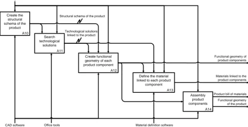
requirements, the language chosen is IDEF0. Figure 1 shows one IDEF0 model of work processes corresponding to both disciplines chosen.
Figure 1(a): Initial formalization of functional design following the language IDEF0.
A10 Create the structural schema of the product A12 Create functional geometry of each product component A13 Define the material linked to each product
component A14 Assembly product components Functional specifications
Structural schema of the product
Functional geometry of product components
Functional geometry of the product Materials linked to the product components
CAD software Material definition software
A11 Search technological
solutions
Technological solutions linked to the product
Office tools
Manufacturing study (b)
Figure 1(b): Initial formalization of manufacturing study following the language IDEF0.
Concerning the second point, the
granularity of process and its data flows, it allows defining a system of references used to homogenize the processes initially created (see
Fig 1). Indeed, the result of previous
formalization work depends on the person who did it. Moreover, in the next steps activities coming from different processes are linked. That is why the activities are desired to be of the similar size. In order to perform this
transformation, three dedicated rules are
defined:
The rules 1 and 2 define the activity
size to ensure a uniform granularity in work processes.
The rule 3 controls the data flow size to
ensure all the activities composing
processes have uniform characteristics. To define the first rule, we observed the design work and more precisely the « detailed design activity ». We deduced from these observations that it consists of five kinds of tasks:
« Create » which is the creativity aspect
of a design activity ( a technological solution in this case)
« Calculate » to dimension the product.
« Represent » to model and depict
design data (a geometric model for example). These description data are used or enriched in order to completely describe the product.
« Evaluate/Optimize » to control the
product matches to functional
requirements.
« Validate » to decide if the project
must be continued or modified.
The Figure 2 illustrates these five kinds of data and their relationships. Hence, an activity of the detailed design process must follow this
sequencing: creation, calculation,
representation, evaluation/optimization and
validation. Concerning the last step, it is possible to add new specifications coming from the validation analysis. It is also important to notice that each detailed design activity can only communicate with the others through its description data.
A21 Design the roughing tools for each product component
A23 Create the roughing geometry of each product component
A27 Create the the final geometry of each product component
Manufacturing specifications (roughing)
Final geometry of each product component Roughing tools
geometry of each product component
Roughing geometry of each product component
A20 Design the roughing manufacturing process
of each product component
A25 Design the finishing manufacturing process of each product component
Software to design manufacturing processes Functional surfaces geometry of product basic components Functional geometry of product basic components A26 Design the finishing tools of each product component
Finishing tools geometry of each product component Manufacturing
specifications (finishing) Functional geometry of
product basic components Functional surfaces geometry of product basic components
A24 Characterize the material linked to the roughing of each
product component
A28 Characterize the material linked to the finishing step of
each product component
Material definition software Materials characteristics linked
to the product basic components
Material linked to each product component A22 Dress-up the roughing tools of each product component Roughing tools functional geometry of each product component
Roughing manufacturing process of each product component
A29 Assembly product basic component in their final
definition Product final geometry CAD software + sizing software + simulation software
Finishing manufacturing process of each product component Material characteristics answering to functional requirements and allowing to manufacture the roughing
Figure 2: illustration of detailed design activity with its interactions and its integration in the provisional product design process.
So, an activity is integrated into a process only if it generates these three kinds of data. If not, the activity is too detailed and it requires to be merged with another one until it satisfies the rule. When this rule is applied on our case
study, the activity A12 in the process
« functional study » does not generate design data. Indeed, it uses design data coming from the activity A11. To solve this problem, we propose to merge activities A11 and A12 (see Fig 3).
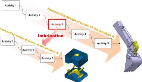
The second rule allows managing a specific design case: the design of a specific product may involve the design of others products. The most representative example concerns the manufacturing product. Indeed, to
be manufactured, a product requires tools which have to be designed as well. In this case, the initial product design process triggers the tool design process. Of course, this cascade effect can impact several sublevels (the tool has to be manufactured too). These provisional design processes can be similar or different. In
addition, this cascading effect (called
« imbrication » in Fig 4) contributes to modify the process homogeneity that is the reason why it is important to detect them. When an imbrication is identified, each process must be checked to verify if it consists of activities regarding only a single product. In other words, it is not possible to mix activities concerning several products in the same process.
Figure 3: Modification of the initial functional study process to satisfy the first « homogenization » rule. Functional specifications Create Calculate Represent Optimize Evaluate Validate Activity n Activity n-1 Créer Dimensionner Représenter Optimiser Evaluer Valider 1 Define the framework
2 Imagine 3 Choose
1 Define the framework 2 Describe 3 Distribute
1 Define the framework 2 Analyze 3 Décide 1 Test/Simulate 2 Recommend 1 Model 2 Allocate Représenter Modification Create Calculate Optimize Evaluate Validate A10 Create the structural schema of the product A11 Create functional geometry of each product component A12 Define the material linked to each product
component A13 Assembly product components Functional specifications Structural schema of the product Functional geometry of product components Functional geometry of the product Materials linked to the product components
CAD software Material definition software
Product bill of materials A10 Create the structural schema of the product A12 Create functional geometry of each product component A13 Define the material linked to each product
component A14 Assembly product components Functional specifications Structural schema of the product Functional geometry of product components Functional geometry of the product Materials linked to the product components
CAD software Material definition software
A11 Search technological
solutions
Technological solutions linked to the product
Office tools Product bill of materials Create Calculate Represent Evaluate Validate Create Calculate Represent Evaluate Validate Create Calculate Represent Evaluate Validate
Figure 4: « Imbrication » of provisional products design processes.
In the case study illustrated in Figure 5, there is an example of imbrication. Indeed, in the process called « manufacturing study » the activity A21 triggers the design of a second product (the roughing tools of the product basic components). An analysis of the process underlines that the activity A22 does not concern the first product, but the roughing tools. In compliance with this second rule, the activity A22 must disappear from the first provisional product design process (see Fig 5).
Finally, the third and last rule limits the
IDEF0 language framework. This limit
concerns about the number of data flows generated by an activity. So, a detailed activity can generate only one single data flow. This
limit allows being consistent with our detailed design activity definition (see Fig 2): a single design data flow, a single description data flow, a single validation data flow and each data flow can be generated by a single human resource. This rule is not applied to material resources (a data flow can be generated from several softwares). Without this rule, it becomes very difficult to identify and to manage project as well as product components.
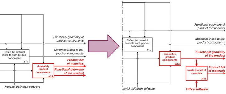
Concerning the case study, the
consequence of the application of this third rule is the creation of a new activity in the process called « functional study ». Indeed, the activity A13 generates two description data flows (see Fig 6).
Figure 5: Modification of the initial manufacturing study process to satisfy the second homogenization rule (imbrication).
Figure 6: New modification of the initial functional study process to satisfy the granularity rule.
Once this homogenization work is
performed (by the application of the three rules
explained previously), the processes
corresponding to both disciplines required in our case study take the form of IDEF0 diagrams as shown in Figure 7(a) and (b). To increase the readability of these diagrams, human resources and constraints are not displayed (such as rules and standards).
2.3 Application of collaboration rules [13] Through this third and last step, the method which aims to build a provisional
product design process integrates some
homogenized processes in a single process
adapted to collaborative work. This work is based on only two rules: an asynchronous
collaboration rule and a synchronous
collaboration rule.
The asynchronous collaboration rule : the asynchronous collaboration of a design process consist of all anteriority relations
linking the provisional design process
activities. It is therefore necessary to identify exhaustively all these links and control their
compatibility with material resources
associated to activities. We can notice that this last view ensure the consistency and the continuity of the « digital chain ».
Figure 7(a): Final processes resulting from the rules implementation (functional study).
A10 Create the structural schema of the product A11 Create functional geometry of each product component A12 Define the material linked to each product
component A13 Assembly product components Functional specifications Structural schema of the product Functional geometry of product components Product bill of materials
Materials linked to the product components
CAD software Material definition software
Functional geometry of the product
A14 create the bill of
materials
Figure 7(b): Final processes resulting from the rules implementation (manufacturing study).
Thus, in the case study, the application of this rule transforms the two homogenized processes into a single one. It is the first state of the future provisional product design process. During this work, three new activities appear: A11, A12 and A14 (Fig 8, Diagram B). A11 and A12 activities result from ambiguity and inconsistency coming from the initial activity « Create functional geometry of each product
component ». Indeed, this activity requires
knowing the exhaustive product bill of
material. But, at this stage of the project this latter cannot exist: indeed bills of material strongly depend on data created during the activity A11. To solve this problem, we propose an alternative solution:
Create product geometry equivalence
classes from the product structural kinematic scheme.
Create the geometry of the product
basic components from the product geometry equivalence classes.
Concerning the third and the last activity (called A14 in the Fig 8(b)), its sole role is to generate a piece of information needed to the
execution of the process called
“manufacturing”. Indeed, during the modeling of the only process “Design”, this activity was not necessary. This activity can be considered as an “asynchronous collaboration activity”.
The modified versions of the IDEF0 diagrams given in Figure 8 illustrate the result of this third step. The underlined items depict the changes on the processes called “design” and “manufacturing”. It is necessary to notice that the higher layer IDEF0 diagram given in Fig 8(a) is not needed: its role is only to underline relations linking processes “design” and “manufacturing”.
A21 Design the roughing tools for each product component
A22 Create the roughing
geometry of each product component
A26 Create the the final geometry of each product component
Final geometry of each product component
Roughing tools functional geometry of each product component
Roughing geometry of each product component
A20 Design the roughing manufacturing process
of each product component
A24 Design the finishing manufacturing process of each product component
Software to design manufacturing processes Functional surfaces Geometry of product basic components Functional geometry of product basic components A25 Design the finishing tools of each product component Finishing tools geometry of each product component Manufacturing specifications (finishing) A23 Characterize the material linked to the roughing of each
product component
A27 Characterize the material linked to the finishing step of each product component
Material definition software
Material linked to each product component Material characteristics answering
to functional requirements and allowing to manufacture the roughing
of each product component Manufacturing
specifications (roughing) Functional geometry of product basic components
Functional surfaces geometry of product basic components Materials characteristics linked to the product basic components
A28 Assembly product basic component in their final
definition Product final geometry CAD software + sizing software + simulation software Roughing manufacturing process of each product component
Finishing manufacturing process of each product component
Figure 8(a): Process resulting from the implementation of the asynchronous collaboration rule.
Figure 8(b): Process resulting from the implementation of the asynchronous collaboration rule.
Figure 8(c): Process resulting from the implementation of the asynchronous collaboration rule (level 1, manufacturing study).
A1 design a product (functional definition) A2 Design a product (manufacturing definition) Functional geometry of product basic components
Functional surfaces Geometry of product basic components Manufacturing specifications (roughing) Manufacturing specifications (finishing)
Functional geometry of product basic components
Material linked to each product component
Product final geometry
Office software Material definition software
Software to design manufacturing processes
Final geometry of each product component Product bill of materials
CAD software + sizing software + simulation software Functional
specifications
Materials characteristics linked to the product basic components
A10 Create the structural schema of the product A11 Create the functional geometry of kinematic equivalence classes
A13 characterize the material linked to each product
component
A14 Extract functional surfaces of each product
component A15 Assembly product components Functional specifications Structural schema of the product
Functional geometry of product Kinematic equivalence classes
Functional surfaces geometry of product basic components
Functional geometry of the product Materials characteristics linked
to the product components
CAD software Material definition software
A12 Create the geometry of
product basic components
Functional geometry of product basic components
A16 Create the bill of materials
Product bill of materials
Office software
A21 Design the roughing tools for each product component
A22 Create the roughing
geometry of each product component
A26 Create the the final geometry of each product component
Final geometry of each product component Roughing tools
functional geometry of each product component Roughing geometry of each product component
A20 Design the roughing manufacturing process
of each product component
A24 Design the finishing manufacturing process of each product component
Software to design manufacturing processes Functional surfaces Geometry of product basic components Functional geometry of product basic components A25 Design the finishing tools of each product component Finishing tools geometry of each product component Manufacturing specifications (finishing) A23 Characterize the material linked to the roughing of each
product component
A27 Characterize the material linked to the finishing step of each product component
Material definition software
Material linked to each product component Material characteristics answering
to functional requirements and allowing to manufacture the roughing
of each product component Manufacturing
specifications (roughing)
Functional geometry of product basic components
Functional surfaces geometry of product basic components
Materials characteristics linked to the product basic components
A28 Assembly product basic component in their final
definition Product final geometry CAD software + sizing software + simulation software Roughing manufacturing process of each product component
Finishing manufacturing process of each product component
To fully develop the asynchronous collaboration rule, the compatibility between data flows and material resources associated to activities have to be checked.
The synchronous collaboration rule: the synchronous collaboration is aimed at in performing occurrence of the same activity simultaneously. This is possible if, and only if, these occurrences are independent [14].
This rule deals with the concept of occurrences from the computer science domain. A provisional design process is not exactly composed of « activities », but more precisely it includes « activity classes ». Therefore the definition deals with « activity occurrence » in the synchronous collaboration rule. Indeed, during the product design, each activity can be repeated several times. For occurrences, if we consider a product made of three components, the activity « design product components » is realized three times. As illustrated in Figure 9, three occurrences of this activity are needed to design this product.
In the case study, the application of this rule leads to define for each design activity whether its occurrences are dependent or not. This analysis is done from processes shown in the figure 8(b) and (c). The result is summarized in the table 1.
Three activities (A11, A12, and A13) can be underlined because their occurrences are interdependent. Concerning A11 and A12, they
allow creating the geometry of product
equivalence classes and geometry of products basic components. All of these elements are
linked through interface area. So, it is
impossible to create them simultaneously
without referring them time and again causing time delay. In other words, anteriority between
activity occurrences is not well-defined.
Therefore, during planning of the product design, it will not be possible to create occurrences for these activities simultaneously. This disorganized work costs too much time and money. The same is true for the activity A13. Indeed, some links may exist between material characteristics associated to the class equivalence or elementary components which
make the corresponding occurrences
dependent.
From this observation, these three
activities are replaced with other independent occurrences of activities. In this case, it is possible to create planning maximizing parallel tasks. The result of this replacement leads us to propose the breaking down of each activity in a set of independent activities (see Fig 10).
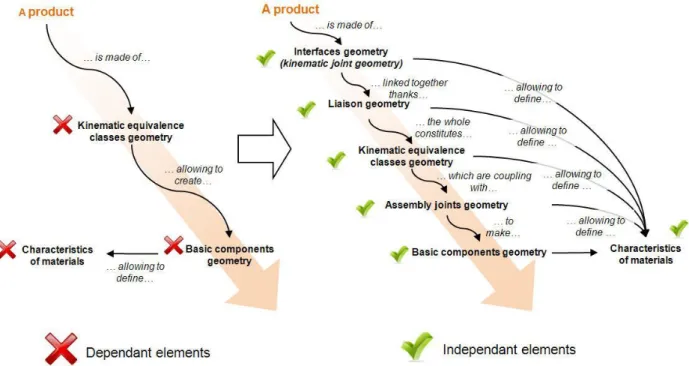
Figure 11 details this breaking down of the activity A12 [15] [16] [17] [18]. Thus, a geometry equivalence class is only made of two parts: interface geometry and link geometry. Both seem to be dependent. However, the first one is independent if created from its kinematic joints. Regarding the second one, it is also independent if it is created after the geometric interface.
Activities
A10 A11 A12 A13 A14 A15 A16 A20 A21 A22 A23 A24 A25 A26 A27 A28
Independent occurrence X X X X X X X X X X X X X
Dependent occurrence X X X
Table 1: Occurrence dependence/independence of each design activity.
Figure 10: example showing how to transform a dependent activity in an independent one.
Figure 11: Example illustrating the breaking down of the activity A12.
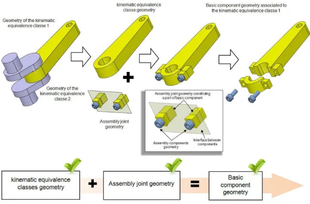
Concerning the activity A11, the method used is similar to activity A12. This time, the kinematic geometric equivalence class breaks down into two new and independent elements: the assembly joint geometry and the product basic components geometry. An assembly joint is composed of three items: basic fixing components, a joint surface to divide the kinematic equivalence class and additional geometry allowing the adaptation of each part
of the kinematic equivalence class to the technological solution of assembly (see Fig 12). From this proposition, the provisional design process take the form as depicted in Figure 13. This figure is an extract of the complete provisional design process. For the purpose of increase readability, only activities A10 to A18 are drawn. From the final provisional design process, two comments can be made.
Figure 12: Example illustrating the breaking down of the activity A13.
Figure 13: Final provisional product design process answering to the synchronous collaboration rule.
On one hand, this last version seems to be more complex than the previous one because it requires more activities. However, there is no relationship between the number of activities
constituting a process and the time required to achieve it. It is just a question of level of detail. Thus, a process composed of two complex activities will take as much time as a process
A10 Create the structural schema of the product A11 Create the kinematic joints of the product A12 create the functional geometry of kinematic equivalence classes A13 Create the assembly joints of the product Structural schema of the product
Kinematic joint geometry of the product A15 Create the geometry of product basic components Functional geometry of product basic components
Functional surfaces geometry of product basic components Materials characteristics linked to the product basic components Assembly joint geometry of the product Functional geometry of the product Office software
CAD software + simulation software Functional specifications
Kinematic equivalence classes geometry of the product
A14 Characterize the material linked to the functional definition of each product
component A16 Extract functional surfaces of each product component A17 Assembly product basic components in their functional definition
Material definition software
A18 Create the bill of materials
Product bill of materials
made of five basic activities. This fact is perfectly illustrated in the case study: new set of activities added to the initial design process come from the breaking down of the initial activity.
On the other hand, there is not a single solution meeting the synchronous collaboration constraint. Therefore, the solution proposed in this article is one of the several solutions. Furthermore, it could be interesting to compare several solutions in order to find the best one. The comparison can be made on the basis of
criteria such as number of independent
activities and level of complexity required to modify data. However, this comparison depends on contextual elements: essentially of the project design and the product it develops. Moreover, the different solutions need to be compared using the same case study.
3 The geometric modeling
process for mechanical
products designed in a
collaborative context
As explained in the first section of this article, the raison d’être of geometric modeling process is to design a product. So, the next step is to develop the geometric modeling process from the provisional product design process. To this end, activities have to be extracted from the design process using CAD software as materiel resource. Since the provisional product design process previously generated previously has been adapted to the collaboration work,
therefore the resulting geometric modeling
process is also adapted to it. At this step, it is important to remember that each geometric modeling activity requires design data in accordance with our definition of the « detailed design activity » (see Chapter 2.2). Moreover, each activity is associated with the specific
CAD software implementation procedure
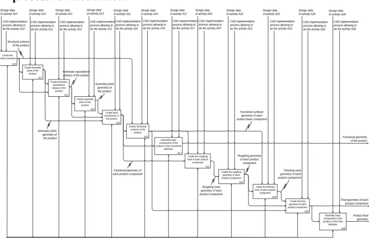
allowing its achievement (see Fig 14).
Figure 14: Geometric modeling process of mechanical product adapted to collaborative work. A10 Create the product structure A11 Create kinematic joints of the product A12 Create kinematic equivalence classes of the product A13 Create assembly joints of the product Structural schema of the product Kinematic joints geometry of the product A15 Create basic components of the product Functional geometry of each product component
Functional surfaces geometry of each product basic component Assembly joints geometry of the product Functional geometry of the product CAD software Kinematic equivalence classes of the product
A16 Extract functional surfaces of the product A17 Assembly basic components of the product in their functional
definition
A22 Create the roughing geometry of each product component
A26 Create the final geometry of each product component
Final geometry of each product component Roughing geometry
of each product component
A21 Create the roughing tools of each product component
A25 create the finishing tools of each product component
A28 Assembly basic components of the product in their final definition
Product final geometry CAD implementation
process allowing to do the activity A10
Design data of activity A10
CAD implementation process allowing to do the activity A11
Design data of activity A11
CAD implementation process allowing to do the activity A12
Design data of activity A12
CAD implementation process allowing to do the activity A12
Design data of activity A13
CAD implementation process allowing to do the activity A15
Design data of activity A15
CAD implementation process allowing to do the activity A16
Design data of activity A16
CAD implementation process allowing to do the activity A17
Design data of activity A17
CAD implementation process allowing to do the activity A20
Design data of activity A20
CAD implementation process allowing to do the activity A22 Design data of activity A22
CAD implementation process allowing to do the activity A25 Design data of activity A25
CAD implementation process allowing to do the activity A26 Design data of activity A26
CAD implementation process allowing to do the activity A28 Design data of activity A28 Finishing tools geometry of each product component Roughing tools geometry of each product component Design data of activity A10 Design data of activity A11 Design data of activity A12 Design data
of activity A13 Design dataof activity A15
Design data of activity A16 Design data of activity A17 Design data of activity A20 Design data of activity A10 Design data of activity A11 Design data of activity A12 Design data of activity A13 Design data of activity A15 Design data of activity A16
4 Example of result: the
implementation of the provisional
design process and its geometric
modeling process
To validate the provisional design and geometric modeling processes in an operational and collaborative context, the current study proposes the following two examples:
The compressor functional design.
The manufacturing of rod excavator
using data from functional design step. This component is manufactured by foundry and machining processes. These two examples have been developed
from our industrial experience, the
methodology validation has been performed several times with technicians in the frame of professional courses.
4.1 The compressor
This example is developed to verify and
validate the collaborative view of the
« functional design » aspect of the provisional product design process. Moreover, compliance with the geometric modeling process is also verified. The case study relies on CATIA V5 as a CAD software resource.
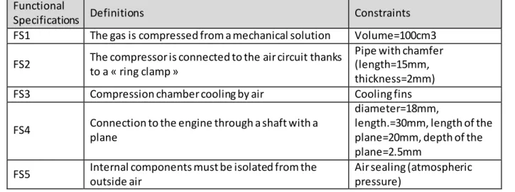
To start the design project, several functional specifications are defined first which are summarized in Table 2. Moreover, the project objective is to minimize the design time. For that, we have unlimited resources.
The product is firstly designed from the elements given in Table 2 by focusing only on the functional aspect of the product design.
Furthermore, the digital mock-up and
especially the geometric product models are created. These models are made of two main components: geometry and links. The first one is contained in a « part file » (its file extension in CATIA V5 is « .CATPart ») and the second one in an « assembly file » (its file extension in CATIA V5 is named « CATProduct »). To reproduce the network links defined in the
provisional product design process, two
different CAD functionalities fitted:
« Copy/Paste with link » to create the computer link and « Add or remove Boolean operations » to create a new geometry from the previous one. Because of this set of CAD tools, all the geometric data required to design the product
can be handled. Moreover, they are
characterized by a unique and personal identify. Thus, the combination of both computer links and identifier ensures the traceability of each
element from functional specifications to
product basic components.
In addition, the data quality is controlled by the procedure of the CAD software associated to each design activity. The results
are then reported in two representative
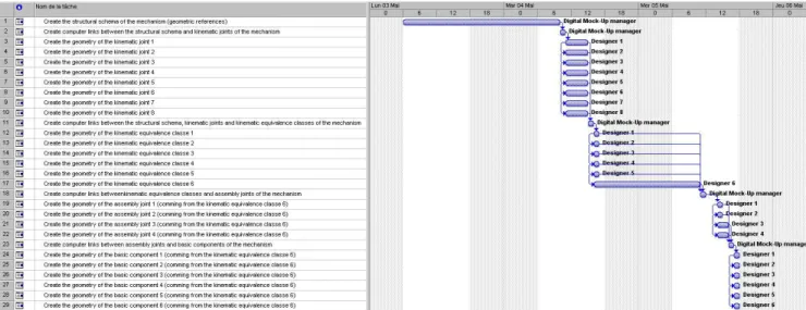
documents: the real project planning and the
geometric model structure. The project
planning (see Fig 15) shows how the design time is minimized through a set of tasks performed simultaneously. This result proves the potential of the proposed approach for project and data management.
Functional
Specifications Definitions Constraints
FS1 The gas is compressed from a mechanical solution Volume=100cm3
FS2 The compressor is connected to the air circuit thanks
to a « ring clamp »
Pipe with chamfer (length=15mm, thickness=2mm)
FS3 Compression chamber cooling by air Cooling fins
FS4 Connection to the engine through a shaft with a
plane
diameter=18mm,
length.=30mm, length of the plane=20mm, depth of the plane=2.5mm
FS5 Internal components must be isolated from the
outside air
Air sealing (atmospheric pressure)
Figure 15: Real planning of the compressor design.
Based on the analysis of the Figure 16 (we just focus on links displayed), the geometric model structure is in perfect adequacy with the
links network previously identified among
design activities. In general, computer links given in this document prove the high level of complexity of digital mock-up data and the importance to control them especially during modification steps. Indeed, propagation of
changes is a key functionality in the update of product design data. In the compressor example, thanks to our provisional product design process, this control is naturally implied. Each change follows the same two steps process: identify the data to change, then
identify and update its filiation through
computer data links.
It is important to notice that the product (or more specifically its bill of materials) is not created in a single step. It appears gradually as the provisional design process progresses (in Fig 16, see all computer links going to the design activity « A17 »). This evolutionary characteristic is very important, because it
avoids creating useless product basic
components. Thus, in current case study each element is designed only if its existence can be justified. So, the adequacy between the product and the customer requirements is increased while costly and unpredictable changes are reduced. Figure 17 details more precisely two
activities sequences: « A11/A12 » and
« A12/A13/A15 ». The first one shows the transition from kinematic joints to kinematic equivalence classes. The second one focuses on the transition from assembly links to product
basic components. These two examples
underline that the provisional product design process can be implemented irrespective of the CAD software used.
4.2 The excavator rod
In the second example, the main objective is to validate the continuity between the « functional design » and the « manufacturing study ». The Figure 18 illustrates this point through a specific component: an excavator rod. The result of the main design activities
(functional definition, roughing tools
definition, roughing definition and final
definition) [19] are illustrated. The
manufacturing processes used are the foundry
(roughing definition) and machining (final
definition).
Moreover these figures show that data from « functional design » are used during the
« manufacturing process ». Again, links
required in the provisional product design process are fully created in the geometric model (and in general in the digital mock-up). So, tools available in CAD software can be easily used to implement this second part of the geometric modeling process.
Figure 17: Details of occurrences coming from geometric modeling process activities A11 (left), A12 (middle) and A13 (right)
Figure 18: Illustration of geometric modeling process activities A21, A22 et A26.
5 Conclusion
In this article, a geometric modeling process for mechanical products is presented. This process is both generic and suited to collaborative and interactive work. The result is obtained using a methodology which does not refer to a specific product (to keep a high genericity level), but it takes into account the way used to design a product keeping the best integration of collaboration and interactivity. It is based on several elements:
the control of coordination through the
identification and the management of anteriority constraints between design activities,
the identification of flexibility area in
the design schedule to implement
concurrent engineering,
To give the relevant information at the
good moment to the different experts involved in the product design.
For this purpose, several processes were formalized and modeled. However, this work is not enough since a design process requires many collaborations and it is essential to check their compatibility with data management and project goals (mainly cost and delay). Meeting this requirement leads to modify the initial
design know-how. In our methodology, this is controlled through a set of generic rules
(homogenization rules, asynchronous
collaboration rule and synchronous
collaboration rule).
Finally, a « provisional product design process » is obtained from the application of these three major rules. It is made of design activities using several resources (human or hardware). The geometric modeling process proposed in this paper is composed of design activities using CAD software as material resource. As it comes from the provisional design process, it inherits its collaborative properties.
The proposed methodology leads us to make three concluding remarks:
The approach adopted in the proposed
methodology is original to solve the project and data management problem. Indeed, the other studies on this domain
develop the capitalization and the
exploitation of data and knowledge [20].
It is not a deterministic methodology. It
is only a tool that helps a project manager to prepare his design project. So, the final result depends on the
solutions he proposes during the
methodology implementation. Indeed,
this work is a true creativity work from
where some original solutions can
emerge.
Integration of collaborative aspects
makes it long and complex to
implement. Nevertheless, this time
investment is quickly compensated for
the high genericity level of the
provisional design process. So, the same provisional design process can be used for many different products.
Concerning the resulting geometric
modeling process, we will make several remarks can be performed too.
It meets all product geometric modeling
requirements ensuring the CAD digital chain consistency.
It does not require creating new CAD
tools (for example, it works with CATIA V5 standard tools).
It contributes to structural digital
mock-up data easing their manipulation during modification phases.
It distinguishes creativity steps from
data creation steps (the both activities does not require the same skills).
It allows defining some accurate and
durable CAD proceedings and CAD skills. The both are very important to build the better team corresponding to a specific design project.
The next steps of this works are:
To test the methodology on more
complex products such as mechatronic products over their life cycles (which include integrating the recycling aspect in the design process)
To develop a specific tool on the basis
of this methodology in order to manage
design projects. This will reduce
designers and the project manager workload concerning data management.
6 References
[1] DELPHI Automotive Systems, «
Delphi met à plat ses arborescences », CADReport n°192, février 2004.
[2] S. TICHKIEWITCH, P. VERON «
Methodology and product model for
integrated design using multi-view
system », Anal of the CIRP, Vol. 46/1, 1997.
[3] D. SCARAVETTI, « Formalisation
préalable d’un problème de conception pour l’aide à la décision en conception préliminaire », Laboratoire TREFLE, 2004 (thèse).
[4] A. BERNARD, M. LABROUSSE, N.
PERRY, « LC universal model for the
enterprise information system
structure » in « Innovation in Life
Cycle Engineering and Sustainable
Development », publisher Springer
Netherlands, ISBN: 978-1-4020-4601-8, pp 429-446, 2006
[5] O. POVEDA, D BRISSAUD, O
GARRO, « A tool for the design process technical control » in « Recent Advances in Integrated Design and
Manufacturing in Mechanical
Engineering », publisher Springer
Netherlands, ISBN: 978-90-481-6236-9, chapter 3 pp 483-492, 2003.
[6] E. VAREILLES, T. COUDERT, M
ALDANONDO, L. GENESTE, J. ABEILLE, « Coupling system design and project planning: Discussion on a bijective link between system and
project structures », 14th IFAC
Symposium on Information Control
Problems in Manufacturing,
INCOM'12, 2012.
[7] F. DEMOLY, D. MONTICOLO, B.
EYNARD, L. RIVEST, S. GOMEZ,
« Multiple viewpoint modeling
framework enabling integrated
product–process design », IJIDEM,
Volume 4, Issue 4, pp 269-280.
[8] M. BORDEGONI, F. FERRISE, M.
AMBROGIO, F. CARUSO, F.
BRUNO, « Data exchange and multi-layered architecture for a collaborative
design process in virtual
environments », IJIDEM, Volume 4, Issue 2, pp 137-148.
[9] G. DRIEUX, J-C. LEON, F.
GUILLAUME, N. CHEVASSUS, L.
FINE, A. POULAT, « Interfacing
representation. Part 2: Model
processing description », IJIDEM,
Volume 1, Issue 2, pp 67-83.
[10] M.McCLELLAN, « Collaborative
manufacturing », ISBN 1-57444-341-0, Editions St Lucie Press, 2003
[11] G. DOUMEINGTS, « Decisional
modeling using the GRAI grid »,
Handbook on Architectures of
Information System, 1998 (Springer-Verlag), pp. 313-338.
[12] A. BERNARD, N. PERRY, «
Fundamental concepts of
product/technology/process
informational integration for process modeling and process planning »,
International Journal of Computer
Integrated Manufacturing, Volume 16,
Numbers 7-8, October-December
2003, pp. 557-565.
[13] I. SALAU, O. GARRO, P. MARTIN,
« Distributed Design Theory and
Methodology in the Context of
Concurrent Engineering », Concurrent
Engineering: Research and
Application, Paul and Sobolewski, ISSN 1076-2868, Vol. 3 N°1, pp. 323-331, 1995.
[14] N. SUH, « The principles of design »,
Oxford Series, 1990.
[15] C. MASCLET, « Vers une assistance à
la synthèse de dispositifs
technologiques assurant une Liaison Mécanique », laboratoire LGMD de Toulouse, le 30 mars 1992 (thèse).
[16] J-P. PERNOT, B. FALCIDIENO, S.
GUILLET, J.-C. LEON, F.
GIANNINI, « Aesthetic design of
shapes using fully free form
deformation features », Int. J. of Engineering Design, Vol. 16, n°2, 2005, pp 115-133.
[17] A. ALOUI, JC.BOEHM, « Définition
d'architectures organiques de systèmes
techniques : proposition d'une
méthodologie », Traité Management et Gestion des STIC (éd. Hermès), chap. 5, pp. 103-141.
[18] S. MER, A. JEANTET, S.
TISCHKIEWITCH, « Les objets
intermédiaires de la conception,
modélisation et coordination », Le
communicationnel pour concevoir
(Euripia, Paris, 1995), pp. 21-42.
[19] O. HAMRI, J-C. LEON, F.
GIANNINI, B. FALCIDIENO, A.
POULAT, L. FINE, «Interfacing
product views through a mixed shape
representation ». Part 1: Data
structures and operators, Int. J. on Interactive Design and Manufacturing, Vol. 2, Springer Verlag, 2008.
[20] A. BERNARD, K.RAMANI, R D .
SRIRAM, S. CHANDRASEGARAN,
« The evolution, challenges, and future of
knowledge representation in product
design systems » in « Computer Aided Design », Volume 45, Issue 2, Pages 204–228, 2013.

![Figure 11 details this breaking down of the activity A12 [15] [16] [17] [18]](https://thumb-eu.123doks.com/thumbv2/123doknet/7396546.216991/10.893.95.703.727.1091/figure-details-breaking-activity-a.webp)