Délivré par l’Université Toulouse 3 – Paul Sabatier
Mateusz SZCZEPANSKI
Development of methods allowing the test and the
comparison of low-voltage motors insulation systems
running under partial discharges (fed by inverter)
École doctorale : GEET - Génie Electrique Electronique et Télécommunications __________________du système au nanosystèmeSpécialité : Génie Electrique Unité de recherche :
LAPLACE - Laboratoire PLAsma et Conversion d'Énergie - CNRS-UPS-INPT Thèse dirigée par
David MALEC et Pascal MAUSSION Jury
M. Ian COTTON Professor at The University of Manchester, UK Rapporteur M. Farid MEIBODY-TABAR Professor at Université de Lorraine, France Rapporteur M. Thierry LEBEY Director of research at CNRS – LAPLACE, France Examinateur Mme Sonia AIT-AMAR Associate Professor at Université d’Artois, France Examinateur M. Mats ALAKÜLA Professor at Lund University, Sweden Examinateur M. David MALEC Professor at Université Paul Sabatier, France Directeur M. Pascal MAUSSION Professor at INP de Toulouse, France Co-directeur Mme. Anne GIMENEZ Laboratory Manager at Nidec Leroy-Somer, France Invitée
M. Philippe MANFÉ Technical Director at Nidec Leroy-Somer, France Invité
ABSTRACT
Title: Development of methods allowing the test and the comparison of
low-voltage motors insulation systems running under partial discharges (fed by inverter).
Key words: partial discharges, electrical insulation system, low-voltage motor, inverter,
PWM, design of experiments.
Since the development of power electronic components, which allowed the manufacturing of reliable and efficient inverters, variable speed drives using inductive motors have become more and more popular. The PWM technique has proven to be a very effective method of rotational speed control. However, the fast changing voltage pulses, with very steep slopes (in the order of a few kV/μs), has brought new hazards for the electrical insulation system of such motors. Very high frequency harmonic components of PWM voltage will result in significant overvoltage due to an impedance mismatch between the cable and the motor. As an effect, the voltage seen by some parts of the insulation system may exceed the Partial Discharge Inception Voltage (PDIV) stating localized partial discharges activity.
The insulation system in low-voltage machines (called type I) is based almost entirely on polymer materials, which are not able to support partial discharge activity throughout their lives. Due to the use of frequency inverters especially the primary insulation of the magnet wire is endangered in comparison with system-powered machines. As a result this is often the weakest link of the insulation system leading to a premature breakdown of the machine.
The aim of this thesis is to investigate and analyze the aging process of the enameled wire exposed to different factors and to propose a method allowing to predict their lifespans in given conditions. This study introduces a prediction based on the Design of Experiments method and the statistical Weibull distribution. Thanks to the model obtained with short multi-stress (temperature, voltage, frequency) aging tests, it is possible to predict the results of significantly longer ones. Moreover, the adapted methodology is proposed that allows to predict the scatter of the long tests basing on the short-time results dispersion. The predictions are compared with the experimental data in order to prove the model accuracy.
RESUME
Titre: Mise au point de méthodes permettant le test et la comparaison de
systèmes d’isolation des moteurs basse tension fonctionnant en régime de décharges partielles (alimentation par onduleur).
Mots clé: décharges partielles, système d’isolation électrique, moteur basse tension,
onduleur, MLI, plan d’expériences
Depuis le développement des composants d’électronique de puissance qui ont permis la fabrication d'onduleurs fiables et efficaces, les entraînements à vitesse variable utilisant des moteurs asynchrones sont devenus de plus en plus populaires. La technique MLI s'est avérée être une méthode très efficace de contrôle de la vitesse de rotation. Cependant, les impulsions de tension, avec des pentes très raides (de l'ordre de quelques kV/μs), ont apporté de nouveaux risques pour le système d'isolation électrique des moteurs. La richesse harmonique de la tension MLI entraînera une surtension significative due à une différence d'impédance entre le câble et le moteur. En effet, la tension observée par certaines parties du système d'isolation peut dépasser la tension d'apparition des décharges partielles (ang. PDIV); ce qui amorcera une activité de décharges partielles localisée.
Le système d'isolation des machines basse tension (appelé type I) est basé presque entièrement sur des matériaux polymères qui ne sont pas conçus pour supporter des décharges partielles tout au long de leur vie. En raison de l'utilisation de variateurs de fréquence, l'isolation primaire du fil émaillée est en danger par rapport aux machines alimentées par réseau. En conséquence, c'est souvent le point le plus faible du système d'isolation qui conduira à la panne prématurée d'une machine.
Le but de cette thèse est d'étudier et d'analyser le processus de vieillissement du fil émaillé exposé aux différents facteurs et de proposer une méthode permettant de prédire les durées de vie dans des conditions fixées. Cette étude introduit une prédiction basée sur la méthode des plans d'expériences et la distribution statistique de Weibull. Grâce au modèle obtenu avec des tests de vieillissement courts multicontraintes (température, tension, fréquence) il est possible de prédire les résultats de tests significativement plus longs. De plus, la méthodologie proposée permet de prédire la dispersion des essais longs en se basant sur la dispersion des résultats à court terme. Les
prédictions sont comparées avec les données expérimentales afin de prouver la précision du modèle.
TABLE OF CONTENT
Abstract ... 1
Résumé ... 3
Table of content ... 5
General introduction ... 9
1. CHAPTER 1: State of the art ... 17
1.1. Introduction ... 17
1.2. General information ... 18
1.2.1. Electric machines ... 18
1.2.2. Electrical insulating materials ... 24
1.3. Electrical insulation system of low voltage motors ... 34
1.3.1. Phase-to-ground insulation... 36
1.3.2. Phase-to-phase insulation ... 36
1.3.3. Turn-to-turn insulation ... 36
1.3.4. Impregnating varnish or resin ... 40
1.4. Partial discharges ... 42
1.4.1. Discharge mechanism ... 43
1.4.2. Paschen’s law ... 47
1.4.3. Partial discharge inception voltage (PDIV) ... 49
1.5. Inverter fed machines ... 51
1.5.1. Variable-speed drive ... 51
1.5.2. Partial discharges in inverter-fed machines ... 54
1.6. Conclusion... 60
2. CHAPTER 2: Accelerated aging tests on insulating materials ... 67
2.1. Introduction ... 67
2.2. Introduction to accelerated aging tests ... 68
2.2.2. Aging factors and stress types ... 70
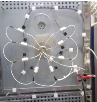
2.3. Accelerated aging test bench ... 73
2.3.1. General information and requirements for accelerated aging test bench ... 73
2.3.2. Components and their roles ... 74
2.3.3. Measurement automation ... 77
2.4. Partial discharges measurements ... 80
2.4.1. On-line and off-line PD measurements ... 80
2.4.2. Overview of partial discharges detection methods ... 80
2.4.3. PDIV measurements on twisted pairs ... 82
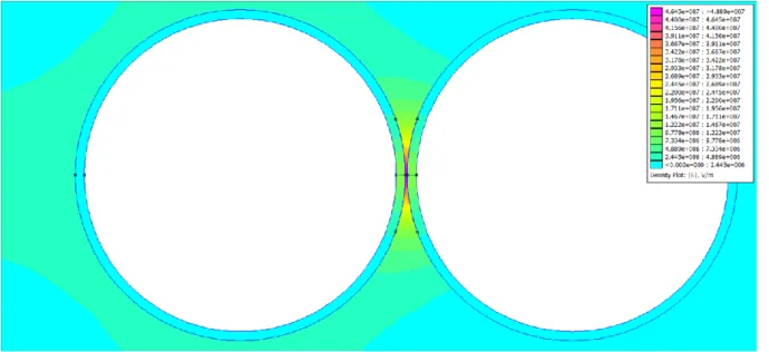
2.4.4. Determination of the PDIV of a twisted pair using finite element method simulation ... 85
2.4.5. PDIV measurements on a low-voltage motor... 87
2.4.6. Partial discharges measurements as a method for winding fault detection ... 93
2.4.7. Discussion over the test parameters in pulse mode ... 95
2.5. Life data analysis ... 100
2.5.1. Lifetime distributions ... 100
2.5.2. Censoring ... 103
2.5.3. Weibull statistical distribution ... 104
2.6. Conclusion ... 112
3. CHAPTER 3: Factors influencing the lifespan of insulating materials .. 117
3.1. Sample choice for accelerated aging tests ... 117
3.1.1. General requirements ... 117
3.1.2. Overview of existing samples of insulation system ... 119
3.2. Influence of temperature on the lifespan of insulating materials ... 126
3.2.3. Local overheating due to a partial discharges activity ... 131
3.3. Influence of powering parameters on the lifespan of insulating materials ... 134
3.3.1. Voltage amplitude ... 134
3.3.2. Frequency ... 135
3.4. Influence of environmental factors on the lifespan of insulating materials ... 137
3.4.1. Ozone concentration... 137
3.4.2. Humidity ... 142
3.5. Influence of the surface state on the lifespan of insulating materials . 144 3.5.1. Influence of wire surface contamination ... 144
3.5.2. Protocol of samples preparation ... 146
3.6. Conclusions ... 147
4. CHAPTER 4: Lifespan modeling ... 153
4.1. Introduction ... 153
4.2. Overview of existing lifespan models ... 154
4.2.1. Single factor models ... 154
4.2.2. Two factors models ... 155
4.2.3. Summary ... 157
4.3. Design of experiments ... 159
4.3.1. Definition and general information ... 159
4.3.2. Model construction – theoretical introduction ... 159
4.3.3. 2- and 3-factors short time lifespan models ... 163
4.4. Lifespan prediction ... 171
4.4.1. Model extrapolation ... 171
4.4.2. Prediction of results scatter ... 175
4.4.3. Experimental verification ... 177
4.5.1. Comparison of the short-time model coefficients ... 182
4.5.2. Scatter prediction ... 185
4.5.3. Extrapolation towards long-time results ... 186
4.6. Conclusion ... 190
General conclusion and perspectives ... 191
References ... 195
List of figures ... 207
GENERAL INTRODUCTION
The electric insulation system (EIS) consist of all the insulating materials altogether allowing the correct functioning of electric machine. Although it is not directly influencing the machine’s efficiency, its design is crucial. For years, it has been optimized in order to reduce its costs and increase its performance. The insulation electrical systems can be divided into 2 main categories. Type I is generally used in low-voltage machines as it is based almost entirely on polymer materials. Type II uses more robust inorganic materials, but due to its significantly higher cost, it is reserved almost uniquely for high voltage machines (>700 VRMS).
The development of power electronic components allowed the manufacturing of reliable and efficient inverters. As a result, variable speed drives using inductive motors have become more and more popular. They use mostly PWM technique, which has proven to be a very effective method for rotational speed control. Nevertheless, the fast changing voltage pulses generated in PWM, with very high dV/dt (in the order of a few kV/μs), has brought new hazards for the electrical insulation system. New components based on wide band gap semiconductors, such as SiC or GaN, will on one the hand enable to limit the commutation losses in the inverter, but on the other hand will even further increase the dV/dt. Very high frequency harmonic components of the PWM voltage will result in significant overvoltage due to an impedance mismatch between the cable and the motor. As an effect, the voltage seen by some parts of the insulation systems can be significantly higher than the rated value. This is particularly the case for turn-to-turn voltage in random wound machines (majority of low voltage machines). If high enough, the voltage can exceed the Partial Discharge Inception Voltage (PDIV), leading to a localized partial discharges activity in the machine. Partial discharges (PDs) are electrical discharges that partially circuit the insulation. Although the short-circuit is just partial and does not immediately lead to the machine’s failure, the PDs induce a phenomenon of erosion due to the bombardment of charged particles, chemical deterioration and local thermal stress. Type II insulation system is designed to withstand the PDs during his lifespan. However type I, i.e.: low-voltage insulation system, can be quickly degraded by PDs, leading inevitably to machine’s premature breakdown. The defects in the insulation system are, beside the problems with bearings, one of the most common causes of machines breakdown. Due to the use of frequency inverters,
especially both primary and secondary insulations of the magnet wires are endangered in comparison with system-powered machines. If all the winding is not correctly impregnated by the varnish (secondary insulation), the weakest part of the insulation system will be the primary insulation (enamel).
The aim of this thesis is to investigate and analyze the aging process of enameled wires exposed to different aging factors and to propose a method allowing to predict their lifespans in given conditions. The main aging factors studied in this work are voltage amplitude, switching frequency and temperature. However, the influence of other secondary factors, such as ozone concentration, has also been studied. This work introduces a lifespan prediction based on the Design of Experiments (DoE) method and the Weibull distribution. This methodology is very flexible, which means that it is not limited by the number or nature of aging factors as well as it automatically includes the interactions between factors. Thanks to the model obtained with short multi-stress accelerated aging tests in the order of few hours, it is possible to predict the results of significantly longer ones. Moreover, an original adapted methodology is proposed that allows to predict the scatter of the long tests based only on the short-time results dispersion. The predictions are compared with the experimental data and show a good correlation, even for lifespans 100 times longer than short-time test points. Finally, we have shown that the same technique can be used as a quick and reliable comparison method between samples of different insulating materials.
This thesis is the result of a collaboration between the Laboratory on Plasma and Conversion of Energy (LAPLACE) in Toulouse and Leroy-Somer (part of Nidec group) in the framework of a CIFRE thesis. The works in LAPLACE laboratory were conducted in collaboration between the two research teams: Dielectrics Materials in the Energy Conversion (MDCE) and Control and Diagnostic of Electrical Systems (CODIASE). This cooperation gave to the company the scientific support for manufacturing better quality products, while the laboratory could profit from technical experience of Leroy-Somer.
This PhD dissertation is divided into four chapters. A brief description of the content of those chapters is given below.
Chapter I: Partial discharges in low voltage machines
This chapter explains in detail how partial discharges can appear in low voltage machines. First it gives some basic information concerning electric machines and some insulating materials, typically used in those machines, as well as some key parameters used to characterize those materials. It is followed by a detailed description of electrical insulation system. In the next subchapter the information concerning the physics of partial discharges are given. Finally, the chapter is concluded by the problem of partial discharges in inverter-fed machines.
Chapter II: Accelerated aging tests on insulating materials
This chapter gives general information about accelerated aging tests through a comprehensive literature review. After some general introduction concerning the types of such tests, it describes the test bench constructed for the purpose of those tests. In this chapter also partial discharges measurements are discussed in details, as a PD activity is the key factor determining the aging mechanism in this study. Finally, the chapter covers life data analysis, especially Weibull’s distribution.
Chapter III: Factors influencing the lifespan of insulating materials
Chapter III describes the factors influencing the lifespan of insulating materials in electrical machines. First, the choice of a typical sample for accelerated aging tests is discussed. Other subchapters describe the influence of temperature, voltage amplitude and frequency on the lifespan. Lastly, the influence of environmental factors, such as ozone concentration, and surface state are discussed. All those preliminary tests enabled the correct lifespan model construction, as presented in the last chapter.
Chapter IV: Lifespan modeling
The last chapter focuses on the lifespan modeling using the design of experiments (DoE) method. Firstly, it presents the brief overview of different techniques of lifespan modeling. Then, it gives a detailed theoretical description of the DoE method, followed by the construction of 2- and 3-factors lifespan models. Next, the technique used for lifespan prediction with scatter prediction is explained. Finally,
the model is confronted with experimental results for the lifespans up to 100 times longer than the ones of the model tests. Lastly, the chapter shows how this approach can be applied as a comparison method, providing a quick while reliable rank of original solutions.
Finally, a conclusion of this work is presented as well as future works are proposed.
CHAPTER 1
Table of content
1. CHAPTER 1: State of the art ... 17
1.1. Introduction ... 17 1.2. General information ... 18 1.2.1. Electric machines ... 18 1.2.1.1. Asynchronous machines ... 18 1.2.1.2. Random-wound machines ... 19 1.2.1.3. Manufacturing process ... 20
1.2.2. Electrical insulating materials ... 24
1.2.2.1. Typically used materials ... 25
1.2.2.1.1. Organic polymer materials ... 25
1.2.2.1.2. Inorganic materials ... 26
1.2.2.2. Characteristic parameters ... 26
1.2.2.2.1. Relative permittivity ... 27
1.2.2.2.2. Dielectric dissipation factor... 28
1.2.2.2.3. Thermal class ... 30
1.2.2.2.4. Breakdown strength ... 33
1.3. Electrical insulation system of low voltage motors ... 34
1.3.1. Phase-to-ground insulation... 36
1.3.2. Phase-to-phase insulation ... 36
1.3.3. Turn-to-turn insulation ... 36
1.3.3.1. Magnet wire manufacturing process ... 38
1.3.3.2. Enamel materials ... 39
1.3.3.2.1. Conventional wires ... 39
1.3.4. Impregnating varnish or resin ... 40 1.4. Partial discharges ... 42 1.4.1. Discharge mechanism ... 43 1.4.1.1. Townsend mechanism... 43 1.4.1.2. Streamer mechanism ... 46 1.4.2. Paschen’s law ... 47
1.4.3. Partial discharge inception voltage (PDIV) ... 49
1.5. Inverter fed machines ... 51
1.5.1. Variable-speed drive ... 51
1.5.1.1. The principle of frequency converter... 51
1.5.1.2. IGBT ... 52
1.5.1.3. Pulse width modulation (PWM) ... 53
1.5.2. Partial discharges in inverter-fed machines ... 54
1.5.2.1. Theory of transmission line ... 54
1.5.2.2. Voltage reflection and overvoltage at machine terminals ... 55
1.5.2.3. Influence of both cable length and voltage rise time ... 57
1.5.2.4. Turn-to-turn voltage in inverter-fed motors... 58
1. CHAPTER 1: STATE OF THE ART
1.1. Introduction
This aim of this chapter is to present to the reader the context of this thesis. The first part presents a brief description of AC machine stators, concerning mostly on the parameters that can influence the lifespan of a final product. This part gives also some information concerning the materials typically used in low-voltage machines as well as their characteristics.
The second part describes in details the electrical insulation system of low voltage AC machine stators. It gives examples of all the insulating materials as well as their properties in order to better understand how they can influence the lifespan of the insulation system of such machines.
The third part explains the phenomenon of partial discharges, describing in details its physical principles. It introduces as well the terminology used later throughout the whole thesis.
The last part of this chapter is dedicated to inverter fed machines. It shows how the different parameters of drive and cable can influence the voltage amplitude at the motors terminals. Higher electrical stress seen by the electrical insulation of inverter fed machines may lead to their premature failure.
1.2. General information
1.2.1. Electric machines
Electric machine is defined as an energy transducer that can transform electric energy into mechanical energy (electric motor) or vice versa (generator). Depending on the waveform of the power supply, machines can be divided into 2 categories: direct current (DC) machines and alternative current (AC) machines.
The DC machines are very versatile. Different combinations of field windings (separate excitation, shunt, series or compound) results in a wide variety of final characteristics while assuring the relative simplicity. Thanks to the ease of control, DC machines have been frequently used in application requiring a wide range of rotating speeds or precise control of motor output. Unfortunately, these machines are quite expensive, taking into consideration both high initial cost as well as increased maintenance and operation costs due to the presence of commutator and brush gear. So-called “brushless DC machines”, using permanents magnets to create excitation field, although allow to eliminate the problematical commutator, are often too expensive due to elevated price of the magnets. Since the development of power electronics, the technology of AC drive systems has flourished. As a result these system replace DC machines in applications previously associated almost exclusively with the latter, for instance in robots and railway application [1] [2].
The AC machines can be subdivided into 2 categories: synchronous and asynchronous (also called inductive). For the former, the rotating speed is directly proportional to the frequency of the stator voltages. This is not the case for the latter ones – asynchronous machines (see 1.2.1.1). In synchronous machines in most cases (except for e.g. reluctance machines, which will not be discussed in this work) currents in rotor windings are supplied through a rotating contact from the stationary frame by means of carbon brushes, which contact rotating corrector or slip ring. On the contrary, in asynchronous machines these currents are inducted by the motion of the rotor in the rotating magnetic field created by the alternating currents in stator windings.
1.2.1.1. Asynchronous machines
the one on the stator. In order to make rotor terminals accessible, insulated slip rings mounted on the shaft and carbon brushes bearing are used. These machines, due to quite complicated construction and thus higher price and maintenance cost, are relatively rarely used, only in a limited number of specialized applications.
On the contrary, squirrel-cage rotor machines, where the rotor winding consists of metal bars embedded in the slots and short-circuited at each end, have much simpler construction and thus are cheap, very rugged and require minimal maintenance costs. Thanks to all those advantages these machines are by far the most commonly used type of motor, available in wide range of sizes and powers [3] [2].
1.2.1.2. Random-wound machines
The windings of the machines can be divided into two groups: form-wound or random-wound [4].
Form windings use rectangular or square magnet wires. The position of each individual turn inside the slot is well controlled. As a result a turn-to-turn voltage stress as well as temperature distribution is more uniform compared to random-wound machines. Also the end windings are shaped to optimize the material consumption, promote cooling or reduce coil contamination by allowing better air circulation. The coils are very rigid with almost no possibility of movement thus limiting the probability of mechanical damages. Due to much higher cost, both of materials and labor, this type of winding is used almost only for high voltage or high power (typically more than hundreds of kW) low voltage machines.
Figure 1.1. Form winding: scheme of the slot (left) and picture of end winding (right) [4].
Low voltage and/or low power machines are almost exclusively random-wound. The windings are made with insulated round copper conductors, called magnet wire. As their arrangement in the coil during skeining or insertion cannot be controlled, the winding is called random. As a result wires from one turn can touch any other turn and therefore the maximum turn-to-turn voltage can be significantly higher than for form-wound machines. In the worst-case scenario the beginning and the end of the winding can be adjacent. According to some studies [5] the probability of such a situation can be higher than 90%. Moreover, this type of winding is much more vulnerable to mechanical damages due to vibrations or loose wire. Further problems can be caused by uneven resin build-up, non-uniform temperature distribution or higher accumulation of moisture and contaminates due to unsteady air circulation.
Figure 1.2. Random winding: scheme of the slot (left) and picture of end winding (right) [4].
1.2.1.3. Manufacturing process
Machine manufacturing is a complex, multistage process. It varies significantly depending on the type of the machine, its size, rated power and voltage and many other factors. The processes range from unitary production, manual or semi-automated, of special machines to fully automated massive production of most popular models. This section concentrates mostly on stator manufacturing process of low-voltage machines, as it can strongly influence the final properties of the electrical insulation system.
Stator magnetic core is made with laminated steel sheets welded together. The lamination allows to significantly limit the eddy currents induced in the core thus keeping related losses to the minimum [6].
The winding of the stator starts with lining each slot of the machine with a slot liner providing phase-to-ground insulation (see section 1.3.1). This stage can be done manually or automatically. Some grease can be added so that the slot liner can be smoothly inserted or to facilitate the coils insertion [6].
Figure 1.3. Stator core with slot liners in each slot [7]
The next step consists in the preparation of the coils. As most of the low voltage motors are random-wound (see section 1.2.1.2), the winding is made with round copper magnet wire. In semi-automated winding systems, the coils are first spooled, manually or automatically, on the coil former. Then the coils are inserted inside the slots manually. In fully automated winding systems the coils are spooled on the special forks. The magnet wire can be lubricated to assure smooth coil insertion. Once all coils are spooled they are simultaneously pulled inside the stator slots. If the winding design requires the coils of 2 different phases inside the same slot, the slot separators are added in-between the coils prior to insertion in order to provide the phase-to-phase insulation (see section 1.3.2) [6].
Once the winding is finished, each slot is closed with a wedge separator. At end winding, different phases are separated with phase separators (see section 1.3.2) and coil outhangs are reshaped and immobilized using tie cords. At this stage the leads, in adapted sleeving, are connected and all other insulation reinforcements are added (see Figure 1.10).
The next step is an impregnation. There are three major techniques of impregnation depending upon the type and size of winding or production rate.
First, called dip impregnation, it consists in slowly dipping the preheated winding inside the varnish tank. After a certain time, the winding is removed to allow the excess varnish to drip. Afterwards, the varnish is cured, usually in a continuous
furnace. In a slight variation of this simple process, called flood impregnation, the pre-dried winding is kept in a tank. The varnish is slowly pumped until the winding is completely submerged. This method is cheap and best adapted to mass production. Unfortunately, the varnish does not always penetrates properly inside the slot, due to high fill factor, as well as it can accumulate on unwanted parts of the winding [8] [9] [10].
Figure 1.4. Dip impregnation of a stator winding [8]
In order to better control the impregnation process the Vacuum-Pressure Impregnation (VPI) method was developed. First, the winding placed in a chamber is subjected to low vacuum. The varnish is fed in until the winding is completely submerged. Then, to provide better penetration of varnish, dry compressed air or pressurized nitrogen is applied. In comparison to dip impregnation this method is far more expensive and time-consuming, thus is not commonly used for the low-voltage machines [8] [9] [6] [10].
The last technique, used mostly for smaller machines, is trickle impregnation. In this method, the resin is applied by a thin jet on preheated rotating winding. The used resin polymerizes shortly after it penetrated through the winding. The method offers several advantages such as: short processing time, high retention and consistent quality of impregnation [8] [9] [10].
Figure 1.6. Trickle impregnation of a stator winding [8]
An increasing number of machines is impregnated using the technique called “potting”. It combines the advantages of VPI method and trickle impregnation. It uses the fast polymerizing resins injected inside the mold enclosing the winding, including the coil outhangs. As a result, the secondary insulation is a casting with significantly reduced gas voids number. On the other hand, the use of this method does not allow the rewinding of the machine in case of breakdown [10].
As stated before, the chosen assembly technique as well as impregnation method and its parameters have a fundamental impact on the final properties of the machine insulation system. Thus, the study of the insulating materials only in their “unprocessed” form cannot be representative in every aspect for the assembled machines.
The quality of the stator winding is verified by many tests, most of them conducted prior and after the impregnation process. The winding continuity and phase equilibrium is verified by measuring the coils resistance. The quality of insulation system is tested for example by a surge test or a partial discharges test. An exhaustive list of tests conducted on the insulation system is presented in [11] or in [6].
1.2.2. Electrical insulating materials
Insulating materials can be divided into 3 groups taking into consideration their state of aggregation in the working conditions. Although gaseous materials are widely used in high voltage insulation systems, their use in electric machines, especially in the low-voltage ones, is reduced to air. Its insulating properties are discussed in chapter 1.4. Liquid materials, still commonly used in e.g. transformers or high voltage cable lines, are not used in low-voltage rotating machines [12] [13].
Solid insulating materials are widely used in all types of electric machines. Depending on their origin they can be classified as:
Natural organic substances, such as: paper, cotton, silk, wool, flax, natural plant resins;
Inorganic natural materials, like mica;
Synthetic products, like different plastics: elastomers, thermoplastics and thermosetting polymers;
The first insulation systems were almost entirely reliant on naturally occurring materials. The fast development of synthetic products since the beginning of the 20th century allowed to gradually replace the natural material by cheaper and more resistant polymers. Inorganic natural materials are still in use nowadays thanks to their outstanding electrical properties.
1.2.2.1. Typically used materials
The International Electrotechnical Commission (IEC) divides the electrical insulation systems used in electrical machines into 2 main categories. The first group, called type I [14], consists in those which are not expected to experience a partial discharges activity within specified conditions in their service lives. Systems which are expected to withstand a partial discharges activity in any part of the insulation system throughout their service lives, are classified as type II [15].
The type I systems are used in low voltage machines, generally having rated voltage of 700 VRMS or less. These machines are typically random-wound (see 1.2.1.2)
and use almost uniquely organic polymer materials (see section 1.2.2.1.1).
The type II systems are used in high voltage machines, generally having rated voltage higher than 700 VRMS. These machines are typically form-wound (see 1.2.1.2)
and use both the organic polymer materials and inorganic materials (see section 1.2.2.1.2).
1.2.2.1.1. Organic polymer materials
Organic polymer materials are widely used in insulation systems, both for low- and high-voltage machines. The existing gamut of these materials is extremely diverse. Their choice depends upon the severity of electrical, thermal and mechanical stresses they would face in their applications. Usually, the thermal stresses are given primary consideration, inasmuch as even small changes of the temperature may induce considerable damage to insulators due to chemical degradation, cracking, melting etc., thus reducing the lifespan. The thermal class (see section 1.2.2.2.3 for definition and examples) is most commonly used to thermally characterize the materials [6] [13].
Generally speaking the polymer materials are appreciated for their low price and low processing costs thanks to easy machinability. They are chemically resistant and age slower than natural organic substances. Although the polymers in general present a high breakdown strength (see section 1.2.2.2.4), high bulk resistivity and low dielectric loss tangent (see section 1.2.2.2.2), they are quite liable to tracking and do not resist a partial discharges activity. This is why, according to the standard [14] definition, the type I systems should be exempted from a partial discharges activity. This standard deals also with approval of such a systems powered by voltage converters [6] [13].
1.2.2.1.2. Inorganic materials
Inorganic materials are widely used in electrical engineering thanks to their excellent insulating properties. They have high breakdown strength and support temperatures significantly higher than any synthetic polymers. These materials are very resistant to chemical reagents and age much slower.
The main disadvantage of inorganic materials is their poor mechanical properties. They are very brittle and fragile in comparison to synthetic polymers, thus their low machinability. As a result their processing costs are significantly higher.
Especially one inorganic material has gained its place in the insulation system of electric machines: mica. It is a mineral, complex silicate, mined in chunks or books. In order to improve mica’s poor mechanical properties, it is processed and used as a mica paper. By adding different binders and mica splitting one can achieve built-up mica, which properties can be modified according to needs by the choice of a binding agent.
Mica, beside its excellent breakdown and thermal strength, is highly resistant to erosion caused by a partial discharges activity. Thus it is widely used in type II insulation systems that are expected to withstand a PD activity in any part of the system throughout their service lives. Due to elevated price and high processing costs it is almost never used in low voltage machines’ insulation system [16].
1.2.2.2. Characteristic parameters
The general characteristics of the insulating materials can be divided into 5 categories [13] [17]:
Mechanical properties: tensile, compressive, shearing and bending strength, elastic modulus, hardness, impact and tearing strength, viscosity, extensibility, flexibility, machinability, fatigue, resistance to abrasion, stress crazing;
Electrical properties: electric breakdown strength (bulk medium), surface breakdown strength, liability to track, volume and surface resistivity, dielectric permittivity, dielectric loss tangent, insulation resistance (bulk and surface), frequency dependency of electrical properties;
resistance, temperature coefficients of other parameters, melting point, pour point, vapor pressure, low smoke generation;
Chemical properties: resistance to chemical reagents, effects upon adjacent materials, electrochemical stability, stability against aging and oxidation, solubility, solvent crazing;
Miscellaneous properties: specific gravity, refractive index, transparency, color, porosity, permeability to gases and vapors, moisture adsorption, surface adsorption of moisture, resistance to fungus, resistance to aging by light, degassing.
Taking into consideration a very large number of parameters, only few, the most important ones from the point of view of electric machine insulation system, will be discussed in the following paragraphs.
1.2.2.2.1. Relative permittivity
Relative permittivity can be defined as a quotient of the capacitance 𝐶𝑥 of a condenser where a studied material constitutes as the dielectric to capacitance 𝐶0 of the same condenser when this material is replaced by vacuum [18] [19]:
𝜀𝑟 =
𝐶𝑥
𝐶0
(1.1)
The absolute permittivity 𝜀 of insulating material is a product of vacuum permittivity 𝜀0 and relative permittivity 𝜀𝑟:
𝜀 = 𝜀0𝜀𝑟 (1.2)
where:
𝜀0= 8.854 ∙ 10−12[𝐹
𝑚]
Table 1.1 present values of 𝜀𝑟 for some solid insulating materials.
Real dielectric materials get polarized once the external electric field is applied. This phenomenon has multiple levels: displacement polarization (displacement of electron cloud (induced dipole) or atoms in the molecule (induced dipole moment)), orientation polarization (arrangement of the permanent dipoles to the field lines) and boundary surface polarization or space charge (accumulation of electric charges at the
interface of different phases). As each of these phenomena has certain inertia, once the alternating field is applied the polarization current, out of phase of capacitive charging current, will appear (see Figure 1.8).
Thus the need of introducing the complex relative permittivity 𝜀̅ . According to 𝑟 [19] [20] it can be defined as in (1.3):
𝜀
𝑟
̅ = 𝜀𝑟′ − 𝑗𝜀𝑟" (1.3)
where:
𝜀𝑟′ – real part of the complex permittivity; it is related to the stored energy, thus
can be call the AC capacitivity
𝜀𝑟" – imaginary part of the complex permittivity; it is related to the dissipation (loss) of energy within the medium; also known as dielectric loss factor or loss index
The relation between the complex current and voltage at the capacitor terminals can be expressed as:
𝐼 = 𝑗𝜔𝜀̅ 𝐶𝑟 0𝑈 (1.4)
1.2.2.2.2. Dielectric dissipation factor
Dielectric dissipation factor, called also the dielectric loss tangent, tan𝛿 , is defined [19] as the quotient of active to reactive power loss in a capacitor or in the volume of dielectric (see Figure 1.8):
tan𝛿 = 𝑎𝑐𝑡𝑖𝑣𝑒 𝑝𝑜𝑤𝑒𝑟 𝑟𝑒𝑎𝑐𝑡𝑖𝑣𝑒 𝑝𝑜𝑤𝑒𝑟= 𝑢 ∙ 𝑖𝑖𝑛𝑠∙ 𝑐𝑜𝑠𝜑 𝑢 ∙ 𝑖𝑖𝑛𝑠∙ 𝑠𝑖𝑛𝜑 =|𝑖𝑅(𝑇𝑜𝑡𝑎𝑙)| |𝑖𝑐(𝑇𝑜𝑡𝑎𝑙)| (1.5) 𝛿 = 𝜋 2− 𝜑 (1.6)
Figure 1.8. Phasor diagram of a real capacitor (ic – capacitive charging current, iPB –
partial discharge impulse current, ip – polarization current, iκ – conductive current) [19]
If the currents associated with partial discharges impulses and conductive current can be neglected, the tan𝛿 can be expressed as:
tan𝛿 =𝜀𝑟" 𝜀𝑟′
(1.7) Table 1.1 present values of tan𝛿 for some solid insulating materials.
Table 1.1. Standard values of electrical properties of some solid insulating materials (at 20ºC) [21] [22] [12] [23] [18] Insulating material 𝐭𝐚𝐧𝜹 𝜺𝒓 50 or 60 Hz 1 kHz 1 MHz 50 or 60 Hz 1 kHz 1 MHz Polyurethane (PUR) 0.015 0.03 – 0.10 2.9 – 4.3 2.9 – 4.3 2.9 – 4.3 Polyamide (PA) 0.006 – 0.016 0.010 – 0.025 0.01 – 0.03 3.7 – 4.5 3.4 – 4.1 3.6 – 4.2 Poliamideimide (PAI) 0.03 0.03 0.03 4.3 4.1 3.9 Polyimide (PI) 0.002 – 0.007 0.003 – 0.01 0.005 3.5 – 4.0 3.5 – 4.0 3.5 Epoxyde 0.005 – 0.04 0.01 – 0.02 0.01-0.04 3.5 – 5.0 3.5 – 5.0 3.5 – 5.0 Mica 0.0002 – 0.0025 0.001 – 0.005 0.0005-0.01 5.0 – 8.0 5.0 – 8.0 5.0 – 8.0
1.2.2.2.3. Thermal class
According to the IEC definition [24], the thermal class is a designation of an insulating material or system by a number that is equal to the numerical value of the maximum temperature, expressed in degrees Celsius, for which the material or system is appropriate in normal use.
The same material or insulation system might be assigned to different thermal class if used in different service conditions. Also the thermal class of an insulation system does not imply that all the materials used are of the same thermal capability.
For most chemical reaction its rate r, for example describing aging process, can be described by the equation (1.8):
𝑟 = −𝑑𝐶
𝑑𝑡 = 𝑘(𝑇) ∙ 𝐶1
𝑛∙ 𝐶
2𝑚∙ 𝐶3𝑝∙ … (1.8)
where:
Ci – concentration of the reacting material t – time
k(T) – rate constant, as a function of the temperature T n+m+p+… – rank of the reaction
By assuming that the aging process is a first order reaction, which means that the reaction rate depends only on the concentration of one reagent (a unimolecular reaction), the equation (1.8) can be simplified to (1.9):
𝑟 = −𝑑𝐶
𝑑𝑡 = 𝑘(𝑇) ∙ 𝐶 (1.9)
By solving the equation (1.9) we get:
ln(𝐶) = −𝑘(𝑇) ∙ 𝑡 + ln(𝐶0) (1.10)
where:
The rate constant k can be expressed using the Arrhenius law as:
𝑘 = 𝐴 ∙ 𝑒−𝐸𝑅∙𝑇𝑎 (1.11)
where:
A – constant characteristic for each chemical reaction T – absolute temperature
Ea – activation energy R – universal gas constant
By rearranging (1.10) using (1.11) we obtain:
t =ln(𝐶0) − ln(𝐶) 𝐴 ∙ 𝑒−𝐸𝑅∙𝑇𝑎 (1.12) ln(t) = ln (1 𝐴∙ ln ( 𝐶0 𝐶)) + 𝐸𝑎 𝑅 ∙ 𝑇 (1.13)
As a first summand is constant, the equation (1.13) shows that, according to the theory of T. W. Dakin [25], the logarithm of lifespan is proportional to the reciprocal of the absolute temperature.
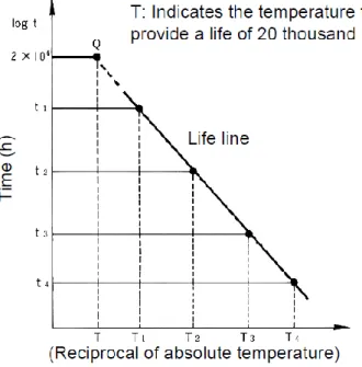
By conducting the accelerated aging tests for at least 3 or 4 temperatures (higher than the maximum allowed temperature) and plotting the corresponding lifespans on log(t)= 𝑓(1𝑇) graph, we can evaluate the thermal class by extrapolating the life line to lower temperatures and reading the cross-point with t = 20 000 [h] (see Figure 1.9). The thermal class is obtained by rounding down the temperature T (expressed in degree Celsius) to the closes value given by the standard [26] (see Table 1.2). The detailed test procedures, defining e.g. the choice of test temperatures or sample type, can be found in standards [27] [28].
Figure 1.9. The log(t)= 𝑓(1𝑇) plot used for calculating the thermal class T.
Table 1.2 presents thermal classes defined in [26] with examples of materials.
Table 1.2. Thermal classes with examples of materials [29] [12]
IEC 60085 Thermal class
IEC 60085 Previous nomenclature
Maximum hot spot temperature allowed Examples of materials 90 Y 90ºC Paper, polyethylene (PE) 105 A 105ºC Polychloropropylene 120 E 120ºC Polyethylene terephthalate (PET) 130 B 130ºC Melamine 155 F 155ºC Polyurethane (PU) 180 H 180ºC Polyester (PES) 200 200 200ºC Polyesterimide (PEI) /polyamidimide (PAI) 220 220 220ºC Polyamidimide (PAI)
Not present in IEC60085, but exists in NEMA standard MG-1 Motors and
Generators (class S)
240ºC Polyimide (PI)
250 250 250ºC Inorganic components
1.2.2.2.4. Breakdown strength
The breakdown strength, called also (di-)electric strength, is defined [24] as a quotient of the maximum voltage applied without breakdown U, by the distance d between conducting parts under prescribed test conditions:
𝐸𝑏 =
𝑈
𝑑 (1.14)
The breakdown strength depends on multiple conditions, such as [12] [19]:
Type of dielectric material, its purity and presence of imperfections,
Voltage waveform (DC, sine wave, square wave, surge, etc.),
Voltage frequency,
Rate of voltage amplitude increase (usually around 1kV/s),
Settings of maximum leakage current,
Electric field configuration (shape of electrodes, their size),
Experimental conditions (temperature, humidity, pressure etc.),
Sample thickness and surface (generally speaking the thicker the sample or the larger the sample surface the lower the breakdown strength due to higher probability of finding structure imperfections).
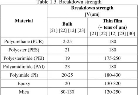
Table 1.3 presents some examples of breakdown strengths for insulating materials.
Table 1.3. Breakdown strength
Material Breakdown strength [V/μm] Bulk [21] [22] [12] [23] Thin film (~ tens of μm) [21] [22] [12] [23] [30] Polyurethane (PUR) 2-25 180 Polyester (PES) 21 180 Polyesterimide (PEI) 19 175-250 Polyamidimide (PAI) 23 180 Polyimide (PI) 20-25 180-430 Epoxy 20 130-320 Mica 80-130 120-250
1.3. Electrical insulation system of low voltage motors
The insulation system plays a very important role and its presence is absolutely substantial to assure the correct functioning of any electric machine. The properties of materials used in the insulation system are the key factor determining the machine rated voltage, life expectancy or thermal class.
The role of the insulation system is threefold [6] [31]:
Electrical short circuits preventions
This is a primary function of the insulation system. Any short circuits due to dysfunction of the insulation system leads, usually very soon, to a complete breakdown of the machine. The choice of the insulating materials and their thickness is dictated by the machines rated voltage. In low voltage machines, almost solely the type I insulating materials are used (see section 1.2.2.1.1), due to their low cost and easy manufacturing. The thickness of any insulating material must be adapted in such a way that its breakdown voltage is significantly higher than the applied voltage. The lifespan of the weakest part insulating system will define the life expectancy of the whole machine.
Dissipation of heat loses
According to Joule’s first law, the current I circulating inside the conductor having the electrical resistance R produces the energy proportional to I2R. Thus the
current circulation inside the winding creates the heat, which is often referred as copper losses (or more generally speaking winding losses). This heat needs to be dissipated in order not to increase too much the temperature of the winding. Unless, the high temperature will decrease the machine efficiency as well as greatly accelerate the insulation aging process. The heat must be transferred to the heat sink (stator frame) via some parts of the insulation system. As most of the insulating materials are very bad heat conductors, their thickness must be elaborately chosen not to worsen the heat transport yet still assuring their primary function.
Winding movement prevention
Winding is subjected to many forces that may displace its parts. Such movement might occur due to transport, mechanical vibrations as a result of machine working or Lorentz forces acting on conductors in the magnetic field of the machine. One of the functions of the impregnating varnish (see section 1.3.4) is to prevent any movement of
any parts of the winding and to glue the wires together. Additionally, in order to keep the winding inside the slots, wedges or top sticks are used.
The design of the insulation system is a complex process. Generally speaking, the thicker insulation is, the higher its breakdown voltage and the longer the lifespan. On the other hand, thicker insulation usually means worse heat dissipation and thus lower overall efficiency of the machine as well as smaller specific output (power-to-mass ratio) due to, inter alia, smaller slot fill factor.
The insulating components in low voltage machines can be divided according to their function into the following groups [6]:
Phase-to-ground insulation (see section 1.3.1)
Phase-to-phase insulation (see section 1.3.2)
Turn-to-turn insulation (see section 1.3.3)
Impregnating varnish or resin (see section 1.3.4)
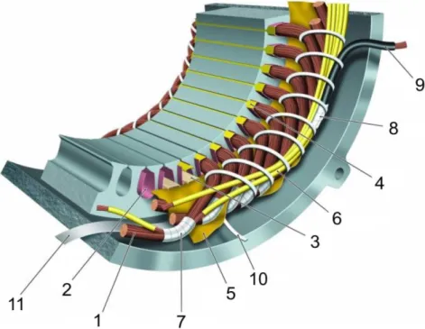
The first three components are often called primary or major insulation, as opposed to impregnating liquid, which is a secondary insulation. Figure 1.10 shows the overview of the components of a low-voltage insulation system.
Figure 1.10. Overview of materials in a low-voltage insulation system: 1 turn insulation, 2 slot liner, 3 slot separator, 4 wedge, 5 phase separator, 6 lead sleeving,
1.3.1. Phase-to-ground insulation
The phase-to-ground insulation prevents the winding coils from touching the stator core. Each slot of the stator is lined with a slot liner (see Figure 1.10 – 2). Slot liner is made most commonly of so-called insulating “paper”, although it is a synthetic material, such as aramid paper (well-known under its DuPont trade name NomexTM), polyester film (known as MylarTM) or polyester fleece (known as DacronTM). Generally, they present high breakdown strength, good mechanical properties, such as tear resistance and they resist well to chemical attack. The choice of the insulating material is often defined by the thermal class of the machine. The slot liners are available in wide range of thicknesses, depending of their voltage class [6] [31].
In order to further improve the properties of these discrete materials they can be piled together into flexible laminates. These laminates are best known under their trade names, e.g. NMN (NomexTM/MylarTM/NomexTM) or DMD (DacronTM/MylarTM/DacronTM).
1.3.2. Phase-to-phase insulation
The phase-to-phase insulation prevents the any two coils of different phases from touching one-another. At the end winding the coils are separated by the phase separators (see Figure 1.10 – 5). For those winding configurations with two different phases in the slots, their coil must be separated by the slop separators (see Figure 1.10 – 3).
For phase insulation, the same materials are used as for the phase-to-ground insulation (see section 1.3.1). The insulators are typically slightly thicker due to higher voltage that they need to support. For specific machines, usually type II, DacronTM tapes are used as enwinding phase separators, as they retain the varnish during impregnation thus improving their insulating properties. This effect is undesired for the slot separators because it would limit the slot fill factor [6] [31].
1.3.3. Turn-to-turn insulation
The role of turn-to-turn insulation is to electrically separate the turns of the same coil from each other. In low voltage machines this insulation consists in the thin enamel layer on the copper wire. For each diameter of a magnet wire there are 2 main enamel
thicknesses available: grade 1 (thinner enamel) and grade 2 (thicker enamel). Some producers offer also grade 3 with a thicker enamel layer. All the wire dimensions are standardized in European standard IEC 60317-0-1 [32] or American standard NEMA MW1000. Table 1.4 shows the wire dimensions for few diameters used in this thesis.
Table 1.4. Standard magnet wire dimensions and tolerances (some examples) [32]
Nominal conduction diameter [mm] Conductor diameter tolerance (±) [mm] Min. increase [mm] Max. overall diameter [mm]
Grade 1 Grade 2 Grade 1 Grade 2
0.500 0.005 0.024 0.045 0.544 0.566
0.800 0.008 0.030 0.056 0.855 0.884
1.000 0.010 0.034 0.063 1.062 1.094
1.120 0.011 0.034 0.065 1.184 1.217
The higher enamel grade allows higher breakdown strength and longer lifespan of the insulation [32]. On the other hand it limits the slot fill factor and thus lower power-to-mass ratio. Figure 1.11 shows the maximum slot fill factor as a function of insulation grading and nominal conductor diameter.
Figure 1.11. Maximum slot fill factor as a function of insulation grading and nominal conductor diameter according to IEC 60317-0-1 [32].
1.3.3.1. Magnet wire manufacturing process
Figure 1.12 presents the manufacturing process of enameled wire.
Figure 1.12. Winding Wire Production Flow. Description in the text below. [33]
First the bare wire of an appropriate diameter is annealed in the oven (1) in order to soften the copper. Then the very thin layer (about 1 μm thick) of the enamel is applied (2) on the copper surface to guarantee good adhesion and ensure good insulating properties. In the oven (3) the enamel is cured to evaporate the solvent from the enamel. The process of application and curing is repeated up to 30 times in order to achieve the desired enamel thickness. Once all the layers of enamel are cured, the lubricant is applied (4) to achieve a good slidability of the magnet wire. During the whole manufacturing process the outer diameter (5) and winding tension (6) are continuously controlled. Finally the product is reeled on a supply spool (7) [33] [30].
Due to the complicated manufacturing process, the properties of each layer of the enamel are slightly different. The one closest to the copper core undergoes multiple curing processes, while the external layer just one. As the standard [32] allows some dispersion the enamel thickness may vary, especially from one lot to another. It may change also along the wire of the same spool, especially due to centricity problems (copper core might not be centered). All these factors increase significantly the dispersion of any tests conducted on magnet wires.
1.3.3.2. Enamel materials
Magnet wires are covered with different enamels. They can be divided into 2 main categories: conventional wires (see section 1.3.3.2.1), covered with polymer enamel, and so-called corona resistant wires (see section 1.3.3.2.2) where the polymer matrix is charged with the nanoparticles of inorganic oxides.
1.3.3.2.1. Conventional wires
There are several polymer materials widely used as enamel in conventional magnet wires. They present different thermal properties, thus are classified in different thermal class. Table 1.5 presents the list of polymer enamels with their properties.
Table 1.5. Typically used conventional enamel materials for magnet wires [33] [30] [34]
Polymer name Abbr. Thermal
Class Properties
Polyurethane PUR 155 180
Good solderability
Not for high current nor for high temperature applications
Polyester PES 180 Not solderable Not suitable for high moisture applications Polyesterimide PEI 180
Solderable (at high temperatures) Good thermal properties
Good chemical resistance Polyesterimide
/polyamidimide PEI/PAI 200
PEI basecoat with PAI topcoat Not solderable
PAI topcoat guarantees better resistance to chemicals and moisture
Polyamidimide PAI 220
Not solderable
Very good thermal properties Good chemical resistance
Suitable for high moisture applications Low coefficient of friction
Polyimide PI 240
Not solderable
Very good properties even at very high temperatures (highest thermal index) Excellent chemical resistance High radiation resistance
1.3.3.2.2. Corona resistant wires
As mentioned before (see section 1.2.2.1) synthetic polymer materials are easily eroded by a partial discharges activity. The enamel of conventional wires is also highly vulnerable to PDs. On the other hand, inorganic materials can withstand a partial
discharges activity for a long time, but are hard to process and thus expensive (see section 1.2.2.1.2).
Magnet wire manufacturer desired to combine the advantages of those two groups of materials. As a result, composite materials were developed, where the micro- or nano- inorganic particles, such as TiO2, SiO2 or Al2O3, are dispersed in the polymer
matrix. The wires enameled with such composites are often referred to as “corona resistant”. Although they are not completely resistant to a PD activity, they have significantly higher breakdown strength and lifespan in a partial discharges regime than the conventional wires.
The properties of such composites depend naturally on 2 factors: the properties of the polymer matrix (will influence for example the thermal class) and of the inorganic filler. For the filler, the key factor defining the final properties of the magnet wire is the size of the particles, or rather of the possible aggregates in the final composite. The smaller the particles are, the bigger the surface contact is. This zone of contact, called interface, has recently gained increased attention in order to better understand its influence on the properties of the final product. Nevertheless, these composite materials, although having only few weight percent of inorganic particles, exhibits very interesting properties. They have higher breakdown strength but especially significantly longer lifespan than the conventional wires while exposed to partial discharges activity [35].
1.3.4. Impregnating varnish or resin
As mentioned before, the impregnation liquid serves in the machines as a secondary insulation. Naturally it strengthens the primary insulation, but also improves heat transfer (better thermal conductor than the air) as well as mechanically blocks the winding and protects it toward vibrations and environmental conditions.
The difference between the varnish and resin is in the solvent. In order to lower the viscosity of the resin to facilitate the application process an important quantity of organic solvents is added to achieve varnish. These solvents evaporate during curing and later on during drying, allowing the toughening of the coating. As during this process large quantities of potentially toxic volatile organic compounds (VOC) are emitted, the solventless resins are become more and more popular.
The polymers most commonly used as the impregnating varnishes or resins are [6] [31]:
Polyester-based liquids: easy to use, but brittle and dielectrically weak at high temperatures
Epoxy-based liquids: mechanically and chemically more resistant, but quite viscous; better proprieties in high temperatures that the polyester-based ones
Polyesterimide-based liquids: similar to polyester-based, but with better thermal properties
One has to remember that the solvent properties as well as many additives may change significantly the proprieties of the impregnating liquids. As the detailed data is often kept secret by the producers, it is difficult to compare products based only on their principle chemistries.
1.4. Partial discharges
According to the standard definition [24], a partial discharge (PD) (sometimes referred to as a partial breakdown (PB) [19]), is an electric discharge that only partially bridges the insulation between two conductors.
Papers [36] [37] define partial discharges (called corona) as a type of localized discharges resulting from transient gaseous ionization in an insulation system when the voltage stress exceeds a critical value. This ionization process is localized over only a portion of the distance between the electrodes of the system.
Partial discharges can be classified into 3 categories depending on their nature [19]:
Corona discharges: when stable partial discharges occurs at a free electrode in gaseous dielectrics;
Internal partial discharges: when discharges occur in gas voids imprisoned inside solid or liquid dielectrics;
Surface discharge (also commonly known as tracking discharges): when discharges occur on the surface of solids or liquid dielectrics but in gas.
This study is mainly concentrated on internal partial discharges. In the next sections of this chapter we will concentrate on breakdown in gases (mainly air).
Partial discharges give rise to multiples secondary effects, such as [36]:
Generation of ultraviolet radiation and light;
Nascent oxygen (strong oxidizing agent) that can produce ozone and in the presence of moisture, nitric acids (see chapter 3);
Absorption or generation of different substances, also gaseous, within enclosed voids;
Heat generation in the discharge channel and power losses in the power supply;
Mechanical erosion of surfaces by ion bombardment;
Interference with radio communication within the broadcast band frequency spectrum;
These phenomena are the basis of different techniques used to detect the partial discharges activity. Those methods are described in chapter 2.
1.4.1. Discharge mechanism
The breakdown of a gas is possible only by forming a highly conductive channel between the electrodes. It means the necessity of vigorous ionization processes in order to produce a large number of charge carriers. The phenomenon strongly depends on multiple conditions, such as parameters of electric field (its uniformity, electrodes shapes, gap distances), gas type and experimental conditions (pressure, temperature, humidity, etc.).
There are two basic mechanisms of breakdown in gases: Townsend mechanism [38] and Streamer mechanism [39] [40]. They will be discussed in the following sections.
1.4.1.1. Townsend mechanism
The multiplication of charge carries in gas takes place mainly by impact of electrons with neutral molecules, which is known as α or primary ionization. The secondary or β process, occurs when ions make a contribution to ionization by ejecting electrons from the electrodes surface after impact.
In order to begin a discharge process, some charge carries, called germs, need to be present in the gas before applying the electric field. When an electron accelerated by the electric field gains sufficient energy to ionize, i.e. ejecting another electron from the neutral molecule leaving behind a positive ion (α process), the new electron, along with the primary electron, continue the process of ionization. The process continues, releasing further electrons, thus creating an electron avalanche [19] [36].
By neglecting the processes of recombination and diffusion, the number of electrons dnx produced by collisions in element dx at distance x from the electrode can
be calculated as:
𝑑𝑛𝑥 = 𝑛𝑥𝛼𝑑𝑥 (1.15)
where:
α – Townsend’s first ionization coefficient [1
cm]
nx – number of electrons at distance x from electrode
By solving the equation (1.15) for a case of very small gap length d, the number of electrons striking the anode per second is:
𝑛𝑑= 𝑛0𝑒𝛼𝑑 (1.16)
Thus each from n0 germ electrons leaving the cathode produces (𝑒𝛼𝑑− 1) new electrons
and the same number of positive ions while traversing the distance d.
The Townsend’s first ionization coefficient α for electropositive gases is defined as the mean number of ionizing collision made by a single electron while its drift across the gap in a uniform field [19]. In air, this coefficient at a constant temperature can be approximated by [41]: 𝛼 ≈ 1.11 × 10⁻⁴(𝐸 𝑝− 25.1) 2 ∙ 𝑝 (1.17) where:
E – electric field strength [V
cm]
p – air pressure [Torr]
During an electrical breakdown, a conducting channel bridges the electrodes through the insulating gas. The electrons required to build this channel are not only produced within the gas across the gap (α process), but are also released from the electrode surface ( process). These ionization processes are a consequence of the transfer of energy gained by the electrons in an avalanche:
effect of positive ions (they have sufficient energy to eject the electrons upon striking the cathode);
photon effect (the cathode radiation from excited molecules returning to their ground state energy level);
metastable effect (molecules in this condition may diffuse back to the cathode thus causing electrons emission on striking) [19] [42].
The Townsend’s secondary ionization coefficient is defined as the number of secondary electrons on an average produced at the cathode per electron generated by the
α process [19]. It strongly depends upon the cathode material, field intensity and gas
pressure. As a result the mean number of secondary electrons μ is:
𝜇 = 𝛾(𝑒𝛼𝑑− 1) (1.18)
In order for the process to be self-sustaining, the μ must meet so-called Townsend criterion:
Figure 1.13 presents the schematic of Townsend breakdown mechanism.
Figure 1.13. Schematic of Townsend breakdown mechanism [19]
1.4.1.2. Streamer mechanism
The avalanche exponential growth, being the base of Townsend’s mechanism, requires uniform field. However, this hypothesis is no longer valid if the electrical field modification due to space charges (electrons and ions) cannot be neglected. Once the number of charge carriers in an avalanche exceeds ~107 to 108, the head of the avalanche (consisting mostly of electrons) and its tail (mostly ions) are in a state of an enhanced field. Thus the ionization has a higher rate at the avalanche extremities (head and tail) than at the center. The avalanche can proceeds faster toward the anode by
![Table 1.1. Standard values of electrical properties of some solid insulating materials (at 20ºC) [21] [22] [12] [23] [18] Insulating material](https://thumb-eu.123doks.com/thumbv2/123doknet/2133464.8652/31.892.132.809.769.1057/electrical-properties-insulating-insulating-polyurethane-poliamideimide-polyimide.webp)
![Figure 1.11. Maximum slot fill factor as a function of insulation grading and nominal conductor diameter according to IEC 60317-0-1 [32]](https://thumb-eu.123doks.com/thumbv2/123doknet/2133464.8652/39.892.271.669.743.1045/figure-maximum-function-insulation-grading-conductor-diameter-according.webp)
![Figure 1.22. Overvoltage at the motor terminals as a function of cable length for different risetimes [58]](https://thumb-eu.123doks.com/thumbv2/123doknet/2133464.8652/60.892.164.695.110.484/figure-overvoltage-motor-terminals-function-length-different-risetimes.webp)
![Figure 1.23. Transient voltage waveforms at the different parts of the coils (left) and the resulting turn-to-turn voltage calculated between these parts [60]](https://thumb-eu.123doks.com/thumbv2/123doknet/2133464.8652/61.892.159.782.99.355/figure-transient-voltage-waveforms-different-resulting-voltage-calculated.webp)